WIKA IPT-2 Series Operating Instructions Manual
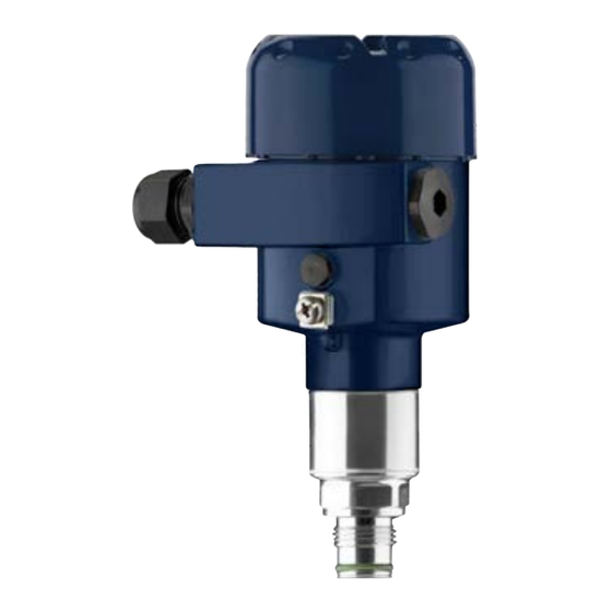
Process pressure transmitter
Hide thumbs
Also See for IPT-2 Series:
- Safety manual (20 pages) ,
- Operating instructions manual (76 pages)

Related Manuals for WIKA IPT-2 Series


Summary of Contents for WIKA IPT-2 Series
- Page 1 Operating Instructions Process pressure transmitter IPT-2x 4 … 20 mA Metallic sensor Process pressure transmitter IPT-2x...
-
Page 2: Table Of Contents
Diagnostics and servicing ....................43 Maintenance ........................43 Diagnosis function ......................43 Rectify faults ........................45 Exchange process module on version IP 68 (25 bar) ............. 46 Instrument repair ......................47 Dismount..........................48 Dismounting steps......................48 WIKA Operating Instructions - Process pressure transmitter IPT-2x... - Page 3 Dimensions ........................67 Trademark ........................75 Safety instructions for Ex areas Take note of the Ex specific safety instructions for Ex applications. These instructions are attached as documents to each instrument with Ex approval and are part of the operating instructions. Editing status: 2019-03-11 WIKA Operating Instructions - Process pressure transmitter IPT-2x...
-
Page 4: About This Document
This arrow indicates a single action. Sequence of actions Numbers set in front indicate successive steps in a procedure. Battery disposal This symbol indicates special information about the disposal of bat- teries and accumulators. WIKA Operating Instructions - Process pressure transmitter IPT-2x... -
Page 5: For Your Safety
Arbi- trary conversions or modifications are explicitly forbidden. For safety reasons, only the accessory specified by the manufacturer must be used. To avoid any danger, the safety approval markings and safety tips on the device must also be observed and their meaning read in this oper- ating instructions manual. WIKA Operating Instructions - Process pressure transmitter IPT-2x... -
Page 6: Eu Conformity
This information is only valid for USA and Canada. Hence the follow- ing text is only available in the English language. Installations in the US shall comply with the relevant requirements of the National Electrical Code (ANSI/NFPA 70). Not fulfilled when connecting to an external display and adjustment unit. WIKA Operating Instructions - Process pressure transmitter IPT-2x... - Page 7 Installations in Canada shall comply with the relevant requirements of the Canadian Electrical Code A Class 2 power supply unit has to be used for the installation in the USA and Canada. WIKA Operating Instructions - Process pressure transmitter IPT-2x...
-
Page 8: Product Description
Hardware from 1.0.0 • Software from 1.3.4 Note: You can find the hardware and software version of the instrument as follows: • On the type plate of the electronics module • In the adjustment menu under "Info" Type label The type label contains the most important data for identification and use of the instrument: WIKA Operating Instructions - Process pressure transmitter IPT-2x... -
Page 9: Principle Of Operation
Measured products are gases, vapours and liquids. IPT-2x is especially suitable for applications with higher temperatures and high pressures. Measured variables The IPT-2x is suitable for the measurement of the following process variables: • Process pressure • Level WIKA Operating Instructions - Process pressure transmitter IPT-2x... - Page 10 Fig. 3: Configuration of the measuring system with piezoresistive sensor ele- ment Sensor element Base element Transmission liquid Process diaphragm Strain gauge (DMS) sensor element For measuring ranges above 100 bar, a strain gauge (DMS) sensor element (dry system) is used. WIKA Operating Instructions - Process pressure transmitter IPT-2x...
- Page 11 Absolute pressure: the measuring cell is evacuated and encapsu- lated. The ambient pressure is not compensated and does hence influence the measured value. Seal concept The measuring system is completely welded and thus sealed against the process. WIKA Operating Instructions - Process pressure transmitter IPT-2x...
-
Page 12: Supplementary Cleaning Procedures
Not exposed to corrosive media • Protected against solar radiation • Avoiding mechanical shock and vibration • Storage and transport Storage and transport temperature see chapter "Supplement - temperature Technical data - Ambient conditions" WIKA Operating Instructions - Process pressure transmitter IPT-2x... - Page 13 3 Product description • Relative humidity 20 … 85 % Lifting and carrying With instrument weights of more than 18 kg (39.68 lbs) suitable and approved equipment must be used for lifting and carrying. WIKA Operating Instructions - Process pressure transmitter IPT-2x...
-
Page 14: Mounting
Tightening can cause damage, e. g. to the rotation mechanism of the housing. If there is strong vibration at the mounting location, the instrument Vibrations version with external housing should be used. See chapter "External housing". WIKA Operating Instructions - Process pressure transmitter IPT-2x... -
Page 15: Ventilation And Pressure Compensation
When quickly opening/closing the housing cover, the measured value can change for approx. 5 s by up to 15 mbar. For an effective ventilation, the filter element must be always free from buildup. In case of horizontal mounting, turn the housing so that the filter element points downward after the instrument is installed. This provides better protection against buildup. Caution: Do not use a high-pressure cleaner. The filter element could be dam- aged, which would allow moisture into the housing. The following paragraphs describe how the filter element is arranged in the different instrument versions. WIKA Operating Instructions - Process pressure transmitter IPT-2x... - Page 16 This provides better protection against buildup. Fig. 8: Position of the filter element - Ex-d version Rotatable metal ring Filter element Instruments with absolute pressure have a blind plug mounted instead of the filter element. WIKA Operating Instructions - Process pressure transmitter IPT-2x...
-
Page 17: Process Pressure Measurement
Instruments with absolute pressure have a blind plug mounted instead of the filter element. Process pressure measurement Measurement setup in Keep the following in mind when setting up the measuring system: gases • Mount the instrument above the measuring point Possible condensation can then drain off into the process line. WIKA Operating Instructions - Process pressure transmitter IPT-2x... - Page 18 Siphon in U or circular form Pipeline A protective accumulation of water is formed through condensation in the pipe bends. Even in applications with hot steam, a medium temperature < 100 °C on the transmitter is ensured. WIKA Operating Instructions - Process pressure transmitter IPT-2x...
-
Page 19: Level Measurement
Mount the instrument below the min. level • Do not mount the instrument close to the filling stream or emptying area • Mount the instrument so that it is protected against pressure shocks from the stirrer Fig. 14: Measurement setup for level measurement WIKA Operating Instructions - Process pressure transmitter IPT-2x... -
Page 20: External Housing
4 Mounting External housing Configuration Fig. 15: Configuration, process module, external housing Pipeline Process module Connection cable process assembly - External housing External housing Signal cable WIKA Operating Instructions - Process pressure transmitter IPT-2x... -
Page 21: Connecting To Power Supply
In electroplating plants as well as plants for cathodic corrosion protec- tion it must be taken into account that significant potential differences exist. This can lead to unacceptably high currents in the cable screen if it is grounded at both ends. WIKA Operating Instructions - Process pressure transmitter IPT-2x... -
Page 22: Connecting
4. Remove approx. 10 cm (4 in) of the cable mantle, strip approx. 1 cm (0.4 in) of insulation from the ends of the individual wires 5. Insert the cable into the sensor through the cable entry WIKA Operating Instructions - Process pressure transmitter IPT-2x... -
Page 23: Single Chamber Housing
10. Reinsert the display and adjustment module, if one was installed 11. Screw the housing lid back on The electrical connection is finished. Single chamber housing The following illustration applies to the non-Ex as well as to the Ex-ia version. WIKA Operating Instructions - Process pressure transmitter IPT-2x... -
Page 24: Housing Ip 66/Ip 68 (1 Bar)
Housing IP 66/IP 68 (1 bar) Wire assignment, con- nection cable Fig. 18: Wire assignment in permanently connected connection cable Brown (+) and blue (-) to power supply or to the processing system Shielding WIKA Operating Instructions - Process pressure transmitter IPT-2x... -
Page 25: External Housing With Version Ip 68 (25 Bar)
External housing Electronics and connec- tion compartment for power supply 4...20mA 6 7 8 Fig. 20: Electronics and connection compartment Electronics module Cable gland for voltage supply Cable gland for connection cable, transmitter WIKA Operating Instructions - Process pressure transmitter IPT-2x... -
Page 26: Switch-On Phase
5 s: • Internal check of the electronics • Indication of a status message on the display or PC • Output signal at instruments with current output jumps to the set fault current WIKA Operating Instructions - Process pressure transmitter IPT-2x... - Page 27 5 Connecting to power supply Then the actual measured value is output to the signal cable. The value takes into account settings that have already been carried out, e.g. default setting. WIKA Operating Instructions - Process pressure transmitter IPT-2x...
-
Page 28: Set Up With The Display And Adjustment Module
5 s, the display returns to the main menu. The menu language is then switched over to "English". Approx. 60 minutes after the last pressing of a key, an automatic reset to measured value indication is triggered. Any values not confirmed with [OK] will not be saved. WIKA Operating Instructions - Process pressure transmitter IPT-2x... -
Page 29: Measured Value Indication
The return to the measured value indication is carried out through the [->] or [ESC] keys or automatically after 3 s Note: You can find a description of the individual steps in the quick setup guide of the sensor. You can find "Extended adjustment" in the next sub-chapter. WIKA Operating Instructions - Process pressure transmitter IPT-2x... -
Page 30: Parameter Adjustment - Extended Adjustment
Letters from A … Z • Numbers from 0 … 9 • Special characters +, -, /, - Setup - Application In this menu item you activate/deactivate the slave sensor for elec- tronic differential pressure and select the application. WIKA Operating Instructions - Process pressure transmitter IPT-2x... - Page 31 [OK] and jump to the next menu item with the [ESC] and the [->] key. Setup - Position correc- Especially with chemical seal systems, the installation position of the tion instrument can shift (offset) the measured value. Position correction compensates this offset. In the process, the actual measured value is taken over automatically. With relative pressure measuring cells a manual offset can also be carried out. WIKA Operating Instructions - Process pressure transmitter IPT-2x...
- Page 32 The actual product level during this adjustment is not important, because the min./max. adjustment is always carried out without changing the product level. These settings can be made ahead of time without the instrument having to be installed. WIKA Operating Instructions - Process pressure transmitter IPT-2x...
- Page 33 [OK]. Setup - Span adjustment Proceed as follows: 1. Select with [->] the menu item Span adjustment and confirm with [OK]. 2. Edit the mbar value with [OK] and set the cursor to the requested position with [->]. WIKA Operating Instructions - Process pressure transmitter IPT-2x...
- Page 34 4. Enter the pressure value for the full vessel (e.g. 900 mbar) cor- responding to the percentage value. 5. Save settings with [OK] The max. adjustment is finished. For an adjustment with filling, simply enter the actual measured value indicated at the bottom of the display. WIKA Operating Instructions - Process pressure transmitter IPT-2x...
- Page 35 In the menu item "Current output Min./Max.", you determine the reac- (Min./Max.) tion of the current output during operation. The device assumes an approximately constant temperature and static pressure and converts the differential pressure into the flow rate via the characteristic curve extracted by root. WIKA Operating Instructions - Process pressure transmitter IPT-2x...
- Page 36 Italian • Dutch • Portuguese • Japanese • Chinese • Polish • Czech • Turkish In delivery status, the IPT-2x is set to English. Display - Displayed value In this menu item, you define which measured value is displayed. 1 and 2 WIKA Operating Instructions - Process pressure transmitter IPT-2x...
- Page 37 In menu item "Peak value, temperature", both values are displayed. In another window you can carry out a reset of the two peak values separately. WIKA Operating Instructions - Process pressure transmitter IPT-2x...
- Page 38 Any user programmable linearization curve as well as the measured value memory are deleted. The following table shows the default values of the instrument. De- pending on the instrument version or application, all menu items may not be available or some may be differently assigned: WIKA Operating Instructions - Process pressure transmitter IPT-2x...
- Page 39 Display format 1 and 2 Backlight Switched on Reset - Diagnosis Menu item Parameter Default value Sensor status Peak value Pressure Actual measured value Temperature Actual temperature values from measuring cell, elec- tronics Simulation Process pressure WIKA Operating Instructions - Process pressure transmitter IPT-2x...
- Page 40 The data are saved only after release. Additional settings - Scal- In menu item "Scaling" you define the scaling variable and the scaling ing (1) unit for the level value on the display, e.g. volume in l. WIKA Operating Instructions - Process pressure transmitter IPT-2x...
- Page 41 Change the settings of the special parameters only after having con- tacted our service staff. In this menu item, you can read out the instrument name and the Info - Instrument name instrument serial number: WIKA Operating Instructions - Process pressure transmitter IPT-2x...
-
Page 42: Saving The Parameterisation Data
In the display and adjust- If the instrument is equipped with a display and adjustment module, ment module the parameter adjustment data can be saved therein. The procedure is described in menu item "Copy device settings". WIKA Operating Instructions - Process pressure transmitter IPT-2x... -
Page 43: Diagnostics And Servicing
• • F105 The instrument is still in the start phase, Wait for the end of the switch-on phase the measured value could not yet be Measured value is deter- determined mined WIKA Operating Instructions - Process pressure transmitter IPT-2x... - Page 44 Impermissible pressure • If necessary, use an instrument with a value higher measuring range Tab. 7: Error codes and text messages, information on causes as well as corrective measures WIKA Operating Instructions - Process pressure transmitter IPT-2x...
-
Page 45: Rectify Faults
Reaction after fault recti- Depending on the reason for the fault and the measures taken, the fication steps described in chapter "Setup" must be carried out again or must be checked for plausibility and completeness. WIKA Operating Instructions - Process pressure transmitter IPT-2x... -
Page 46: Exchange Process Module On Version Ip 68 (25 Bar)
4. Mount the new process module on the measuring point 5. Plug the connector back in 6. Mount the cable assembly on the process module and turn it to the desired position 7. Tighten the fixing screw with the hexagon key wrench The exchange is finished. WIKA Operating Instructions - Process pressure transmitter IPT-2x... -
Page 47: Instrument Repair
Complete one form for each instrument • If necessary, state a contamination • Clean the instrument and pack it damage-proof • Attach the completed form and possibly also a safety data sheet to the instrument WIKA Operating Instructions - Process pressure transmitter IPT-2x... -
Page 48: Dismount
Pass the instrument directly on to a specialised recycling company and do not use the municipal collecting points. If you have no way to dispose of the old instrument properly, please contact us concerning return and disposal. WIKA Operating Instructions - Process pressure transmitter IPT-2x... -
Page 49: Supplement
Transmission liquid with measuring ranges up to 40 bar. With measuring ranges from 100 bar dry measuring cell. Halocarbon oil: Generally in oxygen applications, not with vacuum measuring ranges, not with absolute meas- uring ranges < 1 bar WIKA Operating Instructions - Process pressure transmitter IPT-2x... - Page 50 Input variable - Piezoresistive/Strain gauge measuring cell The specifications are only an overview and refer to the measuring cell. Limitations due to the material and version of the process fitting as well as the selected pressure type are possible. The specifications on the nameplate apply. Glass with Aluminium and stainless steel precision casting housing Only for 316L with 3A approval Between transmitter and external electronics housing. Fix connected to the sensor. WIKA Operating Instructions - Process pressure transmitter IPT-2x...
- Page 51 0 … +30 psig +90 psig -14.5 psig 0 … +150 psig +450 psig -14.5 psig 0 … +300 psig +900 psig -14.5 psig 0 … +500 psig +1500 psig -14.5 psig WIKA Operating Instructions - Process pressure transmitter IPT-2x...
- Page 52 +50 bar/+5000 kPa -1 bar/-100 kPa -1 … +25 bar/-100 … +2500 kPa +50 bar/+5000 kPa -1 bar/-100 kPa -0.2 … +0.2 bar/-20 … +20 kPa +20 bar/+3000 kPa -1 bar/-100 kPa WIKA Operating Instructions - Process pressure transmitter IPT-2x...
- Page 53 0 … 300 psi 725 psig 0 psi Adjustment ranges Specifications refer to the nominal measuring range, pressure values lower than -1 bar cannot be Min./Max. adjustment: Ʋ Percentage value -10 … 110 % Ʋ Pressure value -20 … 120 % Zero/Span adjustment: Ʋ Zero -20 … +95 % WIKA Operating Instructions - Process pressure transmitter IPT-2x...
- Page 54 : dead time; t : rise time; t : jump response time Process variable Output signal IPT-2x IPT-2x - IP 68 (25 bar) Dead time ≤ 25 ms ≤ 50 ms The indication values can be assigned individually. WIKA Operating Instructions - Process pressure transmitter IPT-2x...
- Page 55 4 … 20 mA and refers to the set span. Turn down (TD) is the ratio "nominal measuring range/set span". The thermal change of the zero signal and output span corresponds to the value F in chapter "Calculation of the total deviation (according to DIN 16086)". Piezoresistive/strain gauge measuring cell Different availability depending on measuring range and process fitting WIKA Operating Instructions - Process pressure transmitter IPT-2x...
- Page 56 In the table, example values for typical Turn downs are listed. Turn Down TD 1 : 1 TD 2.5 : 1 TD 5 : 1 TD 10 : 1 TD 20 : 1 Factor FTD 1.75 10.5 Ceramic/metal measuring cell WIKA Operating Instructions - Process pressure transmitter IPT-2x...
- Page 57 Applies also to the analogue 4 … 20 mA current output and refers to the set span. Thermal change, current output < 0.05 %/10 K, max. < 0.15 %, each with -40 … +80 °C (-40 … +176 °F) WIKA Operating Instructions - Process pressure transmitter IPT-2x...
- Page 58 -20 … +60 °C (-4 … +140 °F) ble PE Process conditions - Piezoresistive/Strain gauge measuring cell Process temperature With ceramic/metallic measuring cell with gold-coated diaphragm, the values must be multiplied with factor 3. WIKA Operating Instructions - Process pressure transmitter IPT-2x...
- Page 59 40 °C (104 °F) 0 °C (32 °F) 85 °C 150 °C (185 °F) (302 °F) Fig. 31: Temperature derating IPT-2x, version up to +150 °C (+302 °F) Process temperature Ambient temperature Process fittings acc. to DIN 3852-A, EN 837 WIKA Operating Instructions - Process pressure transmitter IPT-2x...
- Page 60 60 °C (140 °F) 0 °C (32 °F) 110 °C 150 °C (230 °F) (302 °F) Fig. 32: Temperature derating IPT-2x, version up to +150 °C (+302 °F) Process temperature Ambient temperature Instrument configuration suitable for vapour WIKA Operating Instructions - Process pressure transmitter IPT-2x...
- Page 61 M20 x 1.5; ½ NPT Ʋ Closing cap ½ NPT Depending on the instrument version. 2 g with housing version stainless steel double chamber IP 66/IP 68 (0.2 bar), only with absolute pressure. WIKA Operating Instructions - Process pressure transmitter IPT-2x...
- Page 62 Ʋ Wire cross-section 0.5 mm² (AWG 20) Ʋ Wire resistance 0.037 Ω/m (0.012 Ω/ft) Display and adjustment module Display element Display with backlight Measured value indication Ʋ Number of digits Breather capillaries not with Ex-d version. WIKA Operating Instructions - Process pressure transmitter IPT-2x...
- Page 63 (24 V - 9.6 V)/0.022 A = 655 Ω = 24 V DC Potential connections and electrical separating measures in the instrument Electronics Not non-floating Reference voltage 500 V AC Conductive connection Between ground terminal and metallic process fitting Galvanic separation between electronics and metal housing parts WIKA Operating Instructions - Process pressure transmitter IPT-2x...
-
Page 64: Calculation Of The Total Deviation
: Total deviation total • : Basic deviation • perf : Long-term stability stab • : Thermal change of zero signal and output span (temperature error) • : Deviation Protection rating IP 66/IP 68 (0.2 bar) only in conjunction with absolute pressure. When used with fulfilled housing protection. WIKA Operating Instructions - Process pressure transmitter IPT-2x... -
Page 65: Calculation Of The Total Deviation - Practical Example
TD 20 : 1 Factor FTD 1.75 10.5 Tab. 29: Determination of the additional factor "turn down" for the above example: F = 1.75 TBasis = 0.15 % x 1 x 1.75 = 0.26 % WIKA Operating Instructions - Process pressure transmitter IPT-2x... - Page 66 The total deviation of the measurement is hence 0.57 %. Deviation in bar: 0.57 % of 4 bar = 22.8 mbar The example shows that the measurement error in practice can be considerably higher than the basic deviation. Reasons are temperature influence and Turn down. WIKA Operating Instructions - Process pressure transmitter IPT-2x...
-
Page 67: Dimensions
Fig. 36: Housing versions in protection IP 66/IP 67 and IP 66/IP 68 (0.2 bar) Plastic single chamber (IP 66/IP 67) Aluminium - single chamber Stainless steel single chamber (electropolished) Stainless steel single chamber (precision casting) Stainless steel single chamber (electropolished) IP 69K WIKA Operating Instructions - Process pressure transmitter IPT-2x... - Page 68 8 mm (0.12") (0.32") 110 mm x 90 mm (4.33" x 3.54") Fig. 37: IP 68 version with external housing Lateral cable outlet Axial cable outlet Plastic housing Stainless steel housing, electropolished WIKA Operating Instructions - Process pressure transmitter IPT-2x...
- Page 69 G½ A inside G¼ (ISO 228-1) ½ NPT, inside ¼ NPT (ASME B1.20.1) ½ NPT PN 1000 For the version with "Second Line of Defense", the measure of length increases by 17 mm (0.67 in). WIKA Operating Instructions - Process pressure transmitter IPT-2x...
- Page 70 3 and 4 with temperature adapter and screen sheet for 180 °C/200 °C 1½ NPT (ASME B1.20.1) For the version with "Second Line of Defense", the measure of length increases by 17 mm (0.67 in). WIKA Operating Instructions - Process pressure transmitter IPT-2x...
- Page 71 Collar socket DN 40 PN 40, DIN 11851 Collar socket DN 50 PN 25 Form A, DIN 11864 DRD PN 40 For the version with "Second Line of Defense", the measure of length increases by 17 mm (0.67 in). WIKA Operating Instructions - Process pressure transmitter IPT-2x...
- Page 72 Collar socket DN 40 PN 40, DIN 11851 Collar socket DN 50 PN 25 Form A, DIN 11864 DRD PN 40 For the version with "Second Line of Defense", the measure of length increases by 17 mm (0.67 in). WIKA Operating Instructions - Process pressure transmitter IPT-2x...
- Page 73 Flange connection according to DIN 2501 Flange connection according to ASME B16.5 Order-specific Order-specific For the version with "Second Line of Defense", the measure of length increases by 17 mm (0.67 in). WIKA Operating Instructions - Process pressure transmitter IPT-2x...
- Page 74 Temperature adapter up to 180 °C Temperature screen sheet up to 200 °C Order-specific Order-specific For the version with "Second Line of Defense", the measure of length increases by 17 mm (0.67 in). WIKA Operating Instructions - Process pressure transmitter IPT-2x...
-
Page 75: Trademark
9 Supplement Trademark All the brands as well as trade and company names used are property of their lawful proprietor/ originator. WIKA Operating Instructions - Process pressure transmitter IPT-2x... - Page 76 Linearisation 35 Maintenance 43 Measurement setup 17, 18, 19 Parameterization example 32 Peak value indicator 37 Position correction 31 Pressure compensation 17 – Ex d 16 – Standard 16 Process pressure measurement 18 Reset 38 WIKA Operating Instructions - Process pressure transmitter IPT-2x...
- Page 77 Notes WIKA Operating Instructions - Process pressure transmitter IPT-2x...
- Page 78 Notes WIKA Operating Instructions - Process pressure transmitter IPT-2x...
- Page 79 Notes WIKA Operating Instructions - Process pressure transmitter IPT-2x...
- Page 80 All statements concerning scope of delivery, application, practi- cal use and operating conditions of the sensors and processing systems correspond to the information available at the time of printing. WIKA Alexander Wiegand SE & Co. KG Alexander-Wiegand-Straße 30 63911 Klingenberg Germany...
Need help?
Do you have a question about the IPT-2 Series and is the answer not in the manual?
Questions and answers