
Related Manuals for WIKA IPT-1 series


Summary of Contents for WIKA IPT-1 series
-
Page 1: Operating Instructions
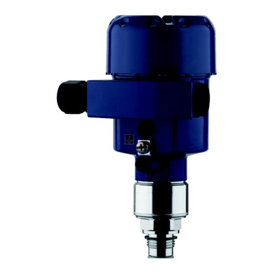
Operating Instructions Process pressure transmitter IPT-1* Vers. 3.0 - metalic sensor Profibus PA... -
Page 2: Table Of Contents
Contents Contents About this document Function........Target group ......Symbolism used. - Page 3 Contents Instrument repair ......38 Dismounting Dismounting steps ......39 Disposal .
-
Page 4: About This Document
1 About this document 1 About this document 1.1 Function This operating instructions manual provides all the information you need for mounting, connection and setup as well as important instructions for maintenance and fault rectification. Please read this information before putting the instrument into operation and keep this manual accessible in the immediate vicinity of the device. -
Page 5: For Your Safety
2 For your safety 2 For your safety 2.1 Authorised personnel Mount and set up the pressure transmitter only if you know the applicable national regulations and have the appropriate qualification. You must be aquainted with the regulations and instructions for hazardous areas, measurement and control technology as well as electrical circuits because the pressure transmitter is "electrical equipment"... -
Page 6: Safety Approval Markings And Safety Tips
With respect to compatibility, the NAMUR recommendation NE 53 is fulfilled. This applies also to the corresponding indicating and adjustment components. WIKA instruments are generally upward and downward compatible. Sensor software for DTM IPT-1* Vers. 3.0 HART, PA or FF DTM IPT-1* Vers. -
Page 7: Product Description
3 Product description 3 Product description 3.1 Configuration Scope of delivery The scope of delivery encompasses: IPT-1* Vers. 3.0 process pressure transmitter Documentation this operating instructions manual Operating instructions manual "Indicating and adjustment module" (optional) Supplementary instructions manual "Plug connector for con- tinuously measuring sensors"... -
Page 8: Principle Of Operation
(also available as a download).A CD with the appropriate files can be ordered via e-mail under info@de.WIKA.com or by phone from one of the WIKA agencies. The backlight of the indicating and adjustment module is powered by the sensor. -
Page 9: Packaging, Transport And Storage
3 Product description 3.4 Packaging, transport and storage Packaging Your instrument was protected by packaging during transport. Its capacity to handle normal loads during transport is assured by a test according to DIN EN 24180. The packaging of standard instruments consists of environment- friendly, recyclable cardboard. -
Page 10: Mounting
4 Mounting 4 Mounting 4.1 General instructions Suitability for process Make sure that all parts of the instrument in contact with the measured conditions product, especially the sensor element, process seal and process fitting, are suitable for the existing process conditions such as process pressure, process temperature as well as the chemical properties of the medium. - Page 11 4 Mounting Ventilation and pressure The ventilation of the measuring cell is realised by a filter element in compensation the socket of the electronics housing. The ventilation of the electronics housing is realised via an additional filter element around the cable glands.
-
Page 12: Mounting Instructions
4.3 Mounting steps To mount IPT-1* Vers. 3.0, a welded socket is necessary. Use Welding the socket components from the line of WIKA mounting accessories. à Note the applicable welding standards (segment welding proce- dure) when welding the socket. Sealing/Screwing in Use the seal corresponding to the instrument: Process fitting GD: Tesnit seal in front of the thread... -
Page 13: Connecting To Power Supply
5 Connecting to power supply 5 Connecting to power supply 5.1 Preparing the connection Note safety instructions Always keep in mind the following safety instructions: Connect only in the complete absence of line voltage If overvoltage surges are expected, overvoltage arresters should be installed according to Profibus specifications Take note of In hazardous areas you should take note of the appropriate... -
Page 14: Connection Procedure
5 Connecting to power supply Select connec- Take note of the corresponding installation regulations for Ex tion cable for Ex applications. In particular, make sure that no potential equalisation applications currents flow over the cable screen. In case of grounding on both sides this can be achieved by the use of a capacitor or a separate potential equalisation. -
Page 15: Wiring Plan, Single Chamber Housing
5 Connecting to power supply Check the hold of the wires in the terminals by lightly pulling on them 10 Connect the screen to the internal ground terminal, connect the outer ground terminal with potential equalisation 11 Tighten the compression nut of the cable entry. The seal ring must completely encircle the cable 12 Screw the housing cover on The electrical connection is finished. -
Page 16: Wiring Plan, Double Chamber Housing
5 Connecting to power supply Electronics and connec- tion compartment Display I ² C 5 6 7 8 Fig. 7: Electronics and connection compartment, single chamber housing Plug connector for service Spring-loaded terminals for connection of the external indicating and adjustment module Ground terminal for connection of the cable screen Spring-loaded terminals for voltage supply... - Page 17 5 Connecting to power supply Housing overview Fig. 9: Double chamber housing Housing cover, connection compartment Blind stopper or plug M12 x 1 for the external indicating and adjustment module (optional) Housing cover, electronics compartment Filter element for air pressure compensation Cable entry or plug Electronics compart- ment...
-
Page 18: Switch On Phase
5 Connecting to power supply Connection compart- ment I ² C Fig. 11: Connection compartment, double chamber housing Plug connector for service Ground terminal for connection of the cable screen Spring-loaded terminals for voltage supply Wiring plan I 2 C Fig. - Page 19 5 Connecting to power supply Then the current measured value will be displayed and the corre- sponding digital output signal will be outputted to the cable. The values correspond to the actual measured level as well as to the set- tings already carried out, e.g.
-
Page 20: Set Up With The Indicating And Adjustment Module
6 Set up with the indicating and adjustment module 6 Set up with the indicating and adjustment module 6.1 Short description Function/Configuration The indicating and adjustment module is used for measured value display, adjustment and diagnosis. It can be mounted in the following housing versions and instruments: All sensors of the IPT-1* instrument family, in the single as well as double chamber housing (optionally in the electronics or connec-... - Page 21 6 Set up with the indicating and adjustment module Fig. 13: Mounting the indicating and adjustment module Note: If you intend to retrofit the instrument with an indicating and adjustment module for continuous measured value indication, a higher cover with an inspection glass is required.
-
Page 22: Adjustment System
6 Set up with the indicating and adjustment module 6.3 Adjustment system Fig. 14: Indicating and adjustment elements LC display Indication of the menu item number Adjustment keys Key functions [OK] key: Move to the menu overview Confirm selected menu Edit parameter Save value [->] key to select:... -
Page 23: Setup Procedure
6 Set up with the indicating and adjustment module 6.4 Setup procedure Address setting Before starting the actual parameter adjustment of a Profibus PA sensor, the address setting must first be carried out. You will find a detailed description in the operating instructions manual of the indicating and adjustment module or in the online help of PACTware or DTM. - Page 24 6 Set up with the indicating and adjustment module Push the [OK] button in the measured value display, the menu overview is displayed. ▶ Basic adjustment Display Diagnostics Service Info Confirm the menu "Basic adjustment" with [OK], the menu item "Unit"...
- Page 25 6 Set up with the indicating and adjustment module Enter the requested density value with [->] and [+], confirm with [OK] and move to position correction with [->]. The adjustment unit is hence switched over from bar to m. Proceed as follows to select the temperature unit: à...
- Page 26 6 Set up with the indicating and adjustment module Information: For an adjustment with filling, you simply enter the displayed actual measured value. If the adjustment ranges are exceeded, the message "Outside parameter limits" appears. The editing procedure can be aborted with [ESC] or the displayed limit value can be accepted with [OK].
- Page 27 6 Set up with the indicating and adjustment module In the menu items "zero" and "span" you determine the span of the sensor, the span corresponds to the end value. Information: The steps 1, 3 and 4 are not necessary for instruments which are already preset according to customer specifications! You can find the data on the type label on the instrument or in the menu items of the zero/span adjustment.
- Page 28 6 Set up with the indicating and adjustment module ▶ Basic adjustment Display Diagnostics Service Info Confirm the menu "Basic adjustment" with [OK], the menu item "Unit" will be displayed. Unit Unit of measurement ▼ Temperature unit ▼ °C Activate the selection with [OK] and select "Units of measure- ment with [->].
- Page 29 6 Set up with the indicating and adjustment module Carrying out zero ad- Proceed as follows: justment Edit the mbar value in the menu item "zero" with [OK]. Zero adjustment 000.0 % +0000.0 mbar 0000.0 mbar Set the requested mbar value with [+] and [->]. Confirm with [+] and move to span adjustment with [->].
- Page 30 6 Set up with the indicating and adjustment module Copy sensor data This function enables reading out parameter adjustment data as well as writing parameter adjustment data into the sensor via the indicating and adjustment module. A description of the function is available in the operating instructions manual "Indicating and adjustment module".
- Page 31 6 Set up with the indicating and adjustment module Menu section Function Reset value 8888.8 Decimal point indication The values of the following menu items are not reset with "Reset: Menu section Function Reset value Basic settings Position correction no reset Display Lighting no reset...
-
Page 32: Menu Schematic
6 Set up with the indicating and adjustment module 6.5 Menu schematic Information: Depending on the version and application, the highlighted menu windows are not always available. Basic adjustment ▶ Basic adjustment Display Diagnostics Service Info Sensor address Unit Position correction Min. - Page 33 6 Set up with the indicating and adjustment module Service Basic adjustment Display Diagnostics ▶ Service Info Additional PA value Out-Scale-Unit PA-Out-Scale Simulation 100.00 lin % Secondary Value 1 = 0.0 l Volume Start simulation ▼ 0.00 lin % = 100.0 l Reset Language Copy sensor data...
-
Page 34: Saving The Parameter Adjustment Data
6 Set up with the indicating and adjustment module 6.6 Saving the parameter adjustment data It is recommended noting the adjusted data, e.g. in this operating instructions manual and archive them afterwards. They are hence available for multiple use or service purposes. If IPT-1* Vers. -
Page 35: Setup With Pdm
7 Setup with PDM 7.1 Parameter adjustment with PDM For WIKA sensors, instrument descriptions for the adjustment program PDM are available as EDD. The instrument descriptions are already implemented in the current version of PDM. For older versions of PDM, a free-of-charge download is available via Internet. -
Page 36: Maintenance And Fault Rectification
8 Maintenance and fault rectification 8 Maintenance and fault rectification 8.1 Maintenance, cleaning When used in the correct way, no special maintenance is required in normal operation. In some applications, product buildup on the sensor diaphragm can influence the measuring result. Depending on the sensor and application, take precautions to ensure that heavy buildup, and especially a hardening thereof, is avoided. - Page 37 8 Maintenance and fault rectification Measured value on the indicating and adjustment module does not correspond to the value in the PLC The menu item "Display - Display value" is not set to "PA-Out" à Check values and correct, if necessary No connection between PLC and PA network Incorrect adjustment of the bus parameter and the segment coupler-dependent baud rate...
-
Page 38: Instrument Repair
"Set up" must be carried out again, if necessary. 8.3 Instrument repair You can download a return form (24 KB) in the Internet from our homepage www.wika.com under the item "Service". If a repair is necessary, please proceed as follows: Print and fill out one form per instrument... -
Page 39: Dismounting
9 Dismounting 9 Dismounting 9.1 Dismounting steps Warning: Before dismounting, be aware of dangerous process conditions such as e.g. pressure in the vessel, high temperatures, corrosive or toxic products etc. Take note of chapters "Mounting" and "Connecting to power supply" and carry out the listed steps in reverse order. -
Page 40: Supplement
10 Supplement 10 Supplement 10.1 Technical data General data Pressure type Gauge pressure or gauge pressure Measuring principle Measuring ranges ≤ 16 bar piezoresistive with internal transmission liquid Measuring ranges > 16 bar Strain gauge (DMS) dry Service interface I²C-Bus Materials and weights 316L corresponds to 1.4404 or 1.4435, 316Ti corresponds to 1.4571 Materials, wetted parts... - Page 41 10 Supplement 100 % 90 % 10 % Fig. 15: Sudden change of the process variable, dead time t , rise time t and step response time t Process variable Output signal ≤ 150 ms Dead time ≤ 100 ms (10 … 90 %) Rise time ≤...
- Page 42 10 Supplement Nominal range Overload, max. pressure Overload, min. pressure -1 … 3 bar/-100 … 300 kPa 17 bar/1700 kPa -1 bar/-100 kPa -1 … 5 bar/-100 … 500 kPa 35 bar/3500 kPa -1 bar/-100 kPa -1 … 15 bar/-100 … 1.5 MPa 80 bar/8 MPa -1 bar/-100 kPa Absolute pressure...
- Page 43 10 Supplement Thermal change zero zignal, reference temperature 20 °C (68 °F): < 0.05 %/10 K x TD In the compensated temperature range 0 … +100 °C (+32 … +212 °F) typ. < 0.05 %/10 K x TD Outside the compensated temperature range Applies also to instruments with analogue 4 …...
- Page 44 10 Supplement FKM (VP2/A) -20 … +150 °C (-4 … +302 °F) EPDM (A+P 75.5/KW75F) -30 … +150 °C (-22 … +302 °F) NBR (COG) -20 … +150 °C (-4 … +302 °F) mechanical vibrations with 4 g and 5 … 100 Hz Vibration resistance Acceleration 100 g/6 ms Shock resistance...
- Page 45 10 Supplement Materials Housing Inspection window Polyester foil Power supply Operating voltage 9 … 32 V DC Non-Ex instrument 9 … 24 V DC EEx-ia instrument 9 … 32 V DC EEx-d instrument Operating voltage with lighted indicating and adjustment module 13 …...
-
Page 46: Information On Profibus Pa
10 Supplement 10.2 Information on Profibus PA Instrument master file The instrument master file (GSD) contains the characteristic data of the Profibus PA instrument. These data are, e.g. the permissible transmission rates as well as information on diagnostics values and the format of the measured value outputted by the PA instrument. A bitmap file is also provided for the Profibus network planning tool. - Page 47 10 Supplement Min-Max Sensor mounting Linearization adjustment correction Lin% Sensor characteristics Secondary Secondary Primary Value 1 Value 2 Value PROFIBUS PA-output Failure Target Source for Scaling Alarms Damping mode Mode scaling PA-Out Select additional cyclic value Fig. 16: IPT-1* Vers. 3.0: Block diagram with AI (PA-OUT) value and Additional Cyclic Value Sensor characteristics PROFIBUS PA-output...
- Page 48 10 Supplement PA-OUT value of the FB1 after scaling Temperature PA-OUT value of the FB2 after scaling Additional Cyclic Value Additional cyclical value (depending on the source) Free Place This module must be used if a value should not be used in the data telegram of the cyclical data traffic (e.g.
- Page 49 10 Supplement Byte-No. Status IEEE-754- Status Format IEEE-754- Flieskommazahl Flieskommazahl Status Temperature Status Value PA-OUT (FB1) (FB2) (FB2) (FB1) Fig. 19: Telegram configuration example 2 Example 3 with pressure value and additional cyclical value without temperature value: AI (PA-OUT) Free Place Additional Cyclic Value Byte-No.
- Page 50 10 Supplement Coding of the status byte associated with the PA output value Status Description according to Pro- Possible cause code fibus standard 0x00 bad - non-specific Flash-Update active 0x04 bad - configuration error l Adjustment error l Configuration error with PV-Scale (PV-Span too small) l Unit irregularity l Error in the linearization table 0x0C...
-
Page 51: Dimensions
10 Supplement 10.3 Dimensions Housing ~ 116mm ~ 69 mm ~ 87mm (3 ") ") ~ 69 mm ") ø 84mm ø 84mm ") ø 77 mm ø 77 mm ") ") ") ") M20x1,5/ M20x1,5 ½ NPT M20x1,5/ M20x1,5/ ½... - Page 52 10 Supplement IPT-1* Vers. 3.0 - threaded fitting SW27 ½“NPT G ½ A ø 3mm ¼“NPT ") ø 6mm ") SW27 SW27 ø 4,8 ø 4,8 ") ") M 16x1,5 M 20x1,5 Fig. 24: IPT-1* Vers. 3.0 GD = G½ EN 837, ND = ½ NPT, ML = M16 x 1.5 inner, MI = M20 x 1.5 inner Process pressure transmitter IPT-1* Vers.
- Page 53 10 Supplement IPT-1* Vers. 3.0 - front-flush connection, part 1 SW41 SW27 G½B ø 30 mm ø 18 mm ") ") SW60 SW41 G1½A ø 30 mm ") Fig. 25: IPT-1* Vers. 3.0 85 = G1 A front-flush 0 … 0.4 bar and 0 … 1.6 bar, 86 = G½ A front-flush > 1.6 bar, 84 = G1 A front-flush up to 150 °C according to EHEDG 0 …...
- Page 54 10 Supplement IPT-1* Vers. 3.0 - front-flush connection, part 2 ø64 mm ø50 mm ø 74 mm (2 ") ") ") ø 65 mm (2 ") ø 84 mm (3 ") ø 84 mm (3 ") ø 105 mm (4 ") Fig.
- Page 55 10 Supplement Process pressure transmitter IPT-1* Vers. 3.0 - metalic sensor • Profibus PA...
- Page 56 Printing date:: WIKA Alexander Wiegand GmbH & Co. KG Alexander-Wiegand-Straße 30 63911 Klingenberg/Germany Phone +49 9372 132295 Fax +49 9372 132706 e-mail: support-tronic@wika.de www.wika.de All statements concerning scope of delivery, application, practical use and operating conditions of the sensors and processing systems correspond to the information avail- able at the time of printing.
Need help?
Do you have a question about the IPT-1 series and is the answer not in the manual?
Questions and answers