Advertisement
SPECIFICATIONS:
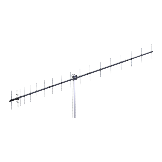
Model ......................................... 440-18X
Frequency Range ....................... 420 To 450 MHz
*Gain .......................................... 16.5 dBi
Front to back .............................. 24 dB Typical
Beamwidth ............................... E=27° H=32°
Feed type ................................... Folded Dipole
Feed Impedance. ....................... 50 Ohms Unbalanced
Maximum VSWR ........................ 1.5:1 Average
Input Connector .......................... "N" Female
FEATURES:
M2 is always trying to design and build new antennas to fit the needs of amateur radio operators. The "X" series of antennas are all designed
to keep the packaging under 48" long to minimize oversize surcharges applied by shippers. The "X" series antennas offer the same performance as its
predecessor, but with shorter boom sections. The boom sections also have a thicker wall for added strength. A side benefit of the "X" series antennas
are that they are more portable with the smaller sections.
The 440-18X replaces our very popular 440-18. The 440-18X is a computer optimized broadband yagi featuring an excellent pattern and good
gain across its bandwidth. It can be mounted vertically or horizontally and is ideal for stacking two or more for additional gain. Its light weight yet sturdy
construction keep the cost low and the performance high. Use it for ATV, OSCAR, FM, LONG HAUL TROPO, ETC. We guarantee you will be im-
pressed.
The heart of the 440-18X is a unique Driven Element Module with superior weather resistance and power handling abilities. All connectors are
O-ring sealed to the CNC machined block and internal connections are sealed in a space-age silicone gel with a dielectric strength nearly 4 times
greater than air. The Balun coax connectors are triple O-ring sealed. Other key mechanical and electrical parts are CNC machined from 6061-T6 alumi-
num and all hardware except U-bolts is stainless steel.
The 440-18X offers you uncompromising performance, enduring mechanical construction, and long term electrical integrity.
M2 Antenna Systems, Inc. 4402 N. Selland Ave. Fresno, CA 93722
M2 Antenna Systems, Inc.
Model No: 440-18X
*Subtract 2.14 from dBi for dBd
Tel: (559) 432-8873 Fax: (559) 432-3059 Web: www.m2inc.com
©2015 M2 Antenna Systems Incorporated
Power Handling .......................... 1.5 kW
Boom Length / Dia ...................... 135"' / 1" To 3/4"
Maximum Element Length .......... 14"
Turning Radius: .......................... 69'
Stacking Distance ....................... 51" High & 52" Wide
Mast Size .................................... 2"
Wind area / Survival ................... 0.68 Sq. Ft. / 100 MPH
Weight / Ship Wt. ........................ 5 Lbs. / 7 Lbs.
05/22/21
Rev.01
Advertisement
Table of Contents

Related Manuals for M2 Antenna Systems 440-18X


Summary of Contents for M2 Antenna Systems 440-18X
- Page 1 The heart of the 440-18X is a unique Driven Element Module with superior weather resistance and power handling abilities. All connectors are O-ring sealed to the CNC machined block and internal connections are sealed in a space-age silicone gel with a dielectric strength nearly 4 times greater than air.
- Page 2 440-18X ASSEMBLY MANUAL 1. Start by laying out the boom sections using the DIMENSION sheet as a guide. Use 8-32 X 1-1/4 screws and locknuts to join sections. Sections may be swaged to fit each other or use short internal splice sections.
- Page 3 440-18X ASSEMBLY MANUAL 7. Attach balun and tighten the connectors gently using a 7/16" end wrench. A lot of torque is unnecessary. Form the balun close to the boom and secure to boom with a nylon cable tie. Tie should be snug but not crushing or kinking the coax.
- Page 4 440-18X DIMENSION SHEET BTM PLATE POSITION ANTENNAS CENTER OF BALANCE 52.00” FROM THE REAR OF ANTENNA...
- Page 5 440-18X PARTS & HARDWARE DESCRIPTION BOOM SECTION, 1 X .065 X 37-3/4” SOE(M2ABS44018X-1) ....1 BOOM SECTION, 1 X .065 X 37-3/4” SOE(M2ABS44018X-2) ....1 BOOM SECTION, 1 X .065 X 37-3/4” SOE(M2ABS44018X-3) ....1 BOOM SECTION, 3/4 X .049 X 27-3/4”(M2ABS44018X-4) ......1 ELEMENTS, 3/16 ROD x DIMENSION SHEET ...........
Need help?
Do you have a question about the 440-18X and is the answer not in the manual?
Questions and answers