Table of Contents
Advertisement
Quick Links
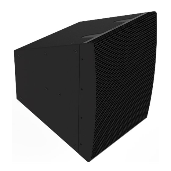
Community L Series
LVH-900 Beamforming Venue Horn
Installation & Operation Guide
PRODUCT DESCRIPTION
Biamp's Community L SERIES LVH-900 Beamforming Venue
Horn, combined with the Community Amplified Loudspeaker
Controllers (ALCs), precisely tailor the directivity of each
loudspeaker, or array of loudspeakers, to meet the sound
requirements in any application.
Designed for exceptional performance in large venues,
each LVH-900 model consists of four 12-inch LF drivers,
three Community M200E midrange compression drivers
and four 1.5-inch HF compression drivers. Using patent-
pending techniques, all drivers integrate into a single triaxial
waveguide that fills the entire 36 x 31-inch face of the
enclosure, providing pattern control to below 400 Hz. The
LVH-900 models offer 60 or 90 degrees of fixed horizontal
dispersion.
The LVH-900 Active Standard (AS) models allow DSP
settings and control of individual driver pairs to provide
uniform sound to the audience areas. The LVH-900/AS
models have presets for vertical dispersion beamforming in
60°, 40°, 20° configurations.
A:
Models
LVH-906/AS
LVH-909/AS
LVH-906/AP
LVH-909/AP
9300 S.W. Gemini Drive Beaverton, OR 97008 USA
The LVH-900 Active-Plus (AP) models use advanced
FIR techniques to seamlessly combine the output of two
loudspeakers into one coherent wavefront, providing higher
output or wider coverage patterns. LVH-900/AP models
have presets for vertical dispersion beamforming in 100°,
80°, 20° configurations.
Typical applications include music and speech reinforcement
for large houses of worship, stadiums, theaters, and much
more. Possessing advanced features, highly-focused
dispersion patterns, weather-resistant construction, and
most importantly sonic excellence, LVH-900 loudspeakers
make installations not only fast and simple, but as functionally
effective as possible.
FEATURES
• Designed for extraordinary performance in large
venues
• Large format, horn-loaded triaxial design maintains
pattern control to below 400Hz
• Co-linear manifold for HF and MF beamforming
• Indoor or Outdoor weather-resistant (WR) models
W:
www.biamp.com
Advertisement
Table of Contents

Subscribe to Our Youtube Channel
Related Manuals for Biamp L Series


Summary of Contents for Biamp L Series
- Page 1 PRODUCT DESCRIPTION The LVH-900 Active-Plus (AP) models use advanced FIR techniques to seamlessly combine the output of two Biamp's Community L SERIES LVH-900 Beamforming Venue loudspeakers into one coherent wavefront, providing higher Horn, combined with the Community Amplified Loudspeaker output or wider coverage patterns. LVH-900/AP models Controllers (ALCs), precisely tailor the directivity of each have presets for vertical dispersion beamforming in 100°,...
-
Page 2: Product Representation
IMPORTANT: Please note any application restrictions (Indoor vs Outdoor) on the rigging accessories shown in this installation guide. Rear Contact Biamp for information regarding mounting options for multi- cabinet WR (outdoor) LVH loudspeakers. RIGGING AND ELECTRICAL SAFETY IMPORTANT: The loudspeakers described in this manual are... -
Page 3: Installation Preparation
® ® here)*. The latest LVH-900 GLL (loudspeaker file) is available on the Biamp website (here) The report generated will dictate the models, splay plate types and quantities needed. The WR (weather-resistant) models are designed to comply with, and pass IEC 60068-2-5 Solar Radiation, IEC 60068-2-11... -
Page 4: Mounting Points
They are not rigging points and are necessary for cabinet integrity. For the same reason, do not remove the plugs on the curved side panels or the bolts in the Community trim bars. page 4 Installation and Operation Guide L SERIES LVH-900... - Page 5 LVH-900/AP Dual cabinet arrays should be configured using the following splay plates and hole sets. 10° LVH-900/AP 20° LVH-900/AP 80° LVH-900/AP 100° SP2 - 30° Back Splay SP1 - 0° Back Splay SP1 - 10° Front Splay L SERIES LVH-900 Installation and Operation Guide page 5...
- Page 6 Figure 1. Cabinet to Splay Bracket attachment points to achieve splay angles suggested in EF3 M10 Flat Washer M10 Hex Bolt Figure 2. Attach splay bracket to each side of the loudspeaker Use correct holes to attain desired angle - keep connections loose page 6 Installation and Operation Guide L SERIES LVH-900...
- Page 7 Back Splay Back Splay Front Splay 20° hole set 0° hole set 10° hole set Figure 4. Typical splay bracket orientation - cabinet connection locations are symmetrical on the splay bracket L SERIES LVH-900 Installation and Operation Guide page 7...
- Page 8 (black and stainless steel) - use the appropriate hardware for indoor (black) or outdoor (SS). LVH-900/AP Dual 20° Array M10 Flat Washer M10 Hex Bolt Figure 5. Loosely attach splay bracket page 8 Installation and Operation Guide L SERIES LVH-900...
- Page 9 Figure 6. Attach the side plate to the next cabinet - keep all connections LOOSE until all bolts are started. Support the second cabinet until all connections are made and tightened L SERIES LVH-900 Installation and Operation Guide page 9...
- Page 10 Note: The levers are stiff: take care when lifting or pressing them down. example Input Panel LVH-900/AS page 10 Installation and Operation Guide L SERIES LVH-900...
- Page 11 Junction box ALC-1604D (L1) (bridged) Ch 3 & 4 bridged + – (L2) + – LF 2 LF 1 + – + – 4-conductor Figure 7. Wiring for LVH-900/AS Input Panel L SERIES LVH-900 Installation and Operation Guide page 11...
- Page 12 Note: The levers are stiff: take care when lifting or pressing them down. LF Input Panel LVH-900/AP MF/HF Input Panel LVH-900/AP page 12 Installation and Operation Guide L SERIES LVH-900...
-
Page 13: Top Cabinet
MF 2 MF 3 – – – – – Biamp and Community are trademarks of Biamp and its Biamp a liates, registered in various countries around the world Patent: www.biamp.com/patents 9300 S.W. Gemini Drive Beaverton, OR 97008 USA 6-conductor 8-conductor Bottom Cabinet biamp.com... - Page 14 Tip: Secure the harness to an interior support with a cable tie to prevent it Figure 9. Remove both input panels from moving around during operation. Figure 10. Thread harness through openings page 14 Installation and Operation Guide L SERIES LVH-900...
- Page 15 - bottom). This is useful for WR models - 3 gland nuts would be needed. Active panel LVH-900ASPTP panel Figure 11. Plug into panels Socket Head Screws 5mm Flat Washer Figure 12. Place and reattach panels L SERIES LVH-900 Installation and Operation Guide page 15...
-
Page 16: Installation & Wiring
Junction box ALC-1604D (L1) (bridged) Ch 3 & 4 bridged + – (L2) + – 4-conductor LF 2 LF 1 + – + – 4-conductor Separate cables for MF & HF connections page 16 Installation and Operation Guide L SERIES LVH-900... -
Page 17: Cover Installation
HF or MF Figure 13. Attach cover to input panel - 10 screws/panel. sections. Installation instructions Note: gland nuts are not provided for that panel is on pages 14-15 of this manual. L SERIES LVH-900 Installation and Operation Guide page 17... -
Page 18: Eyebolt Installation
1/2" Flat Washer 1/2" Stover Nut Attach eyebolts in appropriate top holes Do NOT use the side holes in the spine for eyebolts page 18 Installation and Operation Guide L SERIES LVH-900... - Page 19 Place PY1 on the spine closest to the pinpoint (CoG) and align with designated side holes Hex Nut Carriage Hex Bolt Locking Ring Attach with carriage bolt and hex nut, and secure with the locking ring L SERIES LVH-900 Installation and Operation Guide page 19...
- Page 20 4. Tighten to torque values below - Do not over-tighten! Hardware Torque Setting 10mm bolts: 50Nm (36.88 ft-lbs) Hardware removed M10 Hex Head Bolt M10 Flat Washer Attach array frame to the cabinet Array frame attached page 20 Installation and Operation Guide L SERIES LVH-900...
- Page 21 Pull Back Frame (LVH-900PB) When required, a secondary safety cable can be Pull back bar attached attached to an unused hole(s) on the center tab. L SERIES LVH-900 Installation and Operation Guide page 21...
- Page 22 Kit Weight: 30.7 lbs (13.9 kg) Working Load Limit: 250 lbs (113.4 kg) (10:1 safety factor) The technical drawings including dimensions and hole diameters are on page 28 of this guide. page 22 Installation and Operation Guide L SERIES LVH-900...
- Page 23 30° of rotation (5° to 35° aiming down) Shown mounted in LVH-909 CoG Regular mounting position with 100° Attach U-Bracket and set the angle of rotation (-5°to 95° aiming down) Shown mounted in LVH-909 CoG L SERIES LVH-900 Installation and Operation Guide page 23...
- Page 24 TECHNICAL DRAWINGS - LVH-900 CABINET page 24 Installation and Operation Guide L SERIES LVH-900...
- Page 25 DIMENSIONS ARE IN MM THE INFORMATION DISCLOSED HEREIN WAS TOLERANCES: ORIGINATED BY AND IS THE PROPERTY OF TITLE: BIAMP SYSTEMS AND EXCEPT FOR THE ANGULAR: 1 ° LVH-900SP2 Splay Bracket Type 2 RIGHTS EXPRESSLY GRANTED TO THE UNITED MINIMUM FIRST ARTICLE REQUIREMENT...
- Page 26 TECHNICAL DRAWINGS - RIGGING (continued) LVH-900AF Array Frame page 26 Installation and Operation Guide L SERIES LVH-900...
- Page 27 TECHNICAL DRAWINGS - RIGGING (continued) LVH-900PB Pull Back Bar L SERIES LVH-900 Installation and Operation Guide page 27...
- Page 28 TECHNICAL DRAWINGS - RIGGING (continued) LVH-900UB U-Bracket page 28 Installation and Operation Guide L SERIES LVH-900...
- Page 29 Custom Length Ceiling Extension Post (available from 2ft. to 16ft.) All PY0/PY1 brackets shown are infinitely adjustable, and will connect to the carriage hang points on the LVH-AF. Rigging images courtesy of Polar Focus Rear cable channel L SERIES LVH-900 Installation and Operation Guide page 29...
- Page 30 APPENDIX page 30 Installation and Operation Guide L SERIES LVH-900...
- Page 31 APPENDIX (continued) L SERIES LVH-900 Installation and Operation Guide page 31...
- Page 32 APPENDIX (continued) page 32 Installation and Operation Guide L SERIES LVH-900...
- Page 33 APPENDIX (continued) Installation and Operation Guide L SERIES LVH-900 page 33...
-
Page 34: Warranty
CONTACT US Email: support@biamp.com communitysupport@biamp.com Web: support.biamp.com Warranty: biamp.com/legal/warranty-information Note: Every effort has been made to ensure that the information contained in this manual was complete and accurate when printed. However, due to ongoing technical advances, changes or modifications may have occurred that are not covered in this manual.
Need help?
Do you have a question about the L Series and is the answer not in the manual?
Questions and answers