Advertisement
Quick Links
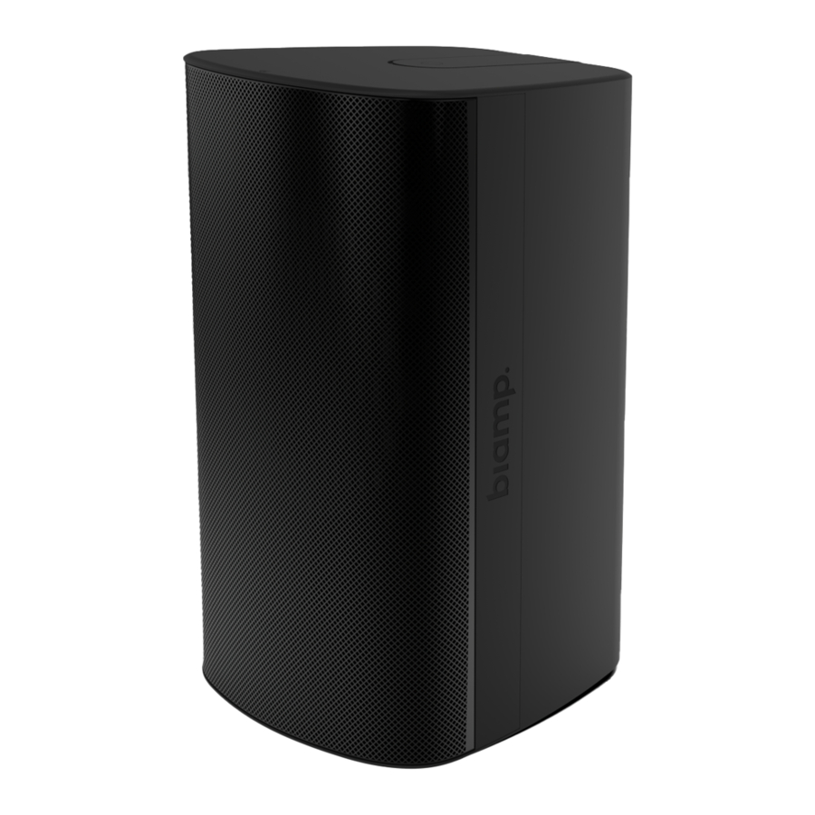
Desono™
EX Surface Mount Loudspeakers
Installation & Operation Guide
PRODUCT DESCRIPTION
The Desono™ EX product family includes three two-way
full-range and one subwoofer surface-mount loudspeaker
designs. They deliver excellent musicality and high
intelligibility with deep extended bass response and wide,
conical coverage patterns.
The loudspeakers are designed to be used in both indoor
and outdoor environments and share attractive modern
aesthetic styling. The loudspeakers can be mounted with
our innovative ClickMount™ pan-tilt system than provides
indexed aiming control. A ClickMount U-Bracket also is
available for low profile mounting to a structure.
A:
9300 S.W. Gemini Drive Beaverton, OR 97008 USA
FEATURES
• Three sizes to deliver exceptional audio clarity with
small footprints
• Uniform coverage from coaxially mounted HF/LF
drivers
• A companion subwoofer for additional high SPL low
frequencies
• 5-position tap for 70V/100V systems with low
impedance bypass
• ETL listed to comply with UL 1480A, and is RoHS
compliant
• Pending CSA 62368-1, EN54-24, ISO 7240-24 (ROW)
and CE certification for full-range models
Models
EX-S6
EX-S8
EX-S10
EX-S10SUB
W:
www.biamp.com
Advertisement

Related Manuals for Biamp Desono EX Series


Summary of Contents for Biamp Desono EX Series
- Page 1 A ClickMount U-Bracket also is • Pending CSA 62368-1, EN54-24, ISO 7240-24 (ROW) available for low profile mounting to a structure. and CE certification for full-range models 9300 S.W. Gemini Drive Beaverton, OR 97008 USA www.biamp.com...
-
Page 2: Product Representation
CAUTION: Installation of Biamp loudspeakers should only methods. Installation of loudspeakers should only be performed be performed by trained and qualified personnel. It is by trained and qualified personnel. -
Page 3: Installation
INSTALLATION The loudspeaker can be mounted to a variety of surfaces, but must be mounted to structural load bearing surfaces or substrates (not electrical gang boxes). There are two mounting options provided for the Desono EX family of loudspeakers: a ClickMount pan-tilt bracket and an indexing U-Bracket with included waterproof ClickPlug wiring insert. - Page 4 Installation - ClickMount Pan-tilt Bracket (continued) Adjust the Tap Switch 4. The tap switch should be adjusted before you attach the speaker to the bracket. Rotate the switch to the desired setting (Figure 4). Figure 4. Rotate tap switch Attach the loudspeaker to the bracket NOTES: If you know the desired aiming angle of the loudspeaker, the ClickMount bracket can be adjusted before attaching the loudspeaker.
- Page 5 Installation - ClickMount Pan-tilt Bracket (continued) 6. Secure the loudspeaker with a safety cable attached to the loop on the rear. The cable should be mounted to a secondary mounting point close NOTE: The installer is responsible for to the bracket to avoid any kinetic force if the wall mount should fail, or sourcing the proper safety cable to meet all applicable local building codes and the latch be released without the loudspeaker being supported.
- Page 6 Installation - ClickMount Pan-tilt Bracket (continued) To remove loudspeaker from the bracket WARNING: When you release the clickmount latch - the The loudspeaker can be removed from the ClickMount pan-tilt bracket as follows: loudspeaker will fall off the 1. Insert a 5mm hex wrench into the hole within the slot in the middle of the ClickMount bracket! Fully support the label on the rear panel (Figure 8a).
- Page 7 ClickMount Pan-tilt Aiming Angles (Small Bracket EX-S6) Portrait [Vertical] Orientation Top View Side View Tilt Up 24° (3 clicks) 8° increments Pan Left 60° (5 clicks) 12° increments Pan Right 60° (5 clicks) 12° increments Tilt Down 32° (4 clicks) 8°...
- Page 8 ClickMount Pan-tilt Aiming angles (Large Bracket EX-S8) Portrait [Vertical] Orientation Top View Side View Tilt Up Pan Left 24° (3 clicks) 60° (5 clicks) 8° increments 12° increments Pan Right 60° (5 clicks) Tilt Down 12° increments 32° (4 clicks) 8°...
- Page 9 ClickMount Pan-tilt Aiming angles (Large Bracket EX-S10, EX-S10SUB) Portrait [Vertical] Orientation Top View Side View Tilt Up Pan Left 24° (3 clicks) 60° (5 clicks) 8° increments 12° increments Tilt Down Pan Right 24° (3 clicks) 60° (5 clicks) 8° increments 12°...
- Page 10 Installation - U-Bracket The U-Bracket is a low profile powder-coated Marine Grade aluminum design that allows the unit to be connected to a center suspension post or against the wall, ceiling or other flat surface. It can also be mounted to a variety of third party stand and pole adapters.
- Page 11 Installation - U-Bracket (continued) Attach the Loudspeaker to the U-Bracket 4. The loudspeaker must be mounted in a specific way to allow the ClickMount teeth on the U-Bracket to guide the speaker perfectly into place using the IMPORTANT: The cabinet is finished shallow channels on each end of the speaker.
- Page 12 Installation - U-Bracket (continued) Adjust the Tap Switch 7. The tap switch should be adjusted before you attach the ClickPlug to the loudspeaker. Rotate the switch to the desired setting (Figure 11). Figure 11. Rotate tap switch Attach the ClickPlug 8.
-
Page 13: Attach Safety Cable
Installation - U-Bracket (continued) The ClickPlug should be oriented as shown below. It can not be installed upside- down (Figure 13). NOTE: At some landscape orientation down angle points, the ClickPlug gland nut and U-Bracket will interfere with each other. In these instances, the ClickPlug needs to be rotated 90 degrees to provide clearance for the U-Bracket rotation. - Page 14 Remove ClickPlug from the Loudspeaker The ClickPlug can be removed from the loudspeaker as follows: CAUTION: The ClickPlug fit is 1. Insert a 5mm hex wrench into the hole within the slot in the middle of the very tight and is difficult to label on the rear panel (Figure 12a).
- Page 15 END CAP COVERS The end cap covers can be removed if you purchased a unit with a ClickMount pan-tilt bracket and need to change it to a U-Bracket mount with the addition of an Tools Needed accessory UB kit. If you purchased a UB model and need to change to a pan-tilt bracket, the covers can be reattached starting at Step 5 •...
- Page 16 End Cap Covers (continued) Cover Attachment (Figure 17) 5. Slide cover on and seat over the threaded insert. 6. Screw on the cover retention nut with the 6mm hex wrench. 7. Cover the nut with the small cap - insert the rear tabs first, then push down the front to fully seat.
- Page 17 EYEBOLT SUSPENSION (OPTIONAL) Tools/Hardware Needed EX loudspeakers can be suspended by • Rated M10 Eyebolt a single shouldered eyebolt and have shaft length 0.75 (20mm) the angle adjusted with a secondary • 5 mm hex wrench (latch release) cable attached to the safety cable WARNING: The wiring to the ClickPlug location.
-
Page 18: Painting Instructions
PAINTING INSTRUCTIONS The Desono EX cabinets have a light paint coat over the CAUTION: NEVER use abrasives, gasoline, plastic material. They accept almost any type of latex or kerosene, acetone, methyl ethyl ketone (MEK), paint enamel (oil based) paint. We recommend application of two thinner, harsh detergents or other chemicals on the light coats. - Page 19 Painting Instructions (continued) Loudspeaker preparation 2. Fully mask the full (black) loudspeaker face so that all internal components will not receive any paint. Also mask off the rear input panel (area around the tap switch) the retaining latch for the mounts, the rear label and latch access (Figure 20).
- Page 20 TECHNICAL DRAWINGS - CLICKMOUNT PAN-TILT BRACKET CMX-SM Hardware: 1/4-20 or 6mm screw for attachment, Backplate will accept typical 1/2" or 13mm socket (18mm OD) page 20 Installation and Operation Guide Desono EX-S...
- Page 21 TECHNICAL DRAWINGS - U-BRACKETS EXUB-S6 Desono EX-S Installation and Operation Guide page 21...
- Page 22 CONTACT US Email: support@biamp.com Web: support.biamp.com Warranty: biamp.com/legal/warranty-information Safety & Compliance: biamp.com/compliance Note: Every effort has been made to ensure that the information contained in this manual was complete and accurate when printed. However, due to ongoing technical advances, changes or modifications may have occurred that are not covered in this manual.
Need help?
Do you have a question about the Desono EX Series and is the answer not in the manual?
Questions and answers