
Subscribe to Our Youtube Channel
Related Manuals for Parker Parflange ECO 25


Summary of Contents for Parker Parflange ECO 25
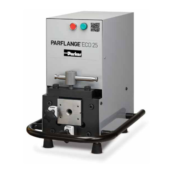
- Page 1 Parflange ECO 25 Hydraulic Flanging and Flaring Tool Operation Manual Bulletin 4391 - ECO25 October 2019...
- Page 2 Offer of Sale The items described in this document are hereby offered for sale by Parker Hannifin Corporation, its subsidiaries or its authorized distributors. This offer and its acceptance are governed by the provisions stated in the “Offer of Sale.”...
-
Page 3: Table Of Contents
Parflange ECO 25 Hydraulic Flanging and Flaring Tool Table of Contents Features and Advantages ...................4 ECO 25 Specifications ..................5 Setup Instructions ....................5 Tube End Preparation ..................6 90˚ Flanging Information for Seal-Lok Fittings ........... 7-13 37˚ Flaring Information for Triple-Lok Fittings .......... 14-20 Offer of Sale .......................21... -
Page 4: Features And Advantages
The ECO 25 is capable of completing 90° flanges on steel and allowing it to be utilized virtually anywhere. stainless steel tubing from ¼” through 1½” outside diameters for use with O-ring Face Seal tube fittings, such as Parker Seal-Lok ™ Hand Pump 37˚... -
Page 5: Eco 25 Specifications
Parflange ECO 25 Hydraulic Flanging and Flaring Tool ECO 25 Specifications Height 20.5 in. (520 mm) Width 15 in. (381 mm) Depth 20.5 in. (520 mm) Weight 190 lbs. (86.4 kg) Electrical Requirements 110 Volt, 1 phase, 60Hz/20A Motor 1.5 HP Maximum Pump Flow 20 in. -
Page 6: Tube End Preparation
Parflange ECO 25 Hydraulic Flanging and Flaring Tool Tube End Preparation Tube end preparation is one of the most critical processes in obtaining an optimum seal of a flanged or flared tube end con- nection. Regardless of the tube material, similar guidelines for tube cut-off, deburring, and cleanliness can help assure the tube to fitting connection remains leak free. -
Page 7: 90˚ Flanging Information For Seal-Lok Fittings
Parflange ECO 25 Hydraulic Flanging and Flaring Tool 90˚ Flanging Information for Seal-Lok Fittings Flanging Die Set, Inch Sizes Flanging Pin, Inch Sizes Wall Tube O.D. Thickness Flanging Pin Flanging Pin Tube O.D. Die Set Steel Tube Stainless Tube (in.) Part Number (in.) - Page 8 Parflange ECO 25 Hydraulic Flanging and Flaring Tool 90˚ Flanging Information for Seal-Lok Fittings Parflange ECO 25 Dial Settings and Pressures for 90˚ Flanging Steel Tube Stainless Steel Tube Wall Flanging Flanging Tube O.D. Thickness Tube Stop Head Stop Pressure...
- Page 9 Parflange ECO 25 Hydraulic Flanging and Flaring Tool 90˚ Flanging Information for Seal-Lok Fittings Components Required • Dual-Function Flare/Flange Die Set (contains tooling for both Flanging and Flaring) See chart page 7 • Flanging Pin specific to Tube O.D., Wall Thickness, and Tube...
- Page 10 Parflange ECO 25 Hydraulic Flanging and Flaring Tool 90˚ Flanging Information for Seal-Lok Fittings Step 4: Raise the tube stop and install the flanging pin into the main spindle head of the machine. Be sure to lower the tube stop to its original position after inserting the pin.
- Page 11 Parflange ECO 25 Hydraulic Flanging and Flaring Tool 90˚ Flanging Information for Seal-Lok Fittings Step 10: Set Head Stop adjustment dial to recommended value for flanging the O.D., wall thickness and material of the tubing you are using (See Chart on page 8). Dial settings are recommendations only and may require adjustment to obtain desired results.
- Page 12 Parflange ECO 25 Hydraulic Flanging and Flaring Tool 90˚ Flanging Information for Seal-Lok Fittings Step 16: When the pressure gauge reaches the recommended flanging pressure from Step 13, de-energize the hy- draulic power supply. This will allow the flanging pin and spindle head to retract to their original position.
- Page 13 Parflange ECO 25 Hydraulic Flanging and Flaring Tool 90˚ Flanging Information for Seal-Lok Fittings Step 21: Inspect flange to ensure proper surface finish. Mea- sure the flange diameter and compare to values in chart below. Adjusting the ECO 25 to compensate for...
-
Page 14: 37˚ Flaring Information For Triple-Lok Fittings
Parflange ECO 25 Hydraulic Flanging and Flaring Tool 37˚ Flaring Information for Triple-Lok Fittings Flaring Die Sets, Inch Sizes Flaring Pins, Inch Sizes Wall Tube Tube O.D. Thickness Flaring Pin Fitting O.D. Die Set (in.) (in.) Part Number Dash Size (in.) - Page 15 Parflange ECO 25 Hydraulic Flanging and Flaring Tool 37˚ Flaring Information for Triple-Lok Fittings Parflange ECO 25 Dial Settings and Pressures for 37˚ Flaring Steel Tube Stainless Steel Tube Wall Flaring Flaring Tube O.D. Thickness Tube Stop Head Stop Pressure...
- Page 16 Parflange ECO 25 Hydraulic Flanging and Flaring Tool 37˚ Flaring Information for Triple-Lok Fittings Components Required • Dual-Function Flare/Flange Die Set (contains tooling for both Flanging and Flaring) See chart page 14 • Flaring Pin specific to Tube O.D. and Wall Thickness...
- Page 17 Parflange ECO 25 Hydraulic Flanging and Flaring Tool 37˚ Flaring Information for Triple-Lok Fittings Step 4: Raise the tube stop and install the flaring pin into the main spindle head of the machine. Be sure to lower the tube stop to its original position after inserting the pin.
- Page 18 Parflange ECO 25 Hydraulic Flanging and Flaring Tool 37˚ Flaring Information for Triple-Lok Fittings Step 10: Insert the tube through the die set until it touches the tube stop. You may have to raise the upper die half slightly to allow the tube to fully insert through the die set.
- Page 19 Parflange ECO 25 Hydraulic Flanging and Flaring Tool 37˚ Flaring Information for Triple-Lok Fittings Step 16: When the pressure gauge reaches the recommended flaring pressure from Step 13, de-energize the hydraulic power supply. This will allow the flaring pin and spindle head to retract to their original position.
- Page 20 Parflange ECO 25 Hydraulic Flanging and Flaring Tool 37˚ Flaring Information for Triple-Lok Fittings Step 21: Inspect the flare to ensure proper surface finish. Mea- sure the flare diameter and compare to values in chart below. Adjusting the ECO 25 to compensate for...
-
Page 21: Offer Of Sale
Products. the date of discovery. Seller: m eans Parker-Hannifin Corporation, including all divisions and businesses thereof. 7. LIMITATION OF LIABILITY. IN THE EVENT OF A BREACH OF WARRANTY, Services: means any services to be supplied by the Seller. - Page 22 Parflange ECO 25 Offer of Sale Hydraulic Flanging and Flaring Tool Quote and these Terms, the terms set forth in the main body of the Quote shall of Buyer; (c) Seller’s use of patterns, tooling, equipment, plans, drawings, prevail. All prior or contemporaneous written or oral agreements or negotiations designs or specifications or other information or things furnished by Buyer; (d)
- Page 23 Parflange ECO 25 Hydraulic Flanging and Flaring Tool Notes Parker Hannifin Corporation Tube Fittings Division Columbus, Ohio http://www.parker.com/tfd...
- Page 24 For information, call toll free... (52) 722 2722 168 1-800-C-PARKER (1-800-272-7537) © 2019 Parker Hannifin Corporation Bulletin 4391-ECO25 Parflange is a registered trademark of Parker Hannifin Corporation. Parker Hannifin Corporation Tube Fittings Division 3885 Gateway Blvd. Columbus, OH 43228 phone 614 279 7070 fax 614 279 7868 e-mail TFDmailbox@Parker.com...
Need help?
Do you have a question about the Parflange ECO 25 and is the answer not in the manual?
Questions and answers