Table of Contents
Advertisement
Quick Links
Advertisement
Table of Contents

Related Manuals for Zimmer GSI Series


Summary of Contents for Zimmer GSI Series
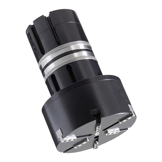
- Page 1 INSTALLATION AND OPERATING INSTRUCTIONS Handling technology GSI series O-ring assembly gripper pneumatic THE KNOW-HOW FACTORY Zimmer GmbH Im Salmenkopf 5 77866 Rheinau, Germany Phone: + 49 7844 9138-0 Fax: + 49 7844 9138-80 www.zimmer-group.de ● ● ● ● ●...
-
Page 2: Table Of Contents
INSTALLATION AND OPERATING INSTRUCTIONS: Pneumatic GSI series O-Ring gripper Contents: Supporting documents ..........................Proper use ..............................Personnel qualifications .......................... Function ..............................O-ring installation technological process ....................Flow chart ..............................Technical data ............................Installation ..............................Installing the gripper ..........................Power supply .............................. -
Page 3: Supporting Documents
Zimmer GmbH accepts no liability for any damage caused by improper use. The gripper is designed exclusively for pneumatic operation. The gripper is not suited for operation with any other media. The gripper is used as defined under "Proper use"... -
Page 4: O-Ring Installation Technological Process
INSTALLATION AND OPERATING INSTRUCTIONS: Pneumatic GSI series O-Ring gripper O-ring installation technological process 1 Home position .................► Spread jaws Home position retracted Clamping jaws Home position extended Ejector Home position retracted The gripper is ready to pickup an O-ring 2 Clamping ..................►... -
Page 5: Flow Chart
INSTALLATION AND OPERATING INSTRUCTIONS: Pneumatic GSI series O-Ring gripper Flow chart Information: Be sure to observe the description of the pneumatic connections in Chapter 6.2 "Power Supply." Space out Position the Re-press Action on the O-ring: Pick up O-ring evenly... -
Page 6: Installation
INSTALLATION AND OPERATING INSTRUCTIONS: Pneumatic GSI series O-Ring gripper Installation Installing the gripper The gripper is fastened via the 3 tapped holes •Screws with a screw class of 8.8 are to be used. •Permitted tightening torque The orientation is determined using straight pins in both... -
Page 7: Installing The Jaw Set
INSTALLATION AND OPERATING INSTRUCTIONS: Pneumatic GSI series O-Ring gripper Installing the jaw set The jaw set consists of 3 component groups. The expanding and clamping jaws as well as the corresponding wiper are designed differently depending on the size of the O-rings to be installed. - Page 8 INSTALLATION AND OPERATING INSTRUCTIONS: Pneumatic GSI series O-Ring gripper ► Inserting the centering rings prepares the gripper jaws for the installation of the spread jaw. Clamping jaws ► Reduce stroke to the minimum dimension (as described in Chapter 6.3) ► Position the clamping jaws on the gripper jaws, •Pins in the direction of the wiper.
-
Page 9: Settings
INSTALLATION AND OPERATING INSTRUCTIONS: Pneumatic GSI series O-Ring gripper Settings Wiper: ► Move the clamping jaws together manually / press inward ► Align wiper so, that the clamping jaws can move in and out without contact. ► Secure the wiper in this position Clamping jaws: ►... -
Page 10: Position Sensing Sensors
INSTALLATION AND OPERATING INSTRUCTIONS: Pneumatic GSI series O-Ring gripper Spread jaws: ► Retract clamping jaws No interference contour when retracting them into the workpiece. ► Adjust the immersion depth of the spread jaws into the workpiece C ontact surface... -
Page 11: Troubleshooting
INSTALLATION AND OPERATING INSTRUCTIONS: Pneumatic GSI series O-Ring gripper Troubleshooting Issue Cause Remedies Is the O-ring position on the spread jaw correct after being picked up by the ► Check the pickup position gripper? ► Check the immersion depth of the... -
Page 12: Maintenance
If the requirements are not adhered to, the maintenance interval will be reduced according to the application case. NOTE: We recommend using the Zimmer GmbH repair service for maintenance and the replacement of seals. Dismantling and reassembling the gripper without authorization may result in complications as in some cases special installation equipment is required. -
Page 13: Declaration Of Incorporation
EU Machinery Directive 2006/42/EC (Appendix II 1 B) Name and address of the manufacturer: Zimmer GmbH, Im Salmenkopf 5, D-77866 Rheinau, Germany, Phone: +49 7844 91380, www.zimmer-group.de We hereby declare that the incomplete machines described below... -
Page 14: Your Notes
INSTALLATION AND OPERATING INSTRUCTIONS: Pneumatic GSI series O-Ring gripper Your notes Zimmer GmbH Im Salmenkopf 5 77866 Rheinau, Germany Phone: + 49 7844 9138-0 Fax: + 49 7844 9138-80 www.zimmer-group.de ● ● ● ● ●... - Page 15 INSTALLATION AND OPERATING INSTRUCTIONS: Pneumatic GSI series O-Ring gripper Zimmer GmbH Im Salmenkopf 5 77866 Rheinau, Germany Phone: + 49 7844 9138-0 Fax: + 49 7844 9138-80 www.zimmer-group.de ● ● ● ● ●...
- Page 16 INSTALLATION AND OPERATING INSTRUCTIONS: Pneumatic GSI series O-Ring gripper Zimmer GmbH Im Salmenkopf 5 77866 Rheinau, Germany Phone: + 49 7844 9138-0 Fax: + 49 7844 9138-80 www.zimmer-group.de ● ● ● ● ●...
Need help?
Do you have a question about the GSI Series and is the answer not in the manual?
Questions and answers