Table of Contents
Advertisement
Available languages
Available languages
Quick Links
Advertisement
Table of Contents

Related Manuals for Honeywell Miller TurboLite MFL


Summary of Contents for Honeywell Miller TurboLite MFL
- Page 1 I267 Rev. C / MFP9720138 31 December 2013...
-
Page 2: Table Of Contents
Table of Contents 3.0 System Compatibility..............5-6 4.0 Making System Connections............ 7 5.0 Installation/Use................. 8-10 6.0 Calculating Fall Clearance Distance......... 10-12 7.0 Inspection and Maintenance............. 13-15 Miller Black Rhino™ Self-Retracting Lifelines..........48-49 Miller MiniLite® Fall Limiters............... 50-51 Miller Falcon™ Self-Retracting Lifelines............. 52-55 Miller MightyLite Self-Retracting Lifelines........... - Page 3 Us er In stru ctio ns - Engli sh Thank You WARNING All persons using this equipment must read, understand and follow all instructions. Failure to do so may result in serious injury or death. Do not use this equipment unless you are properly trained. Questions? 1.800.873.5242 1.0 Purpose...
- Page 4 Us er In stru ctio ns - Engli sh should be used in certain chemical or acidic or deterioration must be immediately discarded. a rescue plan and the means at hand to the manufacturer in cases of doubt. sources. The use of heat resistant materials is area to make sure potential fall path is clear.
-
Page 5: System Compatibility
Us er In stru ctio ns - Engli sh Never use the device as a restraint or pass inspection, or if the unit has been subjected to the forces of arresting a fall. positioning device. MAINTENANCE Do not attempt to service this device. If Do not lubricate this device. - Page 6 Us er In stru ctio ns - Engli sh 3.2 Component Warnings and Limitations ANCHORAGES/ANCHORAGE CONNECTORS or meet two. anchorages. anchorage strengths must be multiplied by the number of personal fall arrest systems attached to the anchorage. information provided with the connecting device to ensure that the anchorage point is at a height that will not allow a user to strike a lower level should a fall occur.
-
Page 7: Making System Connections
Us er In stru ctio ns - Engli sh 4.0 Making System Connections Connecting to the Body Support and Fig. 1b Anchorage/Anchorage Connector For general fall protection, connect the lifeline/lanyard end Connect the body of the retractable unit to the anchorage or anchorage sure connections are compatible in Fig. -
Page 8: Installation/Use
Fig. 4 is no slack in the lifeline when the unit is mounted above the user and connected to the user’s back D-ring. For non-overhead applications, please contact Honeywell Technical Service before proceeding.] 5.2 Tie-Back Installation Fig. 5 designed for such a connection. Refer to the I296... - Page 9 Us er In stru ctio ns - Engli sh 5.3 Installation in a Lift Application Fig. 6 the user’s harness in lift applications under the direction may exceed the maximum arresting force listed on the label; the top of the guardrail using self-retracting lifeline assistance when evaluating this installation application.
-
Page 10: Calculating Fall Clearance Distance
Us er In stru ctio ns - Engli sh 5.4 Installation for Horizontal Use CAUTION: relative technical letter before proceeding. 5.5 Installation in a Leading Edge Application Fig. 7 Refer to the I322 Leading Edge Self-Retracting Lifelines Instruction Supplement for complete information regarding this installation application. 6.0 Calculating Fall Clearance Distance It is essential to understand how to calculate the fall clearance distance for each work application to avoid contact with a lower level. - Page 11 Us er In stru ctio ns - Engli sh Minimum Required Fall Clearance from Work Level to Lower Level* When Working Directly Anchor Point In Standing In Potential Arrest Distance Crouched Position Position Swing Fall Position Position 5 ft (1.5m) 8 ft (2.4m) 10 ft (3.1m) 6 ft-3 in...
- Page 12 Fall clearance distance will increase according Honeywell Technical Services can help you calculate the added fall clearance required... call 1-800-873-5242 (press 4). Worker must not be exposed to a swing fall hazard.
-
Page 13: Inspection And Maintenance
Us er In stru ctio ns - Engli sh 7.0 Inspection and Maintenance 7.1 Operation and Inspection WARNING: The user must perform the following operation checkpoints and inspections prior to each use. In addition, a competent person must inspect equipment at regular intervals, at least annually.* *ANSI Z359.14 provides additional inspection requirements based on type of use and conditions of use. - Page 14 Us er In stru ctio ns - Engli sh Fig. 10a Inspect the load impact components before each use. Make sure that all labels and markings are present and legible. 7.1.1 Load Impact Indicators Fig. 10b Webbing Load Indicator exposed should the lifeline be subjected to fall arresting forces. Snap Hook Load Indicator This load indicator is built in to the snap hook and is located at fall arresting forces.
- Page 15 Us er In stru ctio ns - Engli sh Inspection Factory Type of Application Frequency Conditions of Use Authorized Competent Inspection Person Good storage to Light conditions, indoor or years but not longer Factory maintenance room temperature, clean by the manufacturer Moderate to Transportation, Fair storage conditions,...
-
Page 16: Objet
Instructions D’utilisation - Français Merci AVERTISSEMENT Toutes les personnes qui utilisent cet équipement doivent lire, compren- dre et suivre toutes les instructions. Tout manquement à cette règle peut avoir pour conséquence des blessures graves ou la mort. Ne pas utiliser cet équipement à moins d’avoir reçu une formation adéquate. Des Questions? 1.800.873.5242 les utilisateurs ont reçu une formation sur la manière appropriée d’installer, d’utiliser, d’inspecter et... - Page 17 Instructions D’utilisation - Français L’utilisateur doit posséder un plan de sau- objet susceptible de l’endommager, incluant de soudage, une source de chaleur, un une machine mobile. charge. de doute, consulter le fabricant. de chaleur. Dans de tels cas, on recommande en cas de chute est dégagé.
-
Page 18: Compatibilité Du Système
Instructions D’utilisation - Français ENTRETIEN et certains limiteurs de chute peuvent être de contaminants. tions fournies avec le système de ligne de vie ne passe pas l’inspection, ou si le dispositif a subi des contraintes d’arrêt de chute. d’une chute par balancement. devienne pas lâche. - Page 19 Instructions D’utilisation - Français 3.2 Instructions et Avertissements se Rapportant aux Composants ANCRAGES/CONNECTEURS D’ANCRAGE latéral. ÉQUIPEMENT DE PROTECTION INDIVIDUELLE pour un ajustement serré. DISPOSITIFS DE CONNEXION maximum] ne supporte jamais de charge. brutes ou coupantes ou encore d’éléments de structure de petit diamètre.
-
Page 20: Connexions Du Système
Instructions D’utilisation - Français 4.0 Connexions du Système Raccordement du soutien du corps et de l’ancrage/connecteur Fig. 1b d’ancrage dorsal en D sur le harnais intégral Raccorder le corps du dispositif Fig. 1a Fig. 2b le limiteur de le limiteur de chute individuel Fig. -
Page 21: Installation/Utilisation
à l’amarrage métallique dorsal de l’utilisateur. Pour les applications avec ancrage non vertical, veuillez communiquer avec le service technique d’Honeywell avant de continuer.] 5.2 Installation par Fig. 5 conçues de manière particulière pour permettre un ancrage. - Page 22 Instructions D’utilisation - Français 5.3 Installation pour une Application de Levage TRWS )] d’une personne compétente. une chute. Fig. 6 direction de toute chute possible. ces appareils ne sont pas installés au-dessus dans cette présent manuel d’instructions. application d’installation.
-
Page 23: Calcul De La Distance De Dégagement
Instructions D’utilisation - Français 5.4 Installation pour Utilisation Horizontale l’hypothèse d’une chute. 5.5 Installation dans une application de bord d’attaque Fig. 7 6.0 Calcul de la distance de la zone de dégagement en cas de chute Calcul de la zone de dégagement en cas de chute pour la ligne de vie autorétractable [Calcul effectué... - Page 24 Instructions D’utilisation - Français Zone de dégagement minimale requise en cas de chute en- tre la hauteur où est effectué le travail et le niveau inférieur* pas directement sous d’ancrage le point d’ancrage Distance d’arrêt accroupie ou debout de chutes balancement 5 pi (1,5m) 8 pi (2,44m)
- Page 25 Les Services techniques Honeywell peuvent ment vous aider à calculer la zone de dégagement supplémentaire requise en cas de chute ...composez le 1-800-873-5242 (appuyez sur le 4).
-
Page 26: Inspection Et Entretien
Instructions D’utilisation - Français 7.0 Inspection et Entretien 7.1 Fonctionnement et Inspection les inspections suivantes avant chaque usage. De plus, une personne compétente doit inspecter les équipements à intervalles réguliers, au moins une fois par an.* *La norme Z359.14 de l’ANSI fournit des exigences d’inspection supplémentaires en fonction du type d’utilisation et des conditions d’utilisation. - Page 27 Instructions D’utilisation - Français régulièrement. Fig. 10a 5. Indicateur d’impact de charge 7.1.1 Indicateurs D’impact de APRÈS Charge Fig. 10b Indicateur de charge de sangle chute Indicateur de charge de boucle à pression APRÈS Fig. 10c Indicateur de charge Karlstop selon l’illustration LES DISPOSITIFS QUI N’ONT PAS PASSÉ...
- Page 28 Instructions D’utilisation - Français Inspection Type d’inspection Conditions d’utilisation d’usage d’applications par une per l’usine Bonnes conditions de stock- age, utilisation en intérieur ou entretien d’usine ronnements propres par le fabricant Transport, Conditions de stockage cor- Semestrielle ou fort construction rectes, utilisation intérieure annuelle résidentielle,...
- Page 29 Instrucciones para El Usuario - Español Gracias ADVERTENCIA Toda persona que use este equipo debe leer, comprender y seguir cabalmente todas las instrucciones. No hacerlo podría tener como consecuencia lesiones graves o mortales. No use este equipo si no ha sido debidamente entrenado. ¿Consultas? 1.800.873.5242 integral de un programa completo de seguridad.
- Page 30 Instrucciones para El Usuario - Español El usuario debe contar con un plan y medios de rescate a mano para poder aplicarlos al soldadura, fuentes de calor, peligros eléctricos Debe protegerse todo el material sintético con el objeto de mantenerlo alejado de escorias, Consulte al fabricante en caso de dudas.
-
Page 31: Compatibilidad Del Sistema
Instrucciones para El Usuario - Español No permita que se ponga holgada la cu erda salvavidas. inspección, o si la unidad ha sido sujeta a Ne jamais utiliser le dispositif comme un dis positif de contrainte ou de positionnement. No intente dar servicio a este dispositivo. MANTENIMIENTO Si una cuerda salvavidas autorretráctil no funciona debidamente o necesita repararse,... - Page 32 Instrucciones para El Usuario - Español 3.2 Advertencias y Limitaciones con Respecto a los Componentes ANCLAJES/CONECTORES DE ANCLAJE ninguna carga en el linguete. APAREJO apretado. DISPOSITIVOS DE CONEXIÓN miento. cargas el linguete.
- Page 33 Instrucciones para El Usuario - Español 4.0 Cómo realizar las conexiones del sistema Realización de conexiones al so- porte del cuerpo y al anclaje/conec- Fig. 1b tore de anclaje Conecte el cuerpo de la unidad Fig. 1a conectores estén completamente cerrados y asegurados. Fig.
- Page 34 Fig. 4 sea montada sobre el usuario y conectada a la anilla en “D” trasera del mismo. Para aplicaciones que no sean en altura, comuníquese con el Servicio Técnico de Honeywell antes de proceder.] 5.2 Instalación de amarre posterior Fig. 5 amarre posterior de Miller son cuerdas de seguridad usuario amarrar a un anclaje de forma segura.
- Page 35 Instrucciones para El Usuario - Español 5.3 Instalación en Dispositivos de Elevación retráctiles Titan (modelos TRW/8FT y TRWS)] durante el uso deben ser lisos, redondeados o Fig. 6 mencionadas arriba puedan unirse abajo o a la altura de la del manual de instrucciones. obtener ayuda adicional cuando evalúe esta aplicación de instalación.
- Page 36 Instrucciones para El Usuario - Español 5.4 Instalación para Uso Horizontal del modelo de amortiguador SofStop 928LS de Miller conectado entre el anillo en forma de D del de proceder. 5.5 Instalación en una aplicación de avanzada Fig. 7 de los pies y mediante el cual la cuerda de seguridad tiene la usuario caiga.
- Page 37 Instrucciones para El Usuario - Español Margen de caída mínimo requerido desde el nivel de trabajo hasta el nivel inferior* Cuando trabaja directamente rectamente debajo del debajo del punto de anclaje punto de anclaje de frenadodel posición posición de posicióna arrodillada/ costada agachada...
- Page 38 Peligro de del margen de caída puede incrementarse caída con condiciones de caída con balanceo. balanceo Los Servicios Técnicos de Honeywell pueden ayudarle a calcular el margen de caída requerido… llame al 1-800-873-5242 (presione 4). El trabajador no debe estar expuesto a un peligro de caída con balanceo.
- Page 39 Instrucciones para El Usuario - Español 7.0 Inspección y Mantenimiento 7.1 Funcionamiento e Inspección ADVERTENCIA: El usuario debe desempeñar los siguientes puntos de control e inspecciones de operación antes de cada uso. Además, una persona competente debe inspeccionar el equipo a intervalos regulares, al menos anualmente.*. *ANSI Z359.14 provides additional inspection requirements based on type of use and conditions of use.
- Page 40 Instrucciones para El Usuario - Español Fig. 10a de usar la unidad inspeccione el indicador de impacto de componentes doblados, agrietados o deformados. marcas estén presentes y sean legibles. Indicadores de Impacto 7.1.1 de Carga Fig. 10b siguientes indicadores de impacto de carga Indicador de carga para tejido Indicador de carga para gancho de resorte Fig.
- Page 41 Instrucciones para El Usuario - Español Frecuencia Inspección Tipo de de inspección Condiciones de uso autorizada por la aplicación persona fábrica competente Rescate y Buenas condiciones de frecuente almacenamiento, uso a ligero nado, manten- interno o uso externo poco frecuente, tempera- tura ambiente, entornos fabricante limpios...
- Page 42 ................42-43 ..............44-45 ................46-47 Miller Black Rhino Self-Retracting Lifelines ..............48-49 Miller MiniLite Fall Limiters ..................... 50-51 Miller Falcon Self-Retracting Lifelines ................52-55 Miller MightyLite Self-Retracting Lifelines............... 56-59 ..................60 Titan Fall Limiters ........................ 61 Titan Self-Retracting Lifelines ..................62-63 ..................
- Page 43 User Instructions / Instructions D’utilisation / Instrucciones para El Usuario Contact manufacturer if instruction manual WARNING Manufacturer’s instructions supplied with this product at the time of shipment must be followed: wed: FAILURE TO DO SO MAY RESULT IN SERIOUS INJURY OR DEATH! SAFETY INSTRUCTIONS BEFORE USING: INSTALLATION:...
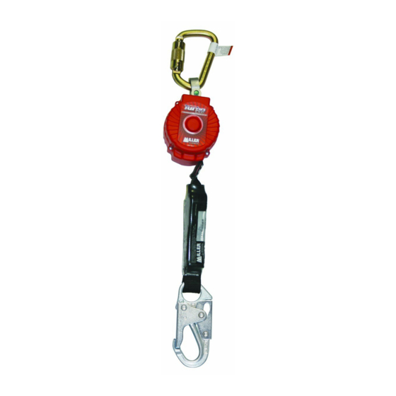
- Page 44 User Instructions / Instructions D’utilisation / Instrucciones para El Usuario Miller 9 ft. TurboLite ™ Personal Fall Limiters Weight Poids Peso 1 in x .06 in 2.3 lbs 4.68 in. 25,4mm x 1,52mm sangle 9 ft 3.6 lbs 25,4mm x 1,52mm tejido Models vary by unit connector and lanyard end connector.
- Page 45 User Instructions / Instructions D’utilisation / Instrucciones para El Usuario Contact manufacturer if instruction manual WARNING Manufacturer’s instructions supplied with this product at the time of shipment must be followed: FAILURE TO DO SO MAY RESULT IN SERIOUS INJURY OR DEATH! SAFETY INSTRUCTIONS BEFORE USING: INSTALLATION:...
- Page 46 User Instructions / Instructions D’utilisation / Instrucciones para El Usuario Miller Scorpion ™ Personal Fall Limiters Weight Poids Peso 1 in. x .06 in. 2.9 lbs. 25.4mm x 1.52mm sangle 9 ft. 25.4mm x 1.52mm tejido Models vary by unit connector and lanyard end connector. / Les modèles vari- ent de connecteur de l’unité...
- Page 47 User Instructions / Instructions D’utilisation / Instrucciones para El Usuario...
-
Page 48: Miller Black Rhino™ Self-Retracting Lifelines
User Instructions / Instructions D’utilisation / Instrucciones para El Usuario Miller Black Rhino ™ Self-Retracting Lifelines Weight Poids 6.53” Peso (165.9mm) 3/16 in. stainless steel 4.3 lbs. 5mm câble en acier 9 ft. inoxydable 5mm cable de acero inoxidable Models vary by unit connector and lanyard end connector. / Les modèles vari- ent de connecteur de l’unité... - Page 49 User Instructions / Instructions D’utilisation / Instrucciones para El Usuario...
-
Page 50: Miller Minilite® Fall Limiters
User Instructions / Instructions D’utilisation / Instrucciones para El Usuario Miller MiniLite ® Fall Limiters Weight Poids Peso cuerda 6.5” (165mm) FL11 1 in. x .06 in. 25.4mm x 1.52mm 11 ft. 2.5 lbs. sangle en polyes- 25.4mm x 1.52mm tejido de poliéster 3.75”... - Page 51 User Instructions / Instructions D’utilisation / Instrucciones para El Usuario Miller MiniLite ® FALL LIMITER Étiquette D’information Variable CLEAR WINDOW Tous les câbles de sécurité autorétractables et limiteurs de chute Miller comprennent tion, numéro d’inspection / de lot, longueur, LB343 et normes respectées par un modèle Rev.
-
Page 52: Miller Falcon™ Self-Retracting Lifelines
User Instructions / Instructions D’utilisation / Instrucciones para El Usuario Miller Falcon ™ Self-Retracting Lifelines 7.24” (184mm) 5.77” (146.6mm) 2.72” 21” (69mm) (533mm) WHEN FULLY RETRACTED Weight Poids Peso 310 lbs 16 ft 3.3 lbs 25mm sangle en polyester 20 ft 3.4 lbs 25mm sangle en polyester 54 in... - Page 53 User Instructions / Instructions D’utilisation / Instrucciones para El Usuario 24” (610mm) 28” WHEN (711mm) FULLY WHEN RETRACTED FULLY RETRACTED...
- Page 54 User Instructions / Instructions D’utilisation / Instrucciones para El Usuario...
- Page 55 User Instructions / Instructions D’utilisation / Instrucciones para El Usuario...
-
Page 56: Miller Mightylite Self-Retracting Lifelines
User Instructions / Instructions D’utilisation / Instrucciones para El Usuario Miller MightyLite Self-Retracting Lifelines Weight Poids Peso 20 ft. 8 lbs. 10.50 in. 6.38 in. 2.25 in. 25mm sangle en polyester 25mm tejido de poliéster 20 ft. 9 lbs. 10.50 in. 6.38 in. - Page 57 User Instructions / Instructions D’utilisation / Instrucciones para El Usuario 310 lbs 54 in 24 in 900 lbf 1800 lbf *when tested to ANSI Z359.14 / *lors d’essais conformément à la norme ANSI Z359.14 / *cuando es probado bajo ANSI Z359.14 **when tested to OSHA 1926.502 &...
- Page 58 User Instructions / Instructions D’utilisation / Instrucciones para El Usuario ™ PAT. NO. 5,771,993 Avg/Max Fall Arrest Force** 900 lbf/1800 lbf Max Total Arrest Distance 54 in [when tested to ANSI Z359.14**] (Distance Totale D’Arrêt Max) (1,4m) Max Fall Arrest Force** 900 lbf Max Free Fall Distance 24 in...
- Page 59 User Instructions / Instructions D’utilisation / Instrucciones para El Usuario ™ PAT. NO. 5,771,993 SPECIFICATIONS Max Total Arrest Distance 54 in (Distance Totale D’Arrêt Max) (1,4m) Max Free Fall Distance 24 in CLEAR WINDOW (Distance De Chute Libre Max) (0,6m) Max Capacity* 310 lbs (Capacite Max)
- Page 60 Expiration Date: See manual for inspection. Failure to do so may result in serious injury or death! MADE IN USA Contact Honeywell Safety Products if instruction manual is needed. AVERTISSEMENT: Vous devez respecter les ADVERTENCIA: Deben seguirse las instrucciones del...
-
Page 61: Titan™ Fall Limiters
User Instructions / Instructions D’utilisation / Instrucciones para El Usuario Titan ™ Fall Limiters Weight Poids Peso 11 ft 2.5 lbs 310 lbs Note: Dimensions are the same as the Mini- Lite Fall Limiters. Labels are also the same, with name and color exceptions. 39 in Remarque : Les dimensions sont les mêmes que les limiteurs de chute MiniLite. -
Page 62: Titan™ Self-Retracting Lifelines
User Instructions / Instructions D’utilisation / Instrucciones para El Usuario Titan ™ Self-Retracting Lifelines 310 lbs 54 in 24 in 900 lbf Refer to variable label for unit compliances. Prière de se reporter à l’étiquette variable pour les conformités d’unités. Consulte la etiqueta variable para ver el cumplimiento de normas de la unidad. - Page 63 User Instructions / Instructions D’utilisation / Instrucciones para El Usuario...
- Page 64 User Instructions / Instructions D’utilisation / Instrucciones para El Usuario Titan ™ Self-Retracting Lifeline Weight Poids Peso 20 ft 8 lbs 25,4mm x 1,52mm sangle en polyester 25,4mm x 1,52mm tejido de poliéster 310 lbs Note: Dimensions are the same as the MightyLite RL20 Self-Retracting Lifeline.
-
Page 65: Registre D'inspection Et D'entretien
User Instructions / Instructions D’utilisation / Instrucciones para El Usuario Titan Retractable ™ Web Lanyard fully retracted. Weight Poids Peso 1-3/4 in. x .06 in. 44.45mm x 1.52mm 8 ft. 2.5 lbs. sangle en polyester 44.45mm x 1.52mm tejido de poliéster 310 lbs 54 in 24 in... - Page 66 User Instructions / Instructions D’utilisation / Instrucciones para El Usuario NOTES / REMARQUES / NOTAS Variable Information Label Étiquette D’information Variable Tous les câbles de sécurité autorétractables et limiteurs de chute Miller comprennent aussi une modèle, date de fabrication, numéro d’inspection / de lot, longueur, et normes respectées par un Información Variable en Las Etiquetas NOTE: Compliance with standards varies by product model.
-
Page 67: Inspection And Maintenance Log
Inspection and Maintenance Log Registre D'inspection et D'entretien Registro de Inspección y Mantenimiento _________________________________________________ _________________________________________________________ ______________________________________________________... - Page 68 Inspection and Maintenance Log Registre D'inspection et D'entretien Registro de Inspección y Mantenimiento _________________________________________________ _________________________________________________________ ______________________________________________________...
- Page 69 ® BACKED BY OVER 65 YEARS IN THE FALL PROTECTION BUSINESS but are not indestructible and can be damaged by misuse. Should a product issue surface, contact us at 800.873.5242. ® ASSURÉE GRÂCE À PLUS DE 65 ANS PASSÉS DANS LE DOMAINE DE LA PROTECTION CONTRE LES CHUTES En cas de problème sur un produit, nous contacter au 800-873-5242.
Need help?
Do you have a question about the Miller TurboLite MFL and is the answer not in the manual?
Questions and answers