Honeywell TR50 User Manual
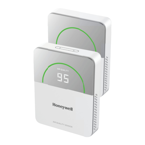
Indoor air quality sensor
Hide thumbs
Also See for TR50:
- User manual (93 pages) ,
- User instruction manual (70 pages) ,
- User manual (43 pages)
Table of Contents
Advertisement
Quick Links
Advertisement
Table of Contents

Related Manuals for Honeywell TR50


Summary of Contents for Honeywell TR50
- Page 1 Indoor Air Quality Sensor TR50 User Guide...
- Page 2 Honeywell International Inc. While this information is presented in good faith and believed to be accurate, Honeywell disclaims the implied warranties of merchantability and fitness for a purpose and makes no express warranties except as may be stated in its written agreement with and for its customer.
-
Page 3: Table Of Contents
TABLE OF CONTENT CHAPTER 1 - INTRODUCTION TO TR50 ............1 Introduction..............................1 Dimensions..............................2 Intended audience and assumed knowledge ................2 Specification ............................... 2 System Architecture ..........................3 Ordering Information ..........................3 CHAPTER 2 - INSTALLATION................4 Important Safety Information and Installation Precautions ..........4 Before Installation .......................... - Page 4 Mono Display ............................14 Display Parameter ..........................14 Auto Mode ............................14 Manual Mode ............................14 CHAPTER 4 - CONFIGURATION..............15 Topologies used to connect TR50 IAQ Sensor................15 Dip Switch Configuration........................15 BACnet Mode ............................16 Modbus Mode...........................16 Slyk Bus Mode..........................16 RS-485 Configuration .........................17 Pre-Requisites: ..........................17 BACnet Configuration..........................
- Page 5 Error Code Without Display ....................... 37 CHAPTER 8 - CERTIFICATION AND REGULATION ........38 Waste Electrical and Electronic Equipment (WEEE) ............38 FCC Part 15 compliant ........................38 Power Supply Guidelines and Requirements ................39 Standards and Compliances ......................39 TR50 - User Guide...
-
Page 6: Chapter 1 - Introduction To Tr50
CHAPTER CHAPTER INTRODUCTION TO TR50 1.1 Introduction The TR50 IAQ (Indoor Air Quality) Sensor is an advanced, configurable device for commercial buildings. It monitors 5 parameters • Temperature (T) • Relative Humidity (RH) • Carbon Dioxide (CO • Particular Matter (PM1.O, PM2.5 and PM10) •... -
Page 7: Dimensions
1.3 Intended audience and assumed knowledge This User Guide provides information about the Getting Started, Configuration details, and Operations of the TR50 IAQ Sensor to the system integrator, technicians, and end-users. All the electrical engineers and technicians working with the product must have basic training on HVAC Sensors, Smart sensors, and Room Controllers and its application. -
Page 8: System Architecture
Dimensions 3.54 inches (90 mm) x 4.45 inches (113 mm) x 0.89 inches (23 mm) 1.5 System Architecture There are many flexible ways IAQ Sensor TR50 can be integrated into a building management system (BMS), as shown below: Engineering Tool... -
Page 9: Chapter 2 - Installation
All outdoor wiring must be equipped with adequately grounded and listed signal circuit protectors, which must comply with local, applicable codes. Never install wiring or equipment while standing in water. TR50 - User Guide... -
Page 10: Before Installation
2. Check the ratings given in the instructions and the product to ensure the product is suitable for your application. 3. TR50 IAQ Sensor must be installed and mounted only by authorized and trained personnel. 4. When performing any work (installation, mounting, start-up), all manufacturer instructions, particularly the Mounting Instructions (31-00566M-01), are to be observed. -
Page 11: Restricting Access To Network
2.2 Steps to Install TR50 Sensor 1. Switch OFF the power supply before initiating the TR50 IAQ Sensor installation. 2. Loosen the bottom screw by turning it anticlockwise with the help of a screwdriver. - Page 12 4. Pull the cables through the junction box and do wiring. Refer Wiring Connections section for wiring details. Solid Wire (Strongly Recommended) Stranded Wire (Alternative) 5. Fix the wall plate with the help of two screws to the Junction box. TR50 - User Guide...
- Page 13 6. Attach the front unit to the wall plate, making sure the latches on each side are well matched. 7. Tighten the bottom screw to fix the front unit and wall plate. 8. Switch ON the power supply to start IAQ TR50 Sensor device. TR50 - User Guide...
-
Page 14: Wiring Connections
Twist the wires together with plier. (A minimum of 3 turns). Step 3. Cut the twisted end of wires to 3/16 inch (5 mm) before inserting into terminal and tightening screw. Then pull on each wire in all terminals to check for mechanical connection. TR50 - User Guide... -
Page 15: Sylk Tm Bus Wiring
These distances also apply for shielded twisted pair. 2.3 Power Up the Sensor Device Once the TR50 IAQ Sensor device is installed and powered, the device gets started and shows firmware version number “x.x.x.x” as per the latest updated firmware and the parameter values are displayed on the LCD. -
Page 16: Chapter 3 - Getting Started
CHAPTER CHAPTER GETTING STARTED 3.1 Home Screen - User Interface The TR50 IAQ Sensor user interface contains 1. Touch Button 2. LED Status Color Ring 3. Parameter Description 4. Mono display Air Quality TR50 - User Guide... -
Page 17: Touch Button
3.1.1 Touch Button A Touch Button is available on the top of the TR50 IAQ Sensor device to change the parameters. Swipe the touch button or click left/right button to change the parameters. Touch Button 3.1.2 LED Ring Behavior / Indication The LED light behavior can be configured into two modes: •... -
Page 18: Parameter Description
Poor (For CO2, PM2.5 and TVOC) Sensor Failure 3.1.3 Parameter Description The TR50 IAQ Sensor device will show 5 different parameter readings on the LCD display. The following table provide an overview of all the available segments of the TR50 IAQ Sensor device with its parameter names and units. -
Page 19: Mono Display
3.1.4 Mono Display The Mono segment display on the TR50 IAQ Sensor is used to show the air quality sensor parameter values. 3.2 Display Parameter The Display Parameter of TR50 IAQ Sensor have 2 different modes • Auto Mode •... -
Page 20: Chapter 4 - Configuration
CONFIGURATION 4.1 Topologies used to connect TR50 IAQ Sensor To configure the TR50 IAQ Sensor, the device must be connected to plant or unitary controller. Before configuring the device, complete the dip switch configuration and connect the device to plant controller or unitary controller through RS-485 cables and connect your supervisor’s workstation (Laptop or PC) to the same... -
Page 21: Bacnet Mode
Bus Mode Slide Switch : The slide switch is set to RIGHT to work in Sylk Bus network mode. DIP Switch (Protocol selection) : The Sylk Bus protocol switch is set to OFF/ON for 1/2 address. TR50 - User Guide... -
Page 22: Rs-485 Configuration
Adjust the switches on the back of the device to enable the device to operate in BACnet mode. Refer Dip Switch Configuration for more details. 4.4.2 Automatic MAC Address The TR50 IAQ Sensor device support automatic MAC address when DIP switch address is put to all OFF or all ON. TR50 - User Guide... -
Page 23: Bacnet Serial Port Settings
Parity: None 4.4.4 BACnet Device Instance ID By default, the TR50 IAQ Sensor device will use MAC address as BACnet device instance to benefit initial device discovery process for TR50 commissioning. After TR50 device is discovered, commissioning engineer take the responsibility to assign a unique BACnet device instance across inter-network. - Page 24 4.4.6.3 Humidity Configuration Points BACnet Read/ Default Point Name Type Instance Write Value CfgAlarmHumiLowLimit Analog Value CfgAlarmHumiHighLimit Analog Value CfgAlarmHumiDeadband Analog Value CfgAlarmHumiTimeDelay Analog Value SS_MV_OutofRange_Humi Multi State Value cfgAlarmHumiLimitEnable Multi State Value cfgHumiSensorOffset Analog Value TR50 - User Guide...
- Page 25 Analog Value 4.4.6.6 TVOC Configuration Points BACnet Default Point Name Read/Write Type Instance Value CfgAlarmTVOCHighLimit Analog Value CfgAlarmTVOCHighhighLimit Analog Value CfgAlarmTVOCDeadband Analog Value CfgAlarmTVOCTimeDelay Analog Value CfgTVOCSensorOffset Analog Value SS_MV_OutOfRange_TVOC Multi State Value CfgAlarmTVOCLimitEnabled Multi State Value TR50 - User Guide...
- Page 26 Multi State Value 4.4.6.9 BACnet Configuration Points Default Point Name BACnet Instance Read/Write Type Value MstpHeaderCrcErrCount Analog Value MstpDataCrcErrCount Analog Value CfgIsMstpBadCrcClear Binary Value 4.4.6.10 Alarm Points Default Point Name BACnet Instance Read/Write Type Value CfgAlarmLocalDetectionEnable Binary Value TR50 - User Guide...
-
Page 27: Modbus Configuration
The default for the first startup is Auto Baud rate.This detection process will last 5 minutes after TR50 start to detect there is data communication from Modbus master. If there is no right baud rate matched during this 5 minutes, TR50 will work as the last-detected baud rate, or default to 19200 bps 4.5.1.2 Manual Baud Rate... - Page 28 HumidityLowLimit<= Limit HumidityHighLimit<=100 5N/5D Setup 2052 cfgCO HighHigh- int16 HighLimit<= CO High- 1400 Limit HighLimit<=9999 5N/5D Setup 2053 cfgPM2.5High- 5N/5D int16 PM2.5HighLimit<= HighLimit PM2.5HighHigh- Limit<=5000 Setup 2054 cfgTVOCHigHigh- 5N/5D int16 TVOCHighLimit<= 350 ppb Limit TVOCHighHigh- Limit<=9999 TR50 - User Guide...
- Page 29 -bit3 cfgIsDiplayed_PM2.5-bit4 cfgIsDisplayed_TVOC-bit5 Setup 2150 cfgTempAlarm- enum/ 1:Temp Low Limit And LimitEnable int16 High Limit Disable 5N/5D 2:Temp Low Limit Enable 3:Temp High Limit Enable 4:Temp Low Limit And High Limit Enable TR50 - User Guide...
- Page 30 3000 cfgLED Ring int16 Color Option 5N/5D Setup 3001 cfgLEDRing int16 40-100 brightness 5N/5D Setup 3002 cfgLEDDim- 3D/5D int16 10-40 Brightness Setup 3020 cfgLCD_AUTO_- 3D/5D int16 3-10 CYCLE_TIME Setup 3021 cfgLCD backlight 3D/5D int16 40-100 brightness TR50 - User Guide...
- Page 31 ON or OFF ON/1 DEnable Setup 5000 cfgModbusAuto- bool TRUE or FALSE TRUE BaudrateEnable 5N/5D Setup 5001 cfgModbusFr- bool TRUE or FALSE TRUE ameCntClear 5N/5D Setup 5040 cfgLocalDetec- bool TRUE or FALSE TRUE tionEnable 5N/5D TR50 - User Guide...
-
Page 32: Modbus Sensor Reading Status Register Table
Rene- int32 signe 00 00 00 01 time 99 99 99 99 Firm- int32 ware version Device Inpu run- Nordic int32 signe 00 00 00 01 time Firm- 99 99 99 99 ware int32 version TR50 - User Guide... - Page 33 90:OTA down- loading status. 91:OTA down- loaded status. Device Inpu run- Mod- int32 int32 time Frame Count Device Inpu run- Mod- int32 int32 time Recev- Frame Count Device Inpu run- Data- int32 int32 time BaseR- evision TR50 - User Guide...
-
Page 34: Modbus Runtime Register Table
CO2_- sign Error code: time Failure- 12: commu- Alarm int16 nication_- failure fail_storage Device Input run- PM2.5_F sign Error code: time ailure- 12: commu- Alarm int16 nication_- failure fail_low_- fan_speed 72:fail_high _fan_speed 73: fail_pd 74: fail_ld TR50 - User Guide... -
Page 35: Sylk Tm Bus Configuration
For MVO phase1 release there are no additional TR50 features. TR50-3N, TR50-3D can be emulated as TR40 to work with controllers that currently support TR40. In the near future, complete Sylk features for TR50 device will be available working with Honeywell Optimizer Controllers. -
Page 36: Chapter 5 - Operations
11 for more details. 5.2 TVOC Sensor Reading • When the TR50 device is powered up out of the box, it takes at least 48 hours to stabilize the TVOC sensor without power interruption, • In addition, whenever the device is powered off, the TVOC sensor needs some time to baseline its data. -
Page 37: Factory Reset
6. LED ring will stay with White ON. 7. Click middle button once within 5 seconds. 8. LED ring will be White ON and LCD display "0000" (Only for TR50-5D and TR50-3D) 9. Wait until the device run "Reset to Factory Default" and then reboot. -
Page 38: Chapter 6 - Correction And Calibration
CORRECTION AND CALIBRATION 6.1 Regular Correction To ensure the accuracy of the measured value, the TR50 IAQ Sensor should be corrected every year. The correction should be carried out when a large deviation in the measured value occurs, even if it has been used for less than one year. This chapter describes the correction environment and requirements needed on the user's site;... -
Page 39: Co2
TR50 IAQ Sensor machine as the TVOC calibration standard. After the TVOC and TR50 IAQ Sensor that needs to be corrected are powered on continuously and synchronously, record the TVOC value continuously for 30 minutes and use the synchronous average value over 30 minutes for correction, TVOC value will be stable only after correction and at least 48 hours power-on. -
Page 40: Chapter 7 - Maintenance And Troubleshooting
IAQ Sensor data. Depending on the environment, maintenance is done every 3 to 6 months. Public places with a high concentration of dust, dry seasons, pollen seasons, and poor environmental cleanliness can shorten maintenance. General maintenance includes: Cleaning the TR50 IAQ Sensor using a vacuum cleaner to remove dust inside. 7.2 Troubleshooting If a fault occurs in a typical use environment, see the below troubleshooting table. -
Page 41: Error Code
Humidity and CO 7.3 Error Code 7.3.1 Error Code With Display In case of any sensor failure alarm for TR50-5D and TR50-3D, the display will show the sensor name and Err, until the user change it manually. For example, in PM2.5 case of PM2.5 sensor failure, the display will show the error code as Err... -
Page 42: Error Code Without Display
• Neutral Mode: Indicates White LED ring (Blink) with Error Code. 7.3.2 Error Code Without Display In case of any sensor failure alarm for TR50-5N and TR50-3N, LED ring will blink as per color and neutral modes. The below figure indicates the Error Code for Color mode and Neutral Mode. -
Page 43: Chapter 8 - Certification And Regulation
This device complies with part 15 of the FCC Rules. Operation is subject to the following two conditions: (1) This device may not cause harmful interference, and (2) This device must accept any interference received, including interference caused by undesired operation. TR50 - User Guide... -
Page 44: Power Supply Guidelines And Requirements
8.3 Power Supply Guidelines and Requirements TR50 IAQ Sensor uses 24 VAC/VDC power from a UL Listed Class- 2 transformer or IEC 61558 listed transformer. WARNING: TR50 is a half-wave rectifier device. If we connect it with another half-wave rectifier device or use the same transformer, TR50 risks being damaged by short with "C COM GND"... - Page 45 Honeywell Building Technologies 715 Peachtree Street NE Atlanta, GA 30308 building.honeywell.com ™ 31-00567M-01 3/23...
Need help?
Do you have a question about the TR50 and is the answer not in the manual?
Questions and answers