Table of Contents
Advertisement
Quick Links
Intellect™
WARNINGS
READ AND FOLLOW ALL SAFETY INSTRUCTIONS.
•
• TO AVOID FIRE, SHOCK, OR DEATH: TURN OFF POWER AT CIRCUIT BREAKER OR
FUSE AND TEST THAT POWER IS OFF BEFORE WIRING!
• To be installed and/or used in accordance with appropriate electrical codes and regulations.
• Controller is intended to be installed by the fixture manufacturer, but in some cases may be
installed in the field. Field installation must use approved electrical enclosures.
NOTE: Suitable for use in air handling spaces (plenums).
• The use of accessory equipment not recommended by the manufacturer may cause an
unsafe condition.
Product Description
The Intellect™ Wireless Intelligent Fixture Controller integrates wireless
control technology directly into lighting fixtures. The controller is designed
to be installed into the wiring compartment of the fixture and interface
to the driver via 0-10V or DALI, depending on the model. The fixture
controller interfaces with Leviton's wireless systems using its built-in radio.
The controller is designed to be powered from the driver and in the case
of 0-10V, requires a dim-to-off driver to be used. The controller may be
installed into your fixture by the fixture manufacturer or may be added in
the field if all requirements are met. When the controller is pre-installed on
a fixture, refer to fixture documentation for installation methods, means,
and requirements.
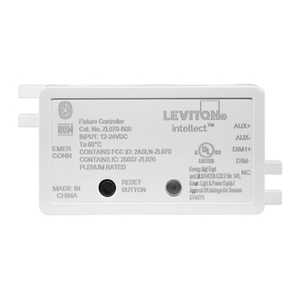
ZL070
Reset
Switch
LED Indicator
ZL0D0
Reset
Switch
LED Indicator
NOTE: Antenna applies to B0A and B2A models only.
Installation Requirements
• Installation and servicing should always be performed by qualified
personnel.
• Mounts within fixture wiring compartment.
• Dim-to-OFF LED driver with 12-24V AUX power supply and 0-10V or
DALI control.
Installation
WARNING: TO AVOID FIRE, SHOCK, OR DEATH: TURN OFF POWER
at circuit breaker or fuse and test that power is off before wiring!
1.
Secure the controller within the wiring compartment using the included
mounting screws.
2.
Remove 4 to 5 mm of insulation from each circuit conductor.
3.
Make sure ends of conductor are straight.
4.
Push conductor firmly into appropriate wire connector.
5.
controllers with external antenna (ZL070-B0A, B2A,
For
ZL0D0-B0A): The grommet on the end of the antenna wire is
designed for installation into a 2 mm diameter hole to provide stability
for the antenna wire outside the fixture. Locate a 2 mm hole as
needed on the fixture housing. Thread antenna wire through hole.
Push grommet into hole until secure.
6.
If installing with Emergency Sense Module (ZL027-0ES): Connect
the Emergency Sense Module to the Controller using the cable
included with the ZL027-0ES.
7.
Connect the Emergency Sense Module to Normal Power.
8.
Restore power at circuit breaker or fuse.
9.
Proceed to device enrollment per the included sheet and configuration
per your system requirements. Installation is complete.
Wireless Intelligent Fixture Controller
WC, 0-10V, DALI
Cat. Nos. ZL070-B00, B0A; ZL070-B20, B2A; ZL0D0-B00, B0A
INSTALLATION INSTRUCTIONS
• For indoor applications only. DO NOT use outdoors.
• DO NOT use this equipment for other than intended use.
• DO NOT mount near gas or electric heaters.
• Equipment should be mounted in locations and at heights where it will not
be subjected to tampering by unauthorized personnel.
• Use this device with COPPER OR COPPER CLAD WIRE ONLY.
SAVE THESE INSTRUCTIONS.
•
Emergency Wiring
When used for emergency lighting, the ZL027-0ES Emergency Sense
Module is required and shall be connected using the supplied cable.
The control input wires for the emergency light fixture are connected
to emergency power, and the Emergency Sense Module is connected
to normal power. Upon loss of normal power, the relay closes, and the
controller or sensor 0-10V lines go to high impedance allowing the load to
go to full output powered from the EM Source. Commands to change the
device output from full are ignored when the Emergency Sense Module is
in this mode. Upon restoration of normal power, the controller or sensor
will automatically resume normal operation.
Emergency Self-Test: NFPA 101 Life Safety Code and NEC (Article
700.3(B)) requires regular testing of all emergency equipment. To
perform a test of these products, a Test Switch that is a normally open,
momentary-break type, that returns the equipment to normal status when
released can be installed locally to interrupt normal power and perform
emergency system test.
*The diagram below depicts a "Momentary-Break Type Test Switch" ($)
on the normal power line to trigger the emergency systems test. Clarify
requirements with all local authorities.
EMERGENCY
FIXTURE
SENSOR
12 in. Cable
Controller or
MODULE
provided
Sensor
ZL027-0ES
with
Emergency
Sensor Module
Wiring Diagrams
ZL070-B00, B0A
Neutral
NL
(-) LED
Line
LN
(+) LED
1-Channel
(+) AUX
LED Driver
(-) AUX
With Auxiliary
Power Output
(+) DIM
(-) DIM
Earth
GND
ZL070-B20, B2A
Neutral
NL
(-) LED-2
Line
LN
(+) LED-2
(-) LED-1
(+) LED-1
2-Channel
LED Driver
(+) AUX
With Auxiliary
(-) AUX
Power Output
(+) DIM-1
(-) DIM-1
(-) CCT-2
(+) CCT-2
Earth
GND
ZL0D0-B00, B0A
Neutral
NL
Line
LN
DALI
LED Driver
Earth
GND
PK-A3378-10-00-2A-X3
AUX +
AUX -
VIOLET (DIM +)
GRAY (DIM -)
LIGHT FIXTURE
LINE
NEUTRAL
LINE
EMERGENCY
NEUTRAL
POWER
$*
LIGHTING CIRCUIT
LINE FEED
(NORMAL POWER)
AUX+
AUX-
DIM1+
DIM-
TO CH-2
LED Modules
TO CH-1
LED Modules
AUX+
AUX-
DIM1+
DIM-
DIM2+
(-) LED
(+) LED
(+) DALI
DALI+
(-) DALI
DALI-
ENGLISH
Advertisement
Table of Contents

Related Manuals for Leviton Intellect ZL070-B00


Summary of Contents for Leviton Intellect ZL070-B00
- Page 1 0-10V or DALI, depending on the model. The fixture to emergency power, and the Emergency Sense Module is connected controller interfaces with Leviton’s wireless systems using its built-in radio. to normal power. Upon loss of normal power, the relay closes, and the...
- Page 2 LIMITED 2 YEAR WARRANTY AND EXCLUSIONS Leviton warrants to the original consumer purchaser and not for the benefit of anyone else that this product at the time of its sale by Leviton is free of defects in materials and workmanship under normal and proper use for two years from the purchase date. Leviton’s only obligation is to correct such defects by repair or replacement, at its option.
Need help?
Do you have a question about the Intellect ZL070-B00 and is the answer not in the manual?
Questions and answers