Advertisement
Quick Links
WARNINGS AND CAUTIONS
• TO AVOID FIRE, SHOCK, OR DEATH; TURN OFF POWER at circuit breaker or fuse and test that power is off before wiring!
• To be installed and/or used in accordance with appropriate electrical codes and regulations.
• If you are unsure about any part of these instructions, consult an electrician.
• SAVE THESE INSTRUCTIONS.
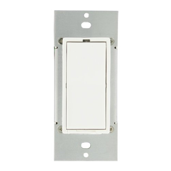
About Your Leviton UPB™ Wall Switch Dimmer
The Leviton UPB™ Wall Switch Dimmer (Figure 1) is a high quality light-switch/dimmer that not only allows for local rocker
switch control of a lighting load but also incorporates UPB™ two-way powerline communication technology that gives it the
ability to be remotely controlled by other UPB™ compatible controllers. The Leviton UPB™ Wall Switch is highly configurable
to allow for behaviors customized to each individual's desires. The Leviton UPB™ Wall Switch is capable of storing up to
16 preset light levels and fade rates to create powerful lighting scenes. The Leviton UPB™ Wall Switch is also capable of
transmitting UPB™ messages (including a current light level report) when rocker switch events occur. The Leviton UPB™
Wall Switch is capable of being set to a non-dimming mode in order to control such loads as fluorescent lights.
Figure 1 - 55A00-1 Leviton UPB™ Wall Switch Dimmer
BREAK-OFF TABS
LED
INDICATOR
BLACK
TOP
(ON/BRIGHT)
WHITE
RED
YELLOW
BOTTOM
(OFF/DIM)
GROUND
TO CASE
About Your 37A00-1 Leviton Auxiliary Switch
The 37A00-1 Leviton Auxiliary Switch (Figure 2) is a low cost (optional) companion device to the Leviton UPB™ Wall
Switch. The 37A00-1 has a rocker switch that controls the Leviton UPB™ Wall Switch in the same exact way that its local
rocker switch does.
Figure 2 – 37A00-1 Leviton Auxiliary Switch
LED
INDICATOR
BLACK
TOP
(ON/BRIGHT)
GRAY
BLUE
YELLOW
BOTTOM
(OFF/DIM)
LEVITON UPB™ 1000W WALL SWITCH DIMMER AND AUXILIARY SWITCH
55A00-1 (Leviton UPB™ 1000W Wall Switch Dimmer)
Installation Instructions
The Leviton UPB™ Wall Switch Dimmer is wired directly to the lighting circuit and can (optionally) be controlled by one or
more Leviton Auxiliary Switch producing three, four, or five-way circuits. Multi-way circuits make it possible for a group of
switches to control the same set of lights. This section will illustrate how to hook-up the connections.
NOTES:
1. Refer to Figures 1 and 2 to determine the wire colors of the hook-up.
2. All Leviton UPB™ Wall Switch Dimmers require a neutral (white) connection.
3. Leviton Auxiliary Switches require that the Line (black) wire be accessible. This wire may be connected to either phase
of the 120/240V supply.
4. The blue and/or gray wire on the Leviton Auxiliary Switch Dimmer can be connected to either earth ground or neutral.
The blue and/or gray wire serves only to light the LED on the Auxiliary Switch. This LED does not indicate anything
except that power is applied and to serve as a night-light.
LINE
37A00 (OPTIONAL)
AUXILIARY SWITCH
LINE
BLACK
NEUTRAL
LOAD
CONTROL WIRE FROM
AUXILIARY SWITCH
(wire must be capped off if not used)
NEUTRAL
*CONNECTING THE BLUE AND/OR GRAY WIRE TO NEUTRAL SETS THE COLOR OF THE LED INDICATOR.
CONNECT BLUE FOR BLUE INDICATOR, GRAY FOR RED INDICATOR, OR BOTH FOR MAGENTA INDICATOR.
BLUE AND/OR GRAY WIRE MAY BE CONNECTED TO NEUTRAL OR EARTH GROUND. NEUTRAL IS RECOMMENDED.
AIR-GAP SWITCH
The Leviton UPB™ Wall Switch rocker switch has an air-gap switch that will remove all power from the load for safe
installation and bulb replacement. To activate the air-gap switch firmly press the rocker bottom until you hear a loud "click"
or you see the SYSTEM "OFF" label on the top rocker.
Installation Procedure
1. Remove the faceplate from the existing wall switch.
2. Unscrew and pull the existing wall switch out of the wall box.
3. Disconnect the wires from the existing wall switch. Identify the "Line", "Neutral", "Load" and "Traveler" wires.
LINE
4. Install the 5 connecting wires per wiring configuration shown in Figure 3.
*NEUTRAL
NOTE: Be sure that the Leviton UPB™ Wall Switch is in the SYSTEM "OFF" position by firmly pressing the Rocker
(FOR RED INDICATOR)
Bottom until you click the air-gap switch to the open position or you see the SYSTEM "OFF" label on top of the Rocker.
*NEUTRAL
5. Optionally install any Leviton Auxiliary Switch per wiring configuration shown in Figure 3.
(FOR BLUE INDICATOR)
6. After all connections have been made, be certain that all wire connectors are firmly attached and there is no exposed
CONTROL WIRE FROM
copper.
LEVITON UPB™
7. Gently place the wires and Wall Switch into the wall box, with light emitting diode (LED) at the top of device, and screw
WALL SWITCH
in place.
8. Before installing the faceplate, restore power to the circuit, and firmly press the top of the Leviton UPB™ Wall Switch
Dimmer until it snaps out of the SYSTEM "OFF" position.
9. After testing the Leviton UPB™ Wall Switch Dimmer for proper local operation (per Table 2), install the faceplate
cover(s) to the outside of the Leviton UPB™ Wall Switch Dimmer(s).
37A00-1 (Leviton Auxiliary Switch)
INSTALLATION AND OPERATING INSTRUCTIONS
WARNINGS AND CAUTIONS
• To reduce the risk of overheating and possible damage to other equipment, do not use switch, when set to dimming-capable, to
control a receptacle, a motor-operated appliance, a fluorescent lighting fixture or a transformer-supplied appliance.
• Use this device with copper or copper-clad wire only.
• For indoor use only.
Figure 3 – Wiring Diagram
37A00 (OPTIONAL)
55A00
AUXILIARY SWITCH
Leviton Wall Switch
BLACK
BLACK
YELLOW
YELLOW
YELLOW
WHITE
*BLUE AND/OR GRAY
*BLUE AND/OR GRAY
COPPER
De-rating Information
For a proper fit in a multiple gang installation, it may be necessary to remove one or both sides (break-off tabs) from the
mounting plate (see Figure 1). When tabs are removed, the overall rating of the device must be reduced in accordance
with the following chart:
Table 1: 55A00-1 De-rating Information
Model
Device
No Fins
Maximum
Removed Deep
Load
Box
55A00-1
1000W
1000W
NOTE: When the 55A00-1 is mounted in a normal depth wall box it must also be de-rated from 1000W down to 900W.
Using Your Leviton UPB™ Wall Switch Dimmer
The Leviton UPB™ Wall Switch Dimmer is packed full of different options and configurations that can be programmed into it
using the UPB™ UPStart configuration software. This section will describe the operation of the Leviton UPB™ Wall Switch
Dimmer in its factory default configuration. Please refer to the section entitled "Configuring the Leviton UPB™ Wall Switch
Dimmer" for a description of the many other configuration options available.
Local Rocker Switch Operation
RED
The Leviton UPB™ Wall Switch Dimmer has a rocker switch that can be used to control the lighting load as described below
in Table 2.
Table 2: Rocker Switch Operation
Rocker Event
Top Rocker
Single-Tap
Brightens the light to 100% (on) at a
0.8-second fade rate.
Double-Tap
Snaps the light to 100% (on).
Hold
Starts fading (brightening) the light
towards 100% at a 3.3-second fade rate.
Release
Stops brightening the light.
LED Indicator
The Leviton UPB™ Wall Switch Dimmer comes equipped with a multi-color LED indicator that is normally lit to blue.
This LED indicator will blink different colors to indicate UPB™ communication status and configuration status as outlined
in Table 3 below.
Table 3: Status LED Operation
Leviton UPB™ Wall Switch Dimmer Status
The load connected to the Leviton UPB™ Wall Switch Dimmer is off
The load connected to the Leviton UPB™ Wall Switch Dimmer is on
Using Your Leviton Auxiliary Switch
The Leviton UPB™ Wall Switch can (optionally) be connected to one or more Leviton Auxiliary Switch producing three,
four, or five-way lighting circuits. Each Leviton Auxiliary Switch has a Decora
lighting load of the Leviton UPB™ Wall Switch in the same way as previously described in Table 2.
DI-02X-HL551-00A (55I00-1)
ENGLISH
No Fins Removed
One Fin Removed
Both Fins Removed
Normal Depth
Next to One
Next to Two
Box
Dimmer
Dimmers
900W
800W
600W
Bottom Rocker
Fades the light to 0% (off) at a 1.6-second
fade rate.
Snaps the light to 0% (off).
Starts fading (dimming) the light towards 0%
at a 3.3-second fade rate.
Stops dimming the light.
LED Color
Blue
Black
®
rocker switch that can be used to control the
Advertisement

Subscribe to Our Youtube Channel
Related Manuals for Leviton UPB 5A00-1


Summary of Contents for Leviton UPB 5A00-1
- Page 1 YELLOW WHITE CONTROL WIRE FROM BOTTOM The Leviton UPB™ Wall Switch Dimmer has a rocker switch that can be used to control the lighting load as described below AUXILIARY SWITCH (OFF/DIM) in Table 2. (wire must be capped off if not used)
- Page 2 For warranty information and/or product returns, residents of Canada should contact Leviton in writing at Leviton Manufacturing of Canada Ltd to the attention of the Quality Assurance Department, 165 Hymus Blvd, Pointe-Claire (Quebec), Canada H9R 1E9 or by telephone at 1 800 405-5320.
Need help?
Do you have a question about the UPB 5A00-1 and is the answer not in the manual?
Questions and answers