
Related Manuals for Leviton smartlockpro GFNT1


Summary of Contents for Leviton smartlockpro GFNT1
- Page 1 Installing and Testing a GFCI Receptacle Please read this leaflet completely before getting started. Avoid miswiring the GFCI. See video link for help on wiring. PK-93792-10-00-2H - Mobile Test - X0 AR 1723...
- Page 2 CAUTION • To prevent severe shock or electrocution always turn the power OFF at the service panel before working with wiring. • Use this GFCI with copper or copper-clad wire. Do not use it with aluminum wire. • Do not install this GFCI receptacle on a circuit that powers life support equipment because if the GFCI trips it will shut down the equipment.
- Page 3 1. What is a GFCI? A GFCI receptacle is different from conventional receptacles. In the event of a ground fault, a GFCI will trip and quickly stop the flow of electricity to prevent serious injury. Definition of a ground fault: Instead of following its normal safe path, electricity passes through a person's body to reach the ground.
-
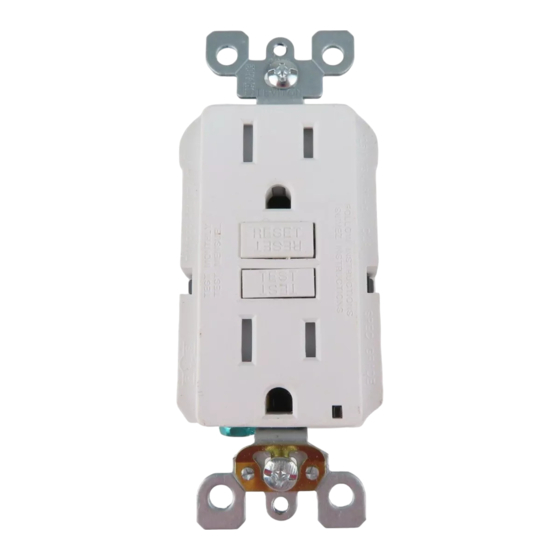
Page 4: Front View
2. The GFCI's features FRONT VIEW Receptacle Outlet RESET button: See step 8 RESET TEST button: TEST See step 8 Outlet Self-Ground Clip Mounting Bracket Green/Red Status Indicator Light... - Page 5 BACK VIEW Screw (terminal) colors: LINE Green = grounding terminal Hot terminal (Brass or Black): Silver = WHITE terminals Connection for the LINE Brass or Black = HOT terminals cable's black wire LINE A yellow sticker White terminal (Silver): covers the LOAD Connection for the LINE ca- terminals.
- Page 6 3. Should you install it? Installing a GFCI receptacle can be more complicated than installing a conventional receptacle. Make sure that you: • Understand basic wiring principles and techniques • Can interpret wiring diagrams • Have circuit wiring experience • Are prepared to take a few minutes to test your work, making sure that you have wired the GFCI receptacle correctly...
-
Page 7: Load Cable
4. LINE vs. LOAD A cable consists of 2 or 3 wires. Cable Wires LINE cable: Delivers power from the service panel (breaker panel or fuse box) to the GFCI. If there is only one cable entering the electrical box, it is the LINE cable. -
Page 8: Turn The Power Off
5. Turn the power OFF Plug an electrical device, such as a lamp or radio, into the receptacle on which you are working. Turn the lamp or radio ON. Then, go to the service panel. Find the breaker or fuse that protects that receptacle. - Page 9 6. Identify cables/wires Important: DO NOT install the GFCI receptacle in an electrical box containing (a) more than four (4) wires (not including the grounding wires) or (b) cables with more than two (2) wires (not including the grounding wire). Contact a qualified electrician if either (a) or (b) are true.
- Page 10 Procedure: box with two (2) cables (4-6 wires): (a) Detach one cable's white wire and hot wires from the receptacle and cap each one separately with a wire connector. Make sure that they are from the same cable. (b) Re-install the receptacle in the electrical box, attach faceplate, then turn the power ON at the service panel.
- Page 11 Placement in circuit: The GFCI's place in the circuit determines if it protects other receptacles in the circuit. Sample circuit: LINE LINE LINE Service Panel LOAD LOAD Placing the GFCI in position A will also provide protection to "load side" receptacles B and C.
- Page 12 ONLY. Tighten screws to 14-18 in-lbs. Torque values LOAD CHARGE can also be found at Leviton.com/torquevalue. Torque values can also be found at Leviton.com/torquevalue. Connect the LINE cable wires to the LINE terminals: • The white wire connects to the WHITE terminal (Silver) •...
- Page 13 Tighten screws to LOAD CHARGE 14-18 in-lbs. Torque values can also be found at Leviton.com/torquevalue. Torque values can also be found at Leviton.com/torquevalue. Connect the LINE cable wires to the LINE terminals: • The white wire connects to the WHITE terminal (Silver) •...
- Page 14 FOR CANADA ONLY For warranty information and/or product returns, residents of Canada should contact Leviton in writing at Leviton Manufacturing of Canada ULC to the attention of the Quality Assurance Department, 165 Hymus Blvd, Pointe-Claire (Quebec), Canada H9R 1E9 or by telephone at 1 800 405-5320.
Need help?
Do you have a question about the smartlockpro GFNT1 and is the answer not in the manual?
Questions and answers