Leviton smartlockpro GFCI Manual
- Leaflet (2 pages) ,
- Instruction sheet (3 pages)
Advertisement
What is a GFCI?
A GFCI receptacle is different from conventional receptacles. In the event of a ground fault, a GFCI will trip and quickly stop the flow of electricity to prevent serious injury.
Definition of a ground fault:
Instead of following its normal safe path, electricity passes through a person's body to reach the ground. For example, a defective appliance can cause a ground fault.
A GFCI receptacle does NOT protect against circuit overloads, short circuits, or shocks. For example, you can still be shocked if you touch bare wires while standing on a non-conducting surface, such as a wood floor.
NOTE:
GFCI's contain a lockout feature that will prevent RESET if:
- There is no power being supplied to the GFCI.
- The GFCI is miswired due to reversal of the LINE and LOAD leads.
- The GFCI cannot pass its internal test, indicating that it may not be able to provide protection in the event of a ground fault.
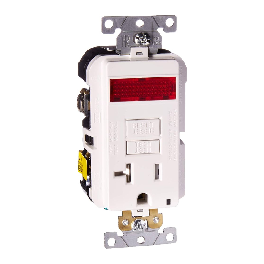
THE GFCI FEATURE
FRONT VIEW

BACK VIEW

* Back wire LINE terminals have a captive clamp feature to ease insertion of wires for first time wiring only.
Should you install it?
Installing a GFCI receptacle can be more complicated than installing a conventional receptacle.
Make sure that you:
- Understand basic wiring principles and techniques
- Can interpret wiring diagrams
- Have circuit wiring experience
- Are prepared to take a few minutes to test your work, making sure that you have wired the GFCI receptacle correctly
LINE vs. LOAD
A cable consists of 2 or 3 wires.

LINE cable:
Delivers power from the service panel (breaker panel or fuse box) to the GFCI. If there is only one cable entering the electrical box, it is the LINE cable. This cable should be connected to the GFCI's LINE terminals only.
LOAD cable:
Delivers power from the GFCI to another receptacle in the circuit. This cable should be connected to the GFCI's LOAD terminals only. The LOAD terminals are under the yellow sticker. Do NOT remove the sticker at this time.
Turn the power OFF
Plug an electrical device, such as a lamp or radio, into the receptacle on which you are working. Turn the lamp or radio ON. Then, go to the service panel. Find the breaker or fuse that protects that receptacle. Place the breaker in the OFF position or completely remove the fuse. The lamp or radio must turn OFF.

Next, plug in and turn ON the lamp or radio at the receptacle's other outlet to make sure the power is OFF at both outlets. If the power is not OFF, stop work and call an electrician to complete the installation.
Identify cables/wires

DO NOT install the GFCI receptacle in an electrical box containing (a) more than four (4) wires (not including the grounding wires) or (b) cables with more than two (2) wires (not including the grounding wire). Contact a qualified electrician if either (a) or (b) are true.
If you are replacing an old receptacle, pull it out of the electrical box without disconnecting the wires.
- If you see one cable (2-3 wires), it is the LINE cable. The receptacle is probably in position C (see diagram to the right). Remove the receptacle and go to step 7A.
- If you see two cables (4-6 wires), the receptacle is probably in position A or B (see diagram to the right). Follow steps a-e of the procedure to the right.
Procedure: box with two (2) cables (4-6 wires):
- Detach one cable's white wire and hot wires from the receptacle and cap each one separately with a wire connector. Make sure that they are from the same cable.
- Re-install the receptacle in the electrical box, attach faceplate, then turn the power ON at the service panel.
- Determine if power is flowing to the receptacle. If so, the capped wires are the LOAD wires. If not, the capped wires are the LINE wires.
- Turn the power OFF at the service panel, label the LINE and LOAD wires, then remove the receptacle.
- Go to step 7B.
Placement in circuit:
The GFCI's place in the circuit determines if it protects other receptacles in the circuit.
Sample circuit:

Placing the GFCI in position A will also provide protection to "load side" receptacles B and C. On the other hand, placing the GFCI in position C will not provide protection to receptacles A or B. Remember that receptacles A, B, and C can be in different rooms.
Connect the wires (choose A or B)... only after reading other side completely
- One Cable (2 or 3 wires) entering the box
 entering the box")
About Wire Connections:
Side Wire:
![]()
Back Wire:
![]()
 entering the box")


NOTE: LINE and LOAD wiring terminals accept #10 - #14 AWG solid or stranded copper wire.
Connect the LINE cable wires to the LINE terminals:
- The white wire connects to the WHITE terminal (Silver)
- The black wire connects to the HOT terminal (Brass or Black)
Connect the grounding wire (only if there is a grounding wire):
- For a box with no grounding terminal (diagram not shown): Connect the LINE cable's bare copper (or GREEN) wire directly to the grounding terminal on the GFCI receptacle.
- For a box with a grounding terminal (diagram shown above): Connect a 6-inch bare copper (or GREEN) 10 - 14 AWG wire to the grounding terminal on the GFCI. Also connect a similar wire to the grounding terminal on the box. Connect the ends of these wires to the LINE cable's bare copper (or GREEN) wire using a wire connector. If these wires are already in place, check the connections.
Complete the installation:
- Fold the wires into the box, keeping the grounding wire away from the WHITE and HOT terminals. Screw the receptacle to the box and attach the faceplate.
- Go to step 8.
OR
- Two cables (4 or 6 wires) entering the box
 entering the box")
About Wire Connections:
Side Wire:
![]()
Back Wire:
![]()
 entering the box")

NOTE: LINE and LOAD wiring terminals accept #10 - #14 AWG solid or stranded copper wire.
Connect the LINE cable wires to the LINE terminals:
- The white wire connects to the WHITE terminal (Silver)
- The black wire connects to the HOT terminal (Brass or Black)
Connect the LOAD cable wires to the LOAD terminals:
- Remove the YELLOW sticker to reveal the LOAD terminals
- The white wire connects to the WHITE terminal (Silver)
- The black wire connects to the HOT terminal (Brass or Black)
Connect the grounding wires (only if there is a grounding wire):
- Connect a 6-inch bare copper (or GREEN) 12 or 14 AWG wire to the grounding terminal on the GFCI. If the box has a grounding terminal, also connect a similar wire to the grounding terminal on the box. Connect the ends of these wires to the LINE or LOAD cable's bare copper (or GREEN) wire using a wire connector. If these wires are already in place, check the connections.
Complete the installation:
- Fold the wires into the box, keeping the grounding wire away from the WHITE and HOT terminals. Screw the receptacle to the box and attach the faceplate.
- Go to step 8.
Test your work
Why perform this test?
- If you miswired the GFCI it may not prevent personal injury or death due to a ground fault (electrical shock).
- If you mistakenly connect the LINE wires to the LOAD terminals, the GFCI will not reset and will not provide power to either the GFCI receptacle face or any receptacles fed from the GFCI.
Procedure:

- This GFCI is shipped from the factory in the tripped condition and cannot be reset until it is wired correctly and power is supplied to the device. Plug a lamp or radio into the GFCI (and leave it plugged in). Turn the power ON at the service panel. Ensure that the GFCI is still in the tripped condition by pressing the TEST button. If the indicator light on the GFCI receptacle face is ON and the lamp or radio is OFF go to the Troubleshooting section because LINE and LOAD wiring connections have been reversed. You will not be able to RESET the GFCI in this condition.
- Press the RESET button fully. If the lamp or radio turns ON and the Indicator Light turns ON, the GFCI has been installed correctly. If the GFCI cannot be reset, go to the Troubleshooting section.
- If you installed your GFCI using step 7B press the TEST button, then plug a lamp or radio into surrounding receptacles to see which one(s), in addition to the GFCI, lost power when you pressed the TEST button. DO NOT plug life saving devices into any of the receptacles that lost power. Place a "GFCI PROTECTED OUTLET" sticker on every receptacle that lost power, then press the RESET button to reset the GFCI.
- Press the TEST button (then RESET button) every month to assure proper operation. If the Indicator light does not go out and come back on or if the GFCI cannot be reset, then it must be replaced.
TROUBLESHOOTING
Turn the power OFF and check the wire connections against the appropriate wiring diagram in step 7A or 7B. Make sure that there are no loose wires or loose connections. Start the test from the beginning of step 8 if you rewired any connections to the GFCI.
General Information
| Cat. No. | Description | Features |
| X7591-PL | 15A-125V AC, 60 Hz Tamper Resistant SmartlockPro Slim GFCI w/Pilot Light | LED Pilot Light turns ON when GFCI is RESET. NOTE: Tripping GFCI turns LED Pilot Light OFF. Power to GFCI and any downstream receptacles fed from load terminals of GFCI will not be available until GFCI is RESET. |
| X7891-PL | 20A-125V AC, 60 Hz Tamper Resistant SmartlockPro Slim GFCI w/Pilot Light | |
| All devices rated 20A feed-through |

- To prevent severe shock or electrocution always turn the power OFF at the service panel before working with wiring.
- Use this GFCI with copper or copper-clad wire. Do not use it with aluminum wire.
- Do not install this GFCI receptacle on a circuit that powers life support equipment because if the GFCI trips it will shut down the equipment.
- For installation in wet locations, protect the GFCI receptacle with a weatherproof cover that will keep both the receptacle and any plugs dry.
- Must be installed in accordance with national and local electrical codes.
Documents / ResourcesDownload manual
Here you can download full pdf version of manual, it may contain additional safety instructions, warranty information, FCC rules, etc.
Advertisement


Need help?
Do you have a question about the smartlockpro GFCI and is the answer not in the manual?
Questions and answers