MacDon FlexDraper FD75 Operator's Manual
Flex-float
Hide thumbs
Also See for FlexDraper FD75:
- Operator's manual (552 pages) ,
- Unloading and assembly instructions (68 pages) ,
- Manual (29 pages)

Related Manuals for MacDon FlexDraper FD75


Summary of Contents for MacDon FlexDraper FD75
- Page 1 FD75 ® FlexDraper Combine Header Operator’s Manual 214323 Revision B Original Instruction Featuring MacDon FLEX-FLOAT Technology™ The Harvesting Specialists.
- Page 2 © 2022 MacDon Industries, Ltd. The information in this publication is based on the information available and in effect at the time of printing. MacDon Industries, Ltd. makes no representation or warranty of any kind, whether expressed or implied, with respect to the...
- Page 3 MacDon provides warranty for Customers who operate and maintain their equipment as described in this manual. A copy of the MacDon Industries Limited Warranty Policy, which explains this warranty, should have been provided to you by your Dealer. Damage resulting from any of the following conditions will void the warranty: •...
- Page 4 • Russian • Spanish Translated manuals can be downloaded from the Dealer Portal (https://portal.macdon.com). The following conventions are used in this document: • Right and left are determined from the operator’s position. The front of the header is the side that faces the crop; the back of the header is the side that connects to the combine.
- Page 5 Summary of Changes At MacDon, we’re continuously making improvements, and occasionally these improvements affect product documentation. The following list provides an account of major changes from the previous version of this document. Internal Use Summary of Change Only Section Added “hoodies” to the list of dangling items that you should never 1.3 General Safety, page 3...
- Page 6 Internal Use Summary of Change Only Section Deleted the empty title topic “Lubricating Header Drive Gearbox” Technical — and promoted the procedures under it. Publications ECN 61432 6.4.4 Changing Oil Filter, page Updated filter number MD #183620 to kit MD #320360. Topic heading “Cutterbar”...
- Page 7 Model and Serial Number Record the model number, serial number, and model year of the header, combine adapter, and transport/stabilizer wheel option (if installed) in the spaces provided. NOTE: Right and left designations are determined from the operator’s position, facing forward. Draper Header Header Model: Serial Number:...
-
Page 9: Table Of Contents
TABLE OF CONTENTS Introduction ..............................i Summary of Changes........................... iii Model and Serial Number ..........................v Chapter 1: Safety ............................1 1.1 Safety Alert Symbols ..........................1 1.2 Signal Words ............................2 1.3 General Safety ............................3 1.4 Maintenance Safety ..........................5 1.5 Hydraulic Safety .............................7 1.6 Safety Signs ............................8 1.6.1 Installing Safety Decals........................8 1.7 Safety Decal Locations..........................9... - Page 10 TABLE OF CONTENTS 3.6.2 Header Settings ........................... 43 3.6.3 Optimizing Header for Straight Combining Canola................49 Checking and Adjusting Feed Auger Springs..................49 3.6.4 Reel Settings ..........................50 3.7 Header Operating Variables........................54 3.7.1 Cutting Height ..........................54 Cutting off Ground ........................54 Cutting on Ground ........................
- Page 11 TABLE OF CONTENTS 3.11.2 Installing Beater Bars ........................ 112 3.12 Transporting Header ......................... 113 3.12.1 Transporting Header on Combine....................113 3.12.2 Towing Header ........................113 Attaching Header to Towing Vehicle .................... 114 Precautions for Towing a Header....................114 3.12.3 Converting from Transport to Field Position .................. 115 Removing Tow-Bar........................
- Page 12 TABLE OF CONTENTS 4.8.3 Calibrating Auto Header Height Control – Challenger ® 6 Series ............165 4.8.4 Adjusting Header Height – Challenger ® 6 Series ................167 4.8.5 Adjusting Header Raise/Lower Rate – Challenger ® 6 Series ..............168 4.8.6 Setting Sensitivity of Auto Header Height Control – Challenger ®...
- Page 13 TABLE OF CONTENTS 4.15.1 Checking Voltage Range from Combine Cab – John Deere 60 Series ..........226 4.15.2 Calibrating Auto Header Height Control – John Deere 60 Series............228 4.15.3 Turning Off Accumulator – John Deere 60 Series................230 4.15.4 Setting Sensing Grain Header Height – John Deere 60 Series............230 4.15.5 Setting Sensitivity of Auto Header Height Control –...
- Page 14 TABLE OF CONTENTS 5.1.1 Using Flighting Extensions ......................289 5.1.2 Using Stripper Bars........................289 5.1.3 Adjusting Auger Speed ........................ 289 5.2 Case IH Combines ..........................290 5.2.1 Attaching Header to Case IH Combine ................... 290 5.2.2 Detaching Header from Case IH Combine ..................294 5.3 Challenger ®...
- Page 15 TABLE OF CONTENTS 6.4.3 Changing Oil in Hydraulic Reservoir ....................368 6.4.4 Changing Oil Filter........................369 6.5 Electrical System ..........................371 6.5.1 Replacing Light Bulbs ........................371 6.6 Header Drive ............................. 372 6.6.1 Removing Driveline ........................372 6.6.2 Installing Driveline........................372 6.6.3 Removing Driveline Guard ......................
- Page 16 TABLE OF CONTENTS 6.10 Adapter Feed Draper ......................... 428 6.10.1 Replacing Adapter Feed Draper ....................428 6.10.2 Checking and Adjusting Feed Draper Tension ................429 6.10.3 Adapter Drive Roller ......................... 430 Removing Adapter Feed Draper Drive Roller.................. 430 Installing Adapter Feed Draper Drive Roller ................... 432 Replacing Adapter Feed Draper Drive Roller Bearing ...............
- Page 17 TABLE OF CONTENTS Replacing Reel Endshield Supports....................487 6.14 Reel Drive............................488 6.14.1 Replacing Reel Drive Cover ......................488 Removing Reel Drive Cover ......................488 Installing Reel Drive Cover......................489 6.14.2 Adjusting Reel Drive Chain Tension....................489 Loosening Reel Drive Chain ......................489 Tightening Reel Drive Chain ......................
- Page 18 TABLE OF CONTENTS 7.4.3 Stabilizer / Slow Speed Transport Wheels..................514 7.5 Crop Delivery ............................. 515 7.5.1 Auger Dent Repair Kit ......................... 515 7.5.2 CA25 Combine Adapter Feed Auger Flighting .................. 515 7.5.3 Draper Deflector – Narrow ......................516 7.5.4 Draper Deflector – Wide ......................516 7.5.5 Draper Clips ..........................
-
Page 19: Chapter 1: Safety
Chapter 1: Safety Understanding and consistently following these safety procedures will help to ensure the safety of those operating the machine and of bystanders. 1.1 Safety Alert Symbols The safety alert symbol indicates important safety messages in this manual and on safety signs on the machine. This symbol means: •... -
Page 20: Signal Words
SAFETY 1.2 Signal Words Three signal words, DANGER, WARNING, and CAUTION, are used to alert you to hazardous situations. Two signal words, IMPORTANT and NOTE, identify non-safety related information. Signal words are selected using the following guidelines: DANGER Indicates an imminently hazardous situation that, if it is not prevented, will result in death or serious injury. WARNING Indicates a potentially hazardous situation that, if it is not prevented, could result in death or serious injury. -
Page 21: General Safety
SAFETY 1.3 General Safety Operating, servicing, and assembling machinery presents several safety risks. These risks can be reduced or eliminated by following the relevant safety procedures and wearing the appropriate personal protective equipment. CAUTION The following general farm safety precautions should be part of your operating procedure for all types of machinery. - Page 22 SAFETY • Wear close-fitting clothing and cover long hair. NEVER wear dangling items such as hoodies, scarves or bracelets. • Keep all shields in place. NEVER alter or remove safety equipment. Ensure that the driveline guards can rotate independently of their shaft, and that they can telescope freely.
-
Page 23: Maintenance Safety
SAFETY 1.4 Maintenance Safety Maintaining your equipment safely requires that you follow the relevant safety procedures and wear the appropriate personal protective equipment for the task. To ensure your safety while maintaining the machine: • Review the operator’s manual and all safety items before operating or performing maintenance on the machine. - Page 24 SAFETY • Wear protective gear when working on the machine. • Wear heavy gloves when working on knife components. Figure 1.10: Personal Protective Equipment 214323 Revision B...
-
Page 25: Hydraulic Safety
SAFETY 1.5 Hydraulic Safety Because hydraulic fluid is under extreme pressure, hydraulic fluid leaks can be very dangerous. The proper safety procedures must be followed when inspecting for hydraulic fluid leaks and servicing hydraulic equipment. • Always place all hydraulic controls in Neutral before leaving the operator’s seat. -
Page 26: Safety Signs
• If the original part on which a safety sign was installed is replaced, ensure that the repair part displays the current safety sign. • Replacement safety signs are available from your MacDon Dealer. Figure 1.14: Operator’s Manual Decal 1.6.1 Installing Safety Decals Worn or damaged safety decals will need to be removed and replaced. -
Page 27: Safety Decal Locations
SAFETY 1.7 Safety Decal Locations Safety decals are installed in several locations on the header. Replace any missing or damaged decals on the machine with identical parts. Figure 1.15: Upper Cross Auger A - MD #174682 Figure 1.16: Slow Speed Transport A - MD #220799 214323 Revision B... - Page 28 SAFETY Figure 1.17: Slow Speed Transport Tow-Bar A - MD #220797 B - MD #220798 Figure 1.18: Vertical Knife A - MD #174684 214323 Revision B...
- Page 29 SAFETY Figure 1.19: Endsheets, Reel Arms, Backsheet A - MD #131393 (2 Places) B - MD #174632 (2 Places) C - MD #184422 (Single Knife – Left Side Only; Double Knife – Both Sides) D - MD #184422 (Single Knife – Left Side Only; Double Knife – Both Sides) E - MD #131392 (Double Reel 2 Places) F - MD #131391 (2 Places) H - MD #131393 (Single Reel –...
- Page 30 SAFETY Figure 1.20: Backtube A - MD #184372 B - MD #166466 C - MD #131391 D - MD #131392 E - MD #184372 (Split Frame) 214323 Revision B...
-
Page 31: Understanding Safety Signs
SAFETY 1.8 Understanding Safety Signs Safety sign decals use illustrations to convey important safety or equipment maintenance information. MD #113482 General hazard pertaining to machine operation and servicing DANGER To prevent injury or death from improper or unsafe machine operation: •... - Page 32 SAFETY MD #131392 Reel crushing hazard WARNING To prevent injury from the fall of a raised reel: fully raise the reel, stop the engine, remove the key from the ignition, and engage the safety prop on each reel support arm before working on or under the reel.
- Page 33 SAFETY MD #174436 High-pressure oil hazard WARNING High-pressure hydraulic fluid can penetrate human skin, which can cause serious injury such as gangrene, which can be fatal. To prevent this: • Do NOT go near hydraulic fluid leaks. • Do NOT use a finger or skin to check for hydraulic fluid leaks.
- Page 34 SAFETY MD #174684 Knife cutting hazard WARNING To prevent injury from a sharp cutting knife: • Wear heavy canvas or leather gloves when working with the knife. • Be sure no one is near the vertical knife when removing or rotating the knife.
- Page 35 SAFETY MD #184372 General hazard pertaining to machine operation and servicing DANGER To prevent injury or death from the improper or unsafe operation of the machine: • Read the operator’s manual and follow all safety instructions. If you do not have a manual, obtain one from your Dealer.
- Page 36 SAFETY MD #190546 Slipping hazard WARNING To prevent injury or death: • Do NOT use this area as a step or platform. Figure 1.34: MD #190546 MD #193147 Loss of control hazard DANGER To prevent injury or death from loss of control: •...
- Page 37 SAFETY MD #194521 Auger entanglement hazard DANGER To prevent injury from entanglement with rotating auger: • Stand clear of header while machine is running. • Do NOT operate without shields in place. • Stop engine and remove key before opening shield. General hazard pertaining to machine operation and servicing.
- Page 38 SAFETY MD #220798 Loss of control hazard DANGER To prevent serious injury or death from loss of control: • Do NOT tow the header with a damaged tow bar. • Consult the operator’s manual for more information. Figure 1.38: MD #220798 MD #220799 Loss of control hazard WARNING...
-
Page 39: Chapter 2: Product Overview
Chapter 2: Product Overview The product overview provides the dimensions, details, and performance criteria for the various sizes and configurations. 2.1 Definitions The following terms, abbreviations, and acronyms are used in this manual. Term Definition American Petroleum Institute American Society of Testing and Materials ASTM A headed and externally threaded fastener designed to be paired with a nut Bolt... - Page 40 PRODUCT OVERVIEW Term Definition Turns from finger tight TFFT The product of a force * the length of a lever arm, usually measured in Newton-meters Torque (Nm) or foot-pounds (lbf∙ft) A tightening procedure in which a fitting is assembled to a specified tightness (usually Torque angle finger tight) and then the nut is turned farther by a specified number of degrees until it achieves its final position...
-
Page 41: Specifications
PRODUCT OVERVIEW 2.2 Specifications Specifications and design are subject to change without notice or obligation to revise previously sold units. The following symbol and letters are used in Table 2.1, page 23 and Table 2.2, page | FD75 | CA25 | Attachments : optional (dealer installed) / —: not available S: standard / O : optional (factory installed) / O... - Page 42 PRODUCT OVERVIEW Table 2.1 Header Specifications (continued) Conveyor (Draper) and Decks Draper width 1057 mm (41.61 in.) Draper drive Hydraulic Draper speed: CA25 Combine Adapter-controlled 141 m/min. (0–464 fpm) Delivery opening width 1870 mm (73.62 in.) PR15 Pick-Up Reel 5-, 6-, or 9 Quantity of tine tubes Center tube diameter 203 mm (8 in.)
- Page 43 PRODUCT OVERVIEW Figure 2.1: Header Width 214323 Revision B...
- Page 44 PRODUCT OVERVIEW Table 2.2 Header Attachments CA25 Combine Adapter Feed draper 2000 mm (78.7 in.) Width 107–122 m/min Feed draper Speed (350–400 fpm) Feed auger 1660 mm (65.3 in.) Width Feed auger 559 mm (22 in.) Outside diameter Feed auger 356 mm (14 in.) Tube diameter Speed (varies with...
-
Page 45: Component Identification
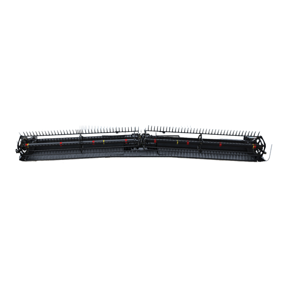
PRODUCT OVERVIEW 2.3 Component Identification This section will help you to identify common component names that are used throughout this manual. ® 2.3.1 FD75 FlexDraper ® Figure 2.2: FD75 FlexDraper Components A - Wing Float Linkage B - Center-Link C - Center Reel Arm Prop Handle D - Transition Pan E - Reel Fore-Aft Cylinder F - Reel Lift Cylinder... -
Page 46: Ca25 Combine Adapter
PRODUCT OVERVIEW 2.3.2 CA25 Combine Adapter Figure 2.3: Header Side of CA25 Combine Adapter A - Feed Auger B - Header Float Springs C - Center-Link D - Hydraulic Reservoir E - Gearbox F - Header Support Arm G - Feed Draper Figure 2.4: Combine Side of CA25 Combine Adapter A - Adapter Gearbox B - Hydraulic Compartment Cover... -
Page 47: Chapter 3: Operation
• It is your responsibility to read and understand this manual completely before operating the header. Contact your MacDon Dealer if an instruction is not clear to you. • Follow all safety messages in the manual and on safety decals on the machine. -
Page 48: Operational Safety
OPERATION 3.2 Operational Safety Follow all the safety and operational instructions given in this manual. CAUTION Adhere to the following safety precautions: • Follow all safety and operational instructions provided in your operator’s manuals. If you do not have a combine manual, get one from your Dealer and read it thoroughly. -
Page 49: Reel Safety Props
OPERATION 3.2.2 Reel Safety Props The reel safety props are located on the reel arms. When engaged, the reel safety props prevent the reel from falling unexpectedly. IMPORTANT: To prevent damage to the reel support arms, do NOT transport the header with the reel safety props engaged. Engaging Reel Safety Props Engage the reel safety props whenever you intend to work on or around a raised reel. -
Page 50: Disengaging Reel Safety Props
OPERATION 5. Double-reel header, center arm: Use handle (A) to move the lock rod to inboard position (B), which engages pin (C) under the prop. 6. Double-reel header, center arm: Lower the reel until the safety props contact the outer arm cylinder mounts and the center arm pin. -
Page 51: Endshields
OPERATION 5. Double-reel headers, center reel arm: Use handle (B) to move lock rod (A) to the outboard position. Figure 3.6: Reel Safety Prop – Center Arm 3.2.3 Endshields A hinged, polyethylene endshield is fitted on each end of the header. Opening Endshield The header endshields cover components. -
Page 52: Closing Endshield
OPERATION IMPORTANT: Do NOT force the endshield once it has reached its end of travel or damage to the endshield structure may result. The endshield is designed to open sufficiently to allow access to the drive system and manual case. NOTE: If complete access to endsheet area is required, remove the endshield. -
Page 53: Removing Endshield
OPERATION 5. Replace tool (B) and lynch pin (A) on top pin (C). Figure 3.12: Left Endshield Pin Removing Endshield It may be necessary to remove the endshield to perform certain servicing tasks. 1. Open the endshield. For instructions, refer to Opening Endshield, page 2. -
Page 54: Installing Endshield
OPERATION Installing Endshield If an endshield has been removed, it will need to be reinstalled before the header can be safely operated. 1. Place the endshield onto support (A), and align the hole in the endshield with stud (B) on the support. Figure 3.14: Left Endshield 2. -
Page 55: Adjusting Endshield
OPERATION Adjusting Endshield Polyethylene endshields expand or contract when subjected to large temperature changes. The position of the top pin and the lower catch can be adjusted to compensate for dimensional changes. 1. Measure gap (X) between the front end of the endshield and the header frame and compare the measurement to the values provided in Table 3.1, page... -
Page 56: Linkage Covers
OPERATION 3.2.4 Linkage Covers Plastic covers are attached to the header frame to protect the header wing balance mechanism from debris and weather. Removing Linkage Covers 1. Remove screw (A) and lift outboard end of cover (B). Figure 3.18: Linkage Cover 2. -
Page 57: Daily Start-Up Check
OPERATION 3. Install screw (A) to hold cover (B) in place. Figure 3.21: Linkage Cover 3.2.5 Daily Start-Up Check Complete the following tasks each day before starting the machine. CAUTION • Clear the area of other persons, pets, etc. Keep children away from machinery. -
Page 58: Break-In Period
OPERATION 3.3 Break-in Period Until you become familiar with the sound and feel of your new header, be extra attentive. CAUTION Before investigating an unusual sound or attempting to correct a problem, shut off engine and remove key. After attaching the header to the combine for the first time, follow these steps: 1. -
Page 59: Shutting Down Header
OPERATION 3.4 Shutting down Header To prevent injuries and equipment damage, always perform the procedures for shutting down the header. DANGER To prevent bodily injury or death from the unexpected start-up of the machine, always stop the engine and remove the key from the ignition before leaving the operator’s seat for any reason. -
Page 60: Cab Controls
OPERATION 3.5 Cab Controls The primary header functions are controlled inside the combine cab. CAUTION Be sure all bystanders are clear of machine before starting engine or engaging any header drives. Refer to your combine operator’s manual to identify the following in-cab controls: •... -
Page 61: Header Setup
3.6.1 Header Attachments Several attachments to optimize the performance of your FD75 FlexDraper ® Header are available as options from your MacDon Dealer. Refer to 7 Options and Attachments, page 507 for descriptions of available kits. 3.6.2 Header Settings Table 3.2, page 44... - Page 62 OPERATION 214323 Revision B...
- Page 63 OPERATION 214323 Revision B...
- Page 64 OPERATION 214323 Revision B...
- Page 65 OPERATION 214323 Revision B...
- Page 66 OPERATION 214323 Revision B...
-
Page 67: Optimizing Header For Straight Combining Canola
OPERATION 3.6.3 Optimizing Header for Straight Combining Canola Ripe canola can be straight cut, but most varieties are susceptible to shelling and seed loss. The recommended settings and attachments to optimize FD75 FlexDraper ® Headers for straight cutting canola are provided. For recommended attachments, refer to 7 Options and Attachments, page 507 The optimization process includes the following modifications to the header:... -
Page 68: Reel Settings
OPERATION 4. At the left back corner of the header, check the thread length protruding past nut (A). The length should be 15 mm (0.60 in.). If the protruding thread length is not correct, proceed to Step 5, page Figure 3.23: Spring Tensioner 5. - Page 69 OPERATION Table 3.4 Illustrated Reel Settings Cam Setting Number Reel Position Reel Finger Pattern (Finger Speed Gain) Number 1 (0) 6 or 7 2 (20%) 6 or 7 214323 Revision B...
- Page 70 OPERATION Table 3.4 Illustrated Reel Settings (continued) Cam Setting Number Reel Position Reel Finger Pattern (Finger Speed Gain) Number 3 (30%) 3 or 4 4 (35%) 2 or 3 The following points describe the expected results for certain reel position adjustments: •...
- Page 71 OPERATION For more information, refer to Table 3.4, page 214323 Revision B...
-
Page 72: Header Operating Variables
OPERATION 3.7 Header Operating Variables Satisfactory header function requires making adjustments to suit various crops and conditions, reduce crop loss, and increases productivity. The variables listed in Table 3.5, page 54 allow the operator to affect the header performance. You will quickly become adept at adjusting the machine to achieve the results you desire. Most of the adjustments have been preset at the factory, but the settings can be changed to suit crop conditions. - Page 73 OPERATION DANGER To prevent bodily injury or death from the unexpected start-up of the machine, always stop the engine and remove the key from the ignition before leaving the operator’s seat for any reason. 1. Raise the header so the stabilizer wheels are off the ground. 2.
- Page 74 OPERATION 13. Lower the header to the desired cutting height using the combine controls and then check load indicator (A). Figure 3.27: Load Indicator IMPORTANT: Continuous operation with excessive spring compression (that is, the load indicator reading greater than 4 or compressed length [A] less than 295 mm [11 5/8 in.]) can result in damage to the suspension system.
- Page 75 OPERATION Adjusting Stabilizer Wheels A properly adjusted header will achieve a balance between the amount of header weight carried by the float springs and the amount carried by the stabilizer wheels. DANGER To prevent injury or death from the unexpected start-up of the machine, always stop the engine and remove the key from the ignition before leaving the operator’s seat for any reason.
-
Page 76: Cutting On Ground
OPERATION 7. Position the header at the desired working angle. If the header angle is not critical, set it to mid-position. IMPORTANT: Continuously operating the stabilizer wheel while the spring is highly compressed can result in permanent damage to the stabilizer wheel suspension system. The spring is considered to be highly compressed when the load indicator shows a reading greater than 4 or when compressed length (A) is less than 295 mm [11 5/8 in.]). - Page 77 OPERATION 5. Remove lynch pin (A). 6. Hold shoe (B) and remove pin (C) by disengaging it from the frame and pulling it away from the shoe. 7. Raise or lower skid shoe (B) to achieve the desired position; use the holes in support (D) as a guide. 8.
-
Page 78: Header Float
OPERATION 3.7.2 Header Float The header float system reduces the ground pressure at the cutterbar, allowing the header to follow the ground and respond to sudden elevation changes or obstacles. The header float is indicated on float indicator (A). Values 0 to 4 represent the force of the cutterbar on the ground, with 0 being the minimum and 4 being the maximum. - Page 79 If an adequate header float setting cannot be achieved using all of the available adjustments, an optional heavy-duty spring is available. See your MacDon Dealer or refer to the header parts catalog for ordering information. 1. Park the combine on a level surface, and lower the reel fully.
- Page 80 OPERATION 6. Place wing lock spring handles (A) in the upper (LOCK) position. Figure 3.38: Wing Lock in Lock Position 7. Ensure that both header float lock levers (A) are in the down (UNLOCK) position. Figure 3.39: Header Float Lock in Unlock Position 8.
- Page 81 OPERATION 9. Remove torque wrench (A) from its storage position on the right side adapter frame. Move the torque wrench slightly in direction shown to disengage the wrench from the hook. Figure 3.41: Torque Wrench 10. Place torque wrench (A) onto float lock (B). Note the position of the torque wrench for checking the left or right side of the adapter.
- Page 82 54, and repeat the torque wrench reading procedure. NOTE: If the adequate header float cannot be achieved using all of available adjustments, an optional heavy-duty spring is available. See your MacDon Dealer or refer to parts catalog for ordering information. 214323 Revision B...
- Page 83 OPERATION 17. Return torque wrench (A) to its storage location at the right side of adapter frame. Figure 3.46: Torque Wrench 214323 Revision B...
-
Page 84: Locking/Unlocking Header Float
OPERATION Locking/Unlocking Header Float Two header float locks (one on each side of the adapter) lock and unlock the header float system. IMPORTANT: The float locks must be engaged when the header is being transported with the adapter attached so there is no relative movement between the adapter and the header. -
Page 85: Operating In Rigid Mode
OPERATION 1. Move spring handle (A) in the lower slot to unlock the wing. The unlocking should be audible. 2. If the lock link does not disengage, move the wing by raising and lowering the header, changing the header angle, or driving the combine until it disengages. -
Page 86: Checking And Adjusting Header Wing Balance
OPERATION 1. Move spring handle (A) in the upper slot to lock the wing. The locking should be audible. 2. If the lock link does not engage, move the wing by raising and lowering the header, changing the header angle, or driving the combine until it engages. -
Page 87: Checking Wing Balance
OPERATION The header wing balance allows the wings to react to changing ground conditions. If set too light, the wings will bounce or not follow ground contours, leaving uncut crop. If set too heavy, the end of the header will dig into the ground. After the header float has been set, the wings must be balanced for the header to follow the ground contours properly. - Page 88 OPERATION 5. Remove linkage cover (A) by removing bolt (B) and rotating the cover upward until the inboard end can be lifted off. Figure 3.56: Linkage Cover NOTE: Refer to decal (A) inside each linkage cover. Figure 3.57: Linkage Cover 6.
- Page 89 OPERATION 7. Place torque wrench (A) on bolt (B). Figure 3.59: Balance Linkage 8. Position point (D) as follows: Use wrench (A) to move bell crank (B) so that the lower edge of bell crank is parallel to top-link (C). b.
- Page 90 OPERATION 10. Move the wing upward with torque wrench (A) until the pointer lower alignment tab (C) lines up with upper edge of top-link (B). 11. Observe indicator reading (A) on the wrench and record it. Figure 3.62: Balance Linkage 12.
- Page 91 OPERATION • If the indicator range is as shown, the wing is too heavy. Figure 3.65: Wrench Indicator 13. Place wrench (A) back onto the right leg of the adapter. Figure 3.66: Torque Wrench 14. Lock the wings by moving spring handles (A) to the upper (LOCK) position.
-
Page 92: Adjusting Wing Balance
OPERATION 15. Reinstall linkage cover (A) and secure it with bolt (B). Figure 3.68: Linkage Cover Adjusting Wing Balance Wing balance ensures that the left and right wings require the same amount of pressure to follow the ground. The amount of ground force/pressure required to lift the wings, and the speed that wings return to the ground when the pressure is reduced should be equal/balanced. - Page 93 OPERATION 5. Remove linkage cover (A) by removing bolt (B). Figure 3.70: Linkage Cover NOTE: Refer to decal (A) inside each linkage cover. Figure 3.71: Linkage Cover 6. Unlock the wings by moving handle (A) to lower (UNLOCK) position. Figure 3.72: Wing Lock in UNLOCK Position 214323 Revision B...
- Page 94 OPERATION 7. Retrieve wrench (A) from the adapter leg. Figure 3.73: Torque Wrench 8. Place torque wrench (A) on bolt (B). Check that wing lock (C) is in the lower position. Figure 3.74: Balance Linkage 9. Loosen clevis bolt (A) for the wing requiring adjustment. IMPORTANT: Do NOT loosen any other hardware.
- Page 95 3.8 Levelling Header, page 107. If the cutterbar is not straight when the wings are in lock mode, then further adjustments are required. Contact your MacDon Dealer. NOTE: Adjustment to the main float may be required to maintain good wing balance when operating in the field. Refer to Step 14, page 64..
-
Page 96: Header Angle
OPERATION 3.7.4 Header Angle Header angle can be adjusted to accommodate different crop conditions and/or soil types. Header angle (A) controls the distance (B) between the knife and the ground and is a critical component for effective cutting on the ground. Adjusting the center-link determines the position of the knife and guards and pivots the header at the point of skid shoe/ground contact (C). - Page 97 OPERATION Figure 3.81: Case Combine Controls Challenger, Gleaner, and Massey Ferguson combines: Challenger, Gleaner, and Massey Ferguson combines use a combination of the reel fore-aft switches on the control handle and a Dealer-installed auxiliary rocker switch, which toggles between reel fore-aft and header tilt functionality. The location of the rocker switch varies with the combine model.
- Page 98 OPERATION Figure 3.84: Gleaner Controls Figure 3.85: Challenger ® /Massey Ferguson ® Controls CLAAS combines: CLAAS (with Dealer-installed fore-aft / header tilt switch): Some CLAAS combines use a combination of the reel fore-aft switches on the control handle and a Dealer-installed auxiliary rocker switch which toggles between reel fore-aft and header tilt functionality.
- Page 99 OPERATION 1. Press reel fore-aft / header tilt switch (A) on console into HEADER TILT position. Figure 3.86: CLAAS 600 Console Figure 3.87: CLAAS 500 Console 2. Press switch (A) to tilt header forward (steeper angle) or switch (B) to tilt header back (shallower angle). Figure 3.88: CLAAS 500 Control Handle CLAAS (with factory-installed fore-aft / header tilt switch): Newer CLAAS combines use a combination of the reel fore-aft switches on the control handle and a factory-installed auxiliary rocker switch which toggles between reel fore-aft and...
- Page 100 John Deere S700: S700 Series combines can use a feeder house deckplate tilting system for feeder house fore-aft adjustment. Set the deckplate at a mid-point position, and use the MacDon fore-aft header tilt system. IMPORTANT: Damage to equipment may occur if both the deckplate and MacDon header tilt are adjusted to their maximum range. 214323 Revision B...
- Page 101 OPERATION 1. To tilt the header forward (steeper angle), press switch (A). To tilt the header back (shallower angle), press switch (B). Figure 3.92: John Deere 700 Feeder House Fore-Aft Tilt Controls John Deere (except S700 Series): Other John Deere combines use a combination of the reel fore-aft switches on the control handle and a Dealer-installed auxiliary rocker switch which toggles between reel fore-aft and header tilt functionality.
- Page 102 OPERATION 2. To tilt the header forward (steeper angle), press switch (A). To tilt the header back (shallower angle), press switch (B). Figure 3.94: John Deere Control Handle New Holland combines: New Holland combines use control handle switches to adjust the center-link to change the header angle. 1.
-
Page 103: Reel Speed
Refer to Table 3.7, page 85, and contact your MacDon Dealer for ordering information. Table 3.7 Optional Reel Drive Sprockets... -
Page 104: Ground Speed
OPERATION 3.7.6 Ground Speed Operating at the proper ground speed will result in cleanly cut crops and evenly distributed material into the combine. Reduce ground speed in difficult cutting conditions to reduce loads on cutting components and drives. Use lower ground speeds in very light crops (e.g., short soybeans) to allow the reel to pull in short plants. Start at 4.8–5.8 km/h (3.0–3.5 mph) and adjust as required. -
Page 105: Draper Speed
3.6.3 Optimizing Header for Straight Combining Canola, page 49 NOTE: Insufficient draper speed may be caused by low relief pressure. See your MacDon Dealer for checking and adjusting the CA25 hydraulic relief pressure. Figure 3.99: Flow Control Valve 214323 Revision B... -
Page 106: Adjusting Feed Draper Speed
OPERATION Adjusting Feed Draper Speed The feed draper moves the cut crop from the side drapers into the adapter feed auger. Adapter feed draper (A) is driven by a hydraulic motor and a pump that is powered by the combine feeder house drive through a gearbox on the adapter. -
Page 107: Checking Knife Speed
7. Compare pulley rpm measurement with the rpm values in the knife speed chart. For instructions, refer to 3.7.8 Knife Speed, page 8. Contact your MacDon Dealer if the pulley rpm measurement exceeds the specified rpm range for your header. Figure 3.102: Knife Drive Pulley 3.7.9 Reel Height... -
Page 108: Reel Fore-Aft Position
OPERATION Table 3.10 Reel Height Crop Condition Reel Position Lodged rice Lowered (also change reel speed and/or cam setting) Bushy or heavy standing (all) Raised The following conditions might result if the reel is set too low: • Crop loss over the header backtube •... -
Page 109: Adjusting Reel Fore-Aft Position
OPERATION NOTE: In crops that are difficult to pick up such as rice, or severely lodged crops that require full forward positioning of the reel, set the reel tine pitch to provide proper placement of the crop onto the drapers. Refer to 3.7.11 Reel Tine Pitch, page 97 for adjustment details. -
Page 110: Repositioning Fore-Aft Cylinders
OPERATION Repositioning Fore-Aft Cylinders The reel can be moved approximately 227 mm (9 in.) farther aft by repositioning the fore-aft cylinders on the reel arms. This may be desirable when straight-combining canola. DANGER To prevent injury or death from the unexpected start-up of the machine, always stop the engine and remove the key from the ignition before leaving the operator’s seat for any reason. - Page 111 OPERATION Reposition right arm cylinder as follows: NOTE: Reel components not shown in illustration for clarity. 6. Remove four bolts (A) securing cylinder bracket (B) to the reel arm. 7. Position reel until bracket (B) lines up with desired position holes (C): •...
- Page 112 OPERATION Reposition the left reel arm cylinder as follows: NOTE: Reel components not shown in illustration for clarity. 9. Remove pin (A) securing cylinder (B) to bracket/light assembly (C). 10. Remove bolts (D) securing bracket/light assembly (C) to the reel arm, and remove the bracket/light assembly. 11.
-
Page 113: Repositioning Fore-Aft Cylinders With Multi-Crop Rapid Reel Conversion Option
OPERATION Repositioning Fore-Aft Cylinders with Multi-Crop Rapid Reel Conversion Option The reel can be moved approximately 227 mm (9 in.) farther aft by repositioning the fore-aft cylinders on the reel arms. DANGER To prevent injury or death from the unexpected start-up of the machine, always stop the engine and remove the key from the ignition before leaving the operator’s seat for any reason. - Page 114 OPERATION To reposition the right reel arm cylinder: 6. Remove ring (A), clevis pin (B), and washers (C) from bracket (D). Retain the ring, clevis pin, and washers. Figure 3.113: Forward Position – Center Arm 7. Push the reel back until the end of cylinder (E) lines up with the reel position 2 hole on bracket (D).
-
Page 115: Reel Tine Pitch
OPERATION Figure 3.116: Right Reel Arm in Aft Position 3.7.11 Reel Tine Pitch The reel is designed to pick up flattened and severely lodged crops. It is not always necessary to increase the tine pitch (select a higher cam setting) to pick up lodged crops, because the cam setting is mainly used to determine how the crop is delivered onto the drapers. - Page 116 OPERATION Cam Position 2, Reel Position 3 or 4 is the recommended starting position for most crops and conditions. • If the crop is stalling on the cutterbar when the reel is in the forward position, increase the cam setting to push the crop past the rear edge of the cutterbar.
-
Page 117: Adjusting Reel Cam
OPERATION Cam Position 4, Header Angle At Maximum, and Reel Fully Forward provides the maximum amount of reel reach below the cutterbar to pick up lodged crops. • This position leaves a significant amount of stubble when cutting height is set to approximately 203 mm (8 in.). In damp materials such as rice, it’s possible to double the ground speed because of the reduction of cut material. -
Page 118: Crop Dividers
OPERATION 3.7.12 Crop Dividers Crop dividers are used to help divide the crop when harvesting. They are removable to allow installation of vertical knives and to decrease transport width. Crop dividers are bolted to the header by default, but a latch option is also available. Removing Crop Dividers with Latch Option from Header To correctly remove crop dividers with the latch option, follow the recommended removal procedure provided here. -
Page 119: Removing Crop Dividers Without Latch Option From Header
OPERATION Removing Crop Dividers without Latch Option from Header To correctly remove crop dividers without the latch option, follow the recommended removal procedure provided here. DANGER To prevent bodily injury or death from the unexpected start-up or fall of a raised machine, always stop the engine, remove the key, and engage the safety props before going under the header for any reason. -
Page 120: Installing Crop Dividers With Latch Option Onto Header
OPERATION Installing Crop Dividers with Latch Option onto Header To correctly install crop dividers with the latch option, follow the recommended installation procedure provided here. DANGER To prevent bodily injury or death from the unexpected start-up or fall of a raised machine, always stop the engine, remove the key, and engage the safety props before going under the header for any reason. -
Page 121: Installing Crop Dividers Without Latch Option Onto Header
OPERATION 7. Position the crop divider as shown by inserting lugs (A) into the holes in the endsheet. 8. Lift the forward end of the crop divider until pin (B) at the top of the crop divider engages and closes latch (C). 9. - Page 122 OPERATION 4. Engage the header safety props. For instructions, refer to your combine operator’s manual. 5. Open or remove the endshields. For instructions, refer to 3.2.3 Endshields, page 6. Remove the crop divider from the storage location by lifting the crop divider to disengage lugs (A) at the lower end and then lowering it slightly to disengage pin (B) from the endsheet.
-
Page 123: Crop Divider Rods
OPERATION 3.7.13 Crop Divider Rods Crop divider rods can be used in conjunction with crop dividers. The removable crop divider rods are most useful when crop is down. In standing crops using only crop dividers is recommended. Table 3.11 Crop Divider Rods Recommended Use With Divider Rods Without Divider Rods Alfalfa... -
Page 124: Installing Crop Divider Rods
OPERATION Installing Crop Divider Rods 1. Remove crop divider rods (A) from storage location on inboard of right endsheet. Figure 3.134: Right Endsheet 2. Position crop divider rod (B) on tip of crop divider as shown and tighten bolt (A). 3. -
Page 125: Levelling Header
OPERATION 3.8 Levelling Header The adapter is factory-set to provide the proper level for the header and does not normally require adjustment. If the header is NOT level, perform the following checks prior to adjust the levelling linkages: • Ensure that the header knife drive compartments are empty. •... - Page 126 OPERATION NOTE: Ensure a minimum clearance of 2–3 mm (1/8 in.) (A) between the frame and the back of the bell crank lever. NOTE: Check the float after levelling the header. For instructions, refer Checking and Adjusting Header Float, page Figure 3.139: Bell Crank 214323 Revision B...
-
Page 127: Unplugging The Cutterbar
OPERATION 3.9 Unplugging the Cutterbar 1. Stop the forward movement of the machine and disengage the header drives. 2. Raise the header to prevent it from filling with dirt, and engage the header drive clutch. CAUTION Lowering rotating reel on a plugged cutterbar will damage the reel components. 3. -
Page 128: Unplugging The Adapter
OPERATION 3.10 Unplugging the Adapter 1. Stop the forward movement of the machine and disengage the header drives. 2. Raise the header slightly off the ground, and raise the reel. 3. Reverse the combine feed according to the manufacturers specifications (reverse feed varies among different combine models). -
Page 129: Upper Cross Auger (Option)
IMPORTANT: The UCA drive motor must be equipped with a case drain kit when used on single draper drive headers. See your MacDon Dealer for details. NOTE: Newer UCA kits do not include or use beater bars. -
Page 130: Installing Beater Bars
OPERATION 3.11.2 Installing Beater Bars Beater bars can improve the delivery of material through the header opening. DANGER To prevent bodily injury or death from the unexpected start-up of the machine, always stop the engine and remove the key from the ignition before making adjustments to the machine. NOTE: Some newer upper cross augers do not have beater bars. -
Page 131: Transporting Header
• Travel at safe speeds to ensure complete machine control and stability at all times. 3.12.2 Towing Header Headers with the optional Slow Speed Transport can be towed behind a properly configured MacDon windrower, a properly configured combine, or an agricultural tractor. -
Page 132: Attaching Header To Towing Vehicle
OPERATION Attaching Header to Towing Vehicle Review this list of cautions before attaching a header behind a MacDon windrower, a properly configured combine, or an agricultural tractor. CAUTION Adhere to the following slow speed transport instructions to prevent loss of control leading to bodily injury and/or machine damage: •... -
Page 133: Converting From Transport To Field Position
OPERATION 3.12.3 Converting from Transport to Field Position The header needs to be converted back to field position if it was towed to a new location. Removing Tow-Bar The transport tow-bar can easily be disassembled and stored on the header. 1. -
Page 134: Storing The Tow-Bar
OPERATION Storing the Tow-Bar The tow-bar consists of two sections: inner half (A) and outer half (B). Figure 3.147: Tow-Bar Assembly 1. On the left side of the header’s backtube, place the inner end of the outer half of the tow-bar into cradle (A). NOTE: The exact appearance of the tow-bar storage cradle varies according to the model of header. -
Page 135: Moving Front Wheels Into Field Position
OPERATION 4. On the right side of the header’s backtube, place the inner end of the inner half of the tow-bar into cradle (A). NOTE: The exact appearance of the tow-bar storage cradle varies according to the model of header. 5. - Page 136 OPERATION 4. Swivel front wheel assembly (A) so the wheels are aligned with the lower frame. 5. Remove pin (B) and pull the wheel assembly toward the rear of the header. Store the pin in hole (C) at the top of the leg.
-
Page 137: Moving Rear Wheels Into Field Position
OPERATION 9. Lift the wheel assembly to the desired height and slide linkage (A) into the appropriate slot in the vertical support. 10. Push handle (B) down to lock it. Figure 3.152: Front Wheels – Left Moving Rear Wheels into Field Position The rear (right) wheels are located farthest from the towing vehicle. - Page 138 OPERATION 6. Pull pin (A) on brace (B) on the left wheel in front of the cutterbar. Disengage the brace from the cutterbar, and lower the brace against axle (C). 7. Remove pin (D), lower support (E) onto the axle, and reinsert the pin into the support.
-
Page 139: Converting From Field To Transport Position
OPERATION 13. Complete the conversion by ensuring left (A) and right (B) wheels are in the positions shown. Figure 3.157: Field Position 3.12.4 Converting from Field to Transport Position The header needs to be converted to the transport when being towed to a new location. Moving Front Wheels into Transport Position The front (left) wheels are located closest to the towing vehicle. - Page 140 OPERATION 5. Remove the hairpin and clevis pin (A). 6. Pull latch handle (B) to release suspension linkage (C), and pull the suspension linkage away from spindle (D). 7. Lower the wheels slowly. Figure 3.159: Left Front Wheels 8. Lower handle (B) to lock the linkage. Figure 3.160: Locking Linkage 214323 Revision B...
-
Page 141: Moving Rear Wheels Into Transport Position
OPERATION 9. Remove pin (A) from storage at the top of leg (B). 10. Swivel the wheels clockwise until connector (C) is turned towards the left end of the header. 11. Insert pin (A) and turn to lock. 12. Lower the header until the left wheels are just touching the ground. - Page 142 OPERATION 6. Remove pin (A) and reinstall it at location (B). Turn the pin to lock the linkage. 7. Pull spring pin (D) upward, swivel left wheel (C) counterclockwise 90°, and the release the spring pin to lock the wheel in place. Figure 3.163: Wheel Position 8.
- Page 143 OPERATION 10. Lock wheel (A) with pin (B). Move right axle (C) to the front of the header. Figure 3.166: Right Rear Wheel 11. Remove pin (A), raise support (B) to the position shown, and reinsert the pin. IMPORTANT: Ensure pin (A) engages the tube on the axle. 12.
-
Page 144: Attaching Tow-Bar
OPERATION Attaching Tow-Bar The tow-bar consists of two sections, which make storage and handling easier. 1. Unhook rubber strap (D) from cradle (A) on the right side of the header. 2. Remove clevis pin (C) and detach the tube end from support (B). - Page 145 OPERATION 8. Connect outer half (B) of the tow-bar to inner half (A). Figure 3.170: Tow-Bar Assembly 9. Lift outer half (B) and insert it into inner half (A). Figure 3.171: Tow-Bar Assembly 10. Secure the two halves together with L-pin (A) and then turn to lock.
- Page 146 OPERATION 12. Position tow-bar (A) onto the axle, and push against latch (B) until the tow-bar pins drop into hooks (C). 13. Check that latch (B) has engaged the tow-bar. 14. Install clevis pin (D) and secure with hairpin. Figure 3.173: Attaching Tow-Bar 15.
-
Page 147: Chapter 4: Auto Header Height Control
4.1 Auto Header Height Control System Overview MacDon’s auto header height control (AHHC) feature works in conjunction with the AHHC option available on certain combine models. A sensor is installed in float indicator box (A) on the CA25 Combine Adapter. This sensor sends a signal to the combine, allowing it to maintain a consistent cutting height and the optimum float level as the header follows the contours of the ground. - Page 148 AUTO HEADER HEIGHT CONTROL Refer to the following instructions for your specific combine model: • 4.5 Case IH 2300/2500 and 5088/6088/7088 Combines, page 139 • 4.6 Case IH 5130/6130/7130 and 5140/6140/7140 Midrange Combines, page 143 • 4.7 Case IH 7010/8010, 7120/8120/9120, 7230/8230/9230, and 7240/8240/9240 Combines, page 151 •...
-
Page 149: Auto Header Height Control Sensor Operation
AUTO HEADER HEIGHT CONTROL 4.2 Auto Header Height Control Sensor Operation The sensors that send height signals to the combine are essentially large resistors that allow a position sensor arm to move and thereby send a position signal to the combine. The position sensors supplied with the auto header height control system are 1000 ohm (1 k) industrial series variable resistors. -
Page 150: Replacing Auto Header Height Control Sensor
AUTO HEADER HEIGHT CONTROL 4.3 Replacing Auto Header Height Control Sensor The auto header height control (AHHC) sensor/potentiometer sends a signal to combine allowing it to maintain a cutting height and optimize float as header follows ground contours. To replace the AHHC sensor, follow these steps: 1. - Page 151 AUTO HEADER HEIGHT CONTROL 7. Ensure linkage (A) operates freely (arrow indicates approximate range). 8. Reconnect the wiring harness to plug (B) on the sensor. 9. Check the voltage range of the new sensor, and adjust it if necessary. For instructions, refer to the following procedures: •...
-
Page 152: Sensor Output Voltage Range - Combine Requirements
AUTO HEADER HEIGHT CONTROL 4.4 Sensor Output Voltage Range – Combine Requirements The auto header height control (AHHC) sensor output must be within a specific voltage range for each combine, or the AHHC feature will not work properly. Table 4.1 Sensor Voltage Limits Minimum Voltage Low Voltage Limit High Voltage Limit... -
Page 153: Manually Checking Voltage Range
AUTO HEADER HEIGHT CONTROL 4.4.1 Manually Checking Voltage Range The output voltage range of auto header height control (AHHC) sensors in some combines can be checked from the cab. For instructions, refer to your combine operator’s manual or the Table of Contents to find the AHHC instructions for your combine model. - Page 154 AUTO HEADER HEIGHT CONTROL 4. Using voltmeter (A), measure the voltage between ground (Pin 2) and signal (Pin 3) wires at the AHHC sensor in the float indicator box. Ensure it is at the high voltage limit for the combine. For instructions, refer to Table 4.1, page 134.
-
Page 155: Adjusting Voltage Limits
AUTO HEADER HEIGHT CONTROL 4.4.2 Adjusting Voltage Limits Setting the voltage limits establishes the operating range of the auto header height control (AHHC) sensor with the combine, allowing the combine to react to the float system’s feedback. NOTE: The auto header height control (AHHC) sensor assemblies used for CLAAS and some New Holland combines are slightly different from sensor assemblies used for other combine models—all three assemblies are illustrated in this procedure. - Page 156 AUTO HEADER HEIGHT CONTROL Figure 4.13: 10 Volt AHHC Sensor Assembly for Use with Some New Holland Combines 214323 Revision B...
-
Page 157: Case Ih 2300/2500 And 5088/6088/7088 Combines
AUTO HEADER HEIGHT CONTROL 4.5 Case IH 2300/2500 and 5088/6088/7088 Combines To make your header’s auto header height control system compatible with these Case IH 2300/2500 and 5088/6088/7088 combines, you must set your combine’s header configuration options for the particular model of header, check the height sensor voltage range, and calibrate the AHHC system to ensure that it is working correctly. -
Page 158: Calibrating Auto Header Height Control - Case Ih 2300/2500 And 5088/6088/7088
AUTO HEADER HEIGHT CONTROL 6. Use sensitivity control (A) to set the sensitivity to changing ground conditions. 1003790 Figure 4.16: Combine Controls 4.5.2 Calibrating Auto Header Height Control – Case IH 2300/2500 and 5088/6088/7088 For best performance of the auto header height control (AHHC) system, perform the ground calibration with the center-link adjusted as long as possible. -
Page 159: Setting Sensitivity Of Auto Header Height Control - Case Ih 2300/2500 And 5088/6088/7088
AUTO HEADER HEIGHT CONTROL 4. Press HEADER LOWER switch (A) on the joystick lever until the adapter and header are fully lowered. You may need to hold the switch for several seconds. 5. Press HEADER RAISE switch (A) on the joystick lever. The header should stop at about the halfway point. - Page 160 AUTO HEADER HEIGHT CONTROL 1. Use HEADER SETTINGS key (A) to display the HEADER SENSITIVITY CHANGE page. 2. Use UP (B) or DOWN (C) keys to adjust the highlighted item. The height sensitivity setting range is 0 (least sensitive) to 250 (most sensitive) in increments of 10.
-
Page 161: Case Ih 5130/6130/7130 And 5140/6140/7140 Midrange Combines
AUTO HEADER HEIGHT CONTROL 4.6 Case IH 5130/6130/7130 and 5140/6140/7140 Midrange Combines To make your header’s auto header height control (AHHC) system compatible with Case IH 5, 6, and 7 (Midrange) series combines, you must set your combine’s header configuration options for the particular model of header, check the height sensor voltage range, and calibrate the AHHC system to ensure that it is working correctly. - Page 162 AUTO HEADER HEIGHT CONTROL 4. Select HEAD 2 tab (A). The HEADER SETUP 2 page appears. 5. From HEADER PRESSURE FLOAT menu (B), select NOT INSTALLED. 6. If you are operating a D65 Draper Header, select RIGID 2000 SERIES from DRAPER GRAIN HEADER STYLE menu (C). If you are operating an FD75 FlexDraper ®...
-
Page 163: Checking Voltage Range From Combine Cab - Case Ih 5130/6130/7130; 5140/6140/7140
AUTO HEADER HEIGHT CONTROL 4.6.2 Checking Voltage Range from Combine Cab – Case IH 5130/6130/7130; 5140/6140/7140 To ensure that the auto header height control (AHHC) system on your header works correctly with your Case IH 5, 6, and 7 (Midrange) series combine, the output voltage from the header height control sensors must be verified. NOTE: Changes may have been made to combine controls or display since this document was published. - Page 164 AUTO HEADER HEIGHT CONTROL 5. On the main page of the combine display, select DIAGNOSTICS (A). The DIAGNOSTICS page opens. Figure 4.28: Case IH Combine Display 6. Select SETTINGS (A). The SETTINGS page opens. 7. From GROUP menu (B), select HEADER. Figure 4.29: Case IH Combine Display 8.
-
Page 165: Calibrating Auto Header Height Control - Case Ih 5130/6130/7130; 5140/6140/7140
AUTO HEADER HEIGHT CONTROL 9. The SETTINGS page updates to display the voltage in VALUE/STATUS field (A). Lower the feeder house fully, and then raise it 305 mm (12 in.) off the ground to view the full range of voltage readings. 10. -
Page 166: Setting Preset Cutting Height - Case Ih 5130/6130/7130; 5140/6140/7140
AUTO HEADER HEIGHT CONTROL 4.6.4 Setting Preset Cutting Height – Case IH 5130/6130/7130; 5140/6140/7140 Your Case IH 5, 6, or 7 (Midrange) series combine can have up to two auto header height control (AHHC) header height presets configured at one time. NOTE: Changes may have been made to the combine controls or the display since this document was published. - Page 167 AUTO HEADER HEIGHT CONTROL Up and down arrows should now appear in MANUAL HEIGHT box (A) on the RUN 1 page on the combine display. This indicates that the auto header height control (AHHC) is functioning. Figure 4.35: Case Combine Display – Run 1 Page 6.
- Page 168 AUTO HEADER HEIGHT CONTROL 8. If you need to change the position of one of the presets, you can fine-tune this setting with button (A) on the combine console. Figure 4.38: Case Combine Console NOTE: In most cases, the ideal ground pressure is one number (on float indicator box) above the setting at which the header is suspended off the ground.
-
Page 169: Case Ih 7010/8010, 7120/8120/9120, 7230/8230/9230, And 7240/8240/9240 Combines
AUTO HEADER HEIGHT CONTROL 4.7 Case IH 7010/8010, 7120/8120/9120, 7230/8230/9230, and 7240/8240/9240 Combines To make your header’s auto header height control (AHHC) system compatible with Case IH 7, 8, or 9 series combines, you must set your combine’s header configuration options for the particular model of header, check the height sensor voltage range, and calibrate the AHHC system to ensure that it is working correctly. - Page 170 AUTO HEADER HEIGHT CONTROL 5. Select DIAG (A) on the Universal display MAIN page. The DIAG page appears. 1003676 Figure 4.42: Case 8010 Combine Display 6. Select SUB SYSTEM (A). The SUB SYSTEM page appears. Figure 4.43: Case 8010 Combine Display 7.
-
Page 171: Setting Header Controls - Case Ih 8010
AUTO HEADER HEIGHT CONTROL 8. Select LEFT SEN (A). The exact voltage is displayed. Raise and lower the header to see the full range of voltage readings. Figure 4.45: Case 8010 Combine Display 9. If the sensor voltage is not within the low and high limits, or if the range between the low and high limits is insufficient, then adjust the voltage limits. -
Page 172: Checking Voltage Range From Combine Cab - Case Ih 7010/8010; 7120/8120/9120; 7230/8230/9230; 7240/8240/9240
AUTO HEADER HEIGHT CONTROL 1. To switch from reel fore-aft controls to header fore-aft tilt controls, go to the LAYOUT tab, select FORE/AFT CONTROL (A) from the legend, and place it on one of the operator-configurable screens (HARV1, HARV2, HARV3) or ADJUST under the RUN menu. - Page 173 AUTO HEADER HEIGHT CONTROL 3. Adjust cable take-up bracket (B) (if necessary) until pointer (A) on the float indicator is on 0. 4. Ensure that the header float is unlocked. 1003464 Figure 4.50: Float Indicator Box 5. Select DIAGNOSTICS (A) on the MAIN page. The DIAGNOSTICS page appears.
- Page 174 AUTO HEADER HEIGHT CONTROL 8. Select HEADER HEIGHT/TILT (A). The PARAMETER page appears. Figure 4.53: Case IH Combine Display 9. Select LEFT HEADER HEIGHT SEN (A) and then select GRAPH button (B). The exact voltage is displayed at the top of the page.
-
Page 175: Calibrating Auto Header Height Control - Case Ih 7010/8010; 7120/8120/9120; 7230/8230/9230; 7240/8240/9240 - Software Versions Below 28.00
AUTO HEADER HEIGHT CONTROL 4.7.4 Calibrating Auto Header Height Control – Case IH 7010/8010; 7120/8120/9120; 7230/8230/9230; 7240/8240/9240 – Software Versions Below 28.00 The auto header height control (AHHC) sensor output must be calibrated for Case IH 7, 8, or 9 series combines with software versions below 28.00, or the AHHC feature will not work properly. - Page 176 AUTO HEADER HEIGHT CONTROL 7. Select YES (A) from the REEL FORE-BACK list (if applicable). 8. Set HEIGHT SENSITIVITY (B) to the desired value. The recommended starting value is 180. Figure 4.58: Case IH Combine Display 9. Select YES for FORE-AFT CONTROL (A) and HDR FORE-AFT TILT (B) (if applicable).
-
Page 177: Calibrating Auto Header Height Control - Case Ih 7010/8010; 7120/8120/9120; 7230/8230/9230; 7240/8240/9240 - Software Versions Above 28.00
AUTO HEADER HEIGHT CONTROL 4.7.5 Calibrating Auto Header Height Control – Case IH 7010/8010; 7120/8120/9120; 7230/8230/9230; 7240/8240/9240 – Software Versions Above 28.00 The auto header height control (AHHC) sensor output must be calibrated for Case IH 7, 8, or 9 series combines with software versions above 28.00, or the AHHC feature will not work properly. - Page 178 AUTO HEADER HEIGHT CONTROL 8. Engage the separator and the header and press preset 1 or preset 2. 9. Ensure that AUTO HEIGHT icon (A) appears on the display and can be seen at location (B) as shown. When the header is set for cutting on the ground, this step verifies that the combine is using the potentiometer on the header correctly to sense the ground pressure.
-
Page 179: Setting Preset Cutting Height - Case 7010/8010, 7120/8120/9120, 7230/8230/9230, 7240/8240/9240
AUTO HEADER HEIGHT CONTROL 13. When all the calibration steps have been completed, the message CALIBRATION SUCCESSFUL is displayed on the page. Exit the CALIBRATION menu by pressing the ENTER or ESC key. NOTE: If the float was changed to a heavier setting to complete the ground calibration procedure, readjust the float after the calibration procedure is completed. - Page 180 AUTO HEADER HEIGHT CONTROL 6. To swap between these header height presets, press HEADER RESUME (A). 7. To raise the header, press HEADER RESUME (A) twice. To lower the header, press HEADER RESUME (A). NOTE: You can adjust these set points by using FINE ADJUST switch (E) in Figure 4.66, page 161.
-
Page 181: Challenger Combines
AUTO HEADER HEIGHT CONTROL 4.8 Challenger ® Combines ® To make your header’s auto header height control (AHHC) system compatible with Challenger 6 Series combines, you must set your combine’s header configuration options for the particular model of header, check the height sensor voltage range, and calibrate the AHHC system to ensure that it is working correctly. - Page 182 AUTO HEADER HEIGHT CONTROL 4. Go to the FIELD page on the combine monitor and select the diagnostics icon. The MISCELLANEOUS page appears. 5. Select VMM DIAGNOSTIC button (A). The VMM DIAGNOSTIC page appears. Figure 4.71: Challenger ® Combine Display 6.
-
Page 183: Engaging Auto Header Height Control - Challenger
AUTO HEADER HEIGHT CONTROL 4.8.2 Engaging Auto Header Height Control – Challenger ® 6 Series Set these initial configuration options on your Challenger ® 6 Series combine when setting up the auto header height control (AHHC) system. NOTE: Changes may have been made to the combine controls or the display since this document was published. Refer to the combine operator’s manual for updated information. - Page 184 AUTO HEADER HEIGHT CONTROL 2. On the FIELD page, select the DIAGNOSTICS icon. The MISCELLANEOUS page appears. Figure 4.75: Challenger ® Combine Display 3. Select CALIBRATIONS button (A). The CALIBRATIONS page appears. Figure 4.76: Challenger ® Combine Display 4. Select HEADER button (A). The HEADER CALIBRATION page displays a warning.
-
Page 185: Adjusting Header Height - Challenger
AUTO HEADER HEIGHT CONTROL 5. Read the warning message, and then press green check mark button (A). Figure 4.78: Challenger ® Combine Display 6. Follow the on-screen prompts to complete the calibration procedure. NOTE: The calibration procedure can be canceled at any time by pressing the cancel button in bottom right corner of page. -
Page 186: Adjusting Header Raise/Lower Rate - Challenger
AUTO HEADER HEIGHT CONTROL The selected AHHC height is adjusted using HEIGHT ADJUSTMENT knob (A) on the control console. Turning the knob clockwise increases the selected height. Turning the knob counterclockwise decreases the selected height. Figure 4.80: Height Adjustment Knob on Combine Control Console 4.8.5 Adjusting Header Raise/Lower Rate –... - Page 187 AUTO HEADER HEIGHT CONTROL 2. Press HEADER CONTROL (A). The HEADER CONTROL page appears. Figure 4.82: Challenger ® Combine Display 3. Go to the TABLE SETTINGS tab. 4. Press up arrow (A) on MAX UP PWM to increase the percentage number and thereby increase the speed at which the header rises;...
-
Page 188: Setting Sensitivity Of Auto Header Height Control - Challenger
AUTO HEADER HEIGHT CONTROL 4.8.6 Setting Sensitivity of Auto Header Height Control – Challenger ® 6 Series The sensitivity adjustment controls the distance the cutterbar must travel up or down before the auto header height control (AHHC) reacts and raises or lowers the feeder house. When the sensitivity is set to maximum, only small changes in ground height are needed to cause the feeder house to rise or fall. -
Page 189: Claas 500 Series Combines
AUTO HEADER HEIGHT CONTROL 4.9 CLAAS 500 Series Combines To make your header’s auto header height control (AHHC) system compatible with CLAAS 500 series combines, you must set the preset cutting heights and system sensitivity, and calibrate the AHHC system to ensure that it is working correctly. 4.9.1 Calibrating Auto Header Height Control –... - Page 190 AUTO HEADER HEIGHT CONTROL 5. Use < or > key to select CUTT. HEIGHT LIMITS and press OK. 6. Follow the procedure displayed on the screen to program the upper and lower limits of the header height into CEBIS. Figure 4.89: CLAAS Combine Display 7.
-
Page 191: Setting Cutting Height - Claas 500 Series
AUTO HEADER HEIGHT CONTROL 4.9.2 Setting Cutting Height – CLAAS 500 Series Cutting heights can be programmed into preset cutting height and auto contour systems on the CLAAS 500. Use the preset cutting height system for cutting heights above 150 mm (6 in.); use the auto contour system for cutting heights below 150 mm (6 in.). -
Page 192: Setting Cutting Height Manually - Claas 500 Series
AUTO HEADER HEIGHT CONTROL 6. Use < key (C) or > key (D) to select the CUTTING HEIGHT page. Press OK key (E). 7. Use – key (A) or + key (B) to set the desired cutting height. An arrow indicates the selected cutting height on a scale. Figure 4.93: CLAAS Combine Controls 8. -
Page 193: Setting Sensitivity Of Auto Header Height Control - Claas 500 Series
AUTO HEADER HEIGHT CONTROL 1. Use button (A) to raise the header or button (B) to lower the header to the desired cutting height. 2. Press and hold button (C) for 3 seconds to store the cutting height in the CLAAS Electronic on-Board Information System (CEBIS). - Page 194 AUTO HEADER HEIGHT CONTROL 3. Use line (A) or value (B) to determine the sensitivity setting. Figure 4.97: CLAAS Combine Display 214323 Revision B...
- Page 195 AUTO HEADER HEIGHT CONTROL Figure 4.98: Flow Chart for Setting Sensitivity of Float Optimizer 214323 Revision B...
-
Page 196: Adjusting Auto Reel Speed - Claas 500 Series
AUTO HEADER HEIGHT CONTROL 4.9.6 Adjusting Auto Reel Speed – CLAAS 500 Series The reel speed can be preset relative to ground speed on CLAAS 500 series combines when the auto header height control (AHHC) system is active. NOTE: Changes may have been made to the combine controls or display since this document was published. Refer to the combine operator’s manual for updates. - Page 197 AUTO HEADER HEIGHT CONTROL 5. Press and hold button (A) or button (B) for 3 seconds to store the setting in the CLAAS Electronic on-Board Information System (CEBIS). An alert sounds when the new setting has been stored. NOTE: Whenever button (A) or button (B) is pressed for 3 seconds, the current positions of the reel speed and cutting height are saved.
- Page 198 AUTO HEADER HEIGHT CONTROL NOTE: The reel fore-aft position can also be set using the joystick. 9. Press and hold button (A) or button (B) for 3 seconds to store the setting in the CEBIS. An alert sounds when the new setting has been stored.
-
Page 199: Claas 600 And 700 Series Combines
AUTO HEADER HEIGHT CONTROL 4.10 CLAAS 600 and 700 Series Combines To make your header’s auto header height control (AHHC) system compatible with CLAAS 600 and 700 Series combines, you must set the preset cutting heights and system sensitivity, and calibrate the AHHC system to ensure that it is working correctly. - Page 200 AUTO HEADER HEIGHT CONTROL 5. Use control knob (A) to highlight the icon that resembles a header with up and down arrows (not shown) and press control knob (A) to select it. Highlighted HEADER icon (B) appears on the screen. Figure 4.107: CLAAS Combine Display, Console, and Joystick 6.
-
Page 201: Setting Cutting Height - Claas 600 And 700 Series
AUTO HEADER HEIGHT CONTROL 11. Fully raise the feeder house. Progress bar (A) advances to 25%. 12. Fully lower the feeder house until the header stops moving. The progress bar advances to 50%. 13. Fully raise the feeder house a second time. The progress bar advances to 75%. -
Page 202: Setting Sensitivity Of Auto Header Height Control - Claas 600 And 700 Series
AUTO HEADER HEIGHT CONTROL 1. Lower the header to the desired cutting height or ground pressure setting. The float indicator (the white module on top of the adapter) should be set to 1.5. Figure 4.112: Float Indicator 2. Push and hold the left side of header raise/lower switch (A) until an alert sounds. - Page 203 AUTO HEADER HEIGHT CONTROL 1. Use control knob (A) to highlight HEADER/REEL icon (B) and press control knob (A) to select it. The HEADER/REEL dialog box appears. 2. Select the HEADER icon. Figure 4.114: CLAAS Combine Display, Console, and Joystick 3.
-
Page 204: Adjusting Auto Reel Speed - Claas 600 And 700 Series
AUTO HEADER HEIGHT CONTROL 4.10.4 Adjusting Auto Reel Speed – CLAAS 600 and 700 Series Reel speed can be set manually or set to change automatically. NOTE: Changes may have been made to the combine controls or display since this document was published. Refer to the combine operator’s manual for updates. - Page 205 AUTO HEADER HEIGHT CONTROL 3. Select ACTUAL VALUE (A) from the AUTO REEL SPEED dialog menu (if you are using Auto Reel Speed). The ACTUAL VALUE indicates the auto reel speed. Figure 4.119: CLAAS Combine Display, Console, and Joystick 4. Use control knob (A) to change the reel speed. Figure 4.120: CLAAS Combine Display, Console, and Joystick NOTE:...
-
Page 206: Gleaner R62/R72 Combines
AUTO HEADER HEIGHT CONTROL 4.11 Gleaner ® R62/R72 Combines ® To make your header’s auto header height control system compatible with Gleaner R62/R72 combines, you must set your combine’s header configuration options for the particular model of header, check the height sensor voltage range, and calibrate the AHHC system to ensure that it is working correctly. -
Page 207: Setting Sensitivity Of Auto Header Height Control - Gleaner
AUTO HEADER HEIGHT CONTROL 4.11.3 Setting Sensitivity of Auto Header Height Control – Gleaner ® R62/R72 Series Setting the sensitivity of the auto header height control (AHHC) system on the combine affects how quickly the AHHC system changes the height of the header. NOTE: Changes may have been made to combine controls or display since this document was published. - Page 208 AUTO HEADER HEIGHT CONTROL 3. Push AUTO HEADER HEIGHT button (A). LED light (B) should flash continuously indicating that it is in standby mode and waiting for a response from the Operator. Figure 4.125: Combine Header Control System 4. Briefly press HEADER DOWN button (A). The header should lower automatically and the LED light should stay illuminated indicating that the auto height system is engaged and working.
- Page 209 AUTO HEADER HEIGHT CONTROL NOTE: The ideal ground pressure—in most cases—is one number (on float indicator box) above the header suspended off the ground. For example, if the float indicator pointer is positioned at 0 (A) with the header suspended off the ground, then the ideal ground pressure will be achieved with the pointer positioned at 1 (B).
-
Page 210: Gleaner ® R65/R66/R75/R76 And S Series Combines - Except S9 Series
AUTO HEADER HEIGHT CONTROL R65/R66/R75/R76 and S Series Combines – Except S9 Series 4.12 Gleaner ® ® To make your header’s auto header height control (AHHC) system compatible with Gleaner R65/R66/R75/R76 and non-S9 S Series combines, you must set your combine’s header configuration options for the particular model of header, check the height sensor voltage range, adjust the header height response rate and ground pressure settings, and calibrate the AHHC system to ensure that it is working correctly. -
Page 211: Engaging Auto Header Height Control - Gleaner R65/R66/R75/R76 And S Series
AUTO HEADER HEIGHT CONTROL Figure 4.131: Combine Heads-Up Display 4. Ensure that the header float is unlocked. 5. Press and hold button (A) on the heads-up display for 3 seconds to enter diagnostic mode. 6. Scroll down using button (B) until LEFT is displayed on the LCD screen. 7. - Page 212 AUTO HEADER HEIGHT CONTROL 1. The following system components are required for the auto header height control (AHHC) to work: • The main module (PCB board) and header driver module (PCB board) mounted in the card box in the fuse panel module (FP) •...
-
Page 213: Calibrating Auto Header Height Control - Gleaner
NOT be in auto or standby mode. The engine rpm must be above 2000 rpm. The header tilt option on 2004 and earlier model combines does NOT work with MacDon headers. This system will have to be removed and disabled in order to calibrate the AHHC system. -
Page 214: Turning Accumulator Off - Gleaner R65/R66/R75/R76 And S Series
AUTO HEADER HEIGHT CONTROL 4. Fully lower the header and continue to hold the HEADER LOWER button for 5–8 seconds to ensure that the adapter has separated from the header. 5. Press CAL2 button (G) until lower header light (E) stops flashing. Release the button when raise header light (D) begins flashing. -
Page 215: Adjusting Ground Pressure - Gleaner R65/R66/R75/R76 And S Series
AUTO HEADER HEIGHT CONTROL NOTE: Changes may have been made to the combine controls or the display since this document was published. Refer to the combine operator’s manual for updated information. The auto header height control (AHHC) system’s stability is affected by the rate at which the hydraulic fluid flows through the hydraulic system. -
Page 216: Adjusting Sensitivity Of Auto Header Height Control - Gleaner R65/R66/R75/R76 And S Series
AUTO HEADER HEIGHT CONTROL To adjust the header height, ensure that the header is in AHHC mode, as indicated by AUTO MODE LED light (A) displaying a continuous, solid light. The header will lower to the height (i.e. the ground pressure) corresponding to the position selected with height control knob (B). -
Page 217: Troubleshooting Alarms And Diagnostic Faults - Gleaner
AUTO HEADER HEIGHT CONTROL Figure 4.139: Auto Header Height Control Console SENSITIVITY ADJUSTMENT dial (A) controls the distance the cutterbar must travel up or down before the AHHC reacts and raises or lowers the feeder house. When SENSITIVITY ADJUSTMENT dial (A) is set to the maximum value (i.e. is turned completely clockwise), only small changes in ground height are needed to cause the feeder house to raise or lower. - Page 218 AUTO HEADER HEIGHT CONTROL Display type Errors will appear on tachometer (A) as XX or XXX. Figure 4.140: Tachometer Figure 4.141: Combine Heads-Up Display Errors will appear on LCD (A) as XXX cm or XX in. Alarm conditions If an error message is received from the fuse panel, an alarm will sound. The LCD on the electronic instrument panel (EIP) indicates a header system error as HDR CTRL followed by HGT ERR for height, and HDR CTRL followed by TILT ERR for tilt.
- Page 219 AUTO HEADER HEIGHT CONTROL In this mode, after 3 seconds, the header fault parameter labels will appear on the EIP’s LCD. NOTE: The information which appears on the LCD is read-only. Press OK (C) and CLEAR (D) buttons to scroll through the list of parameters. If there are no active fault codes, the EIP’s LCD will display the message NO CODE.
-
Page 220: Gleaner ® S9 Series Combines
Changes may have been made to the combine controls or the display since this document was published. Refer to the combine operator’s manual for the most up-to-date information. The AGCO Tyton terminal is used to set up and manage a MacDon header on a Gleaner ® S9 combine. The terminal has a touch screen. - Page 221 AUTO HEADER HEIGHT CONTROL 2. On the COMBINE MAIN MENU, touch HEADER SETTINGS (A). The HEADER SETTINGS page appears. Figure 4.144: Header Settings in Combine Main Menu 214323 Revision B...
- Page 222 3. Touch HEADER CONFIGURATION field (A). A page showing the predefined header profiles appears. • If the MacDon header is already set up, it will appear on the list of headers. Touch MacDon header title (B) to highlight the selection in blue. Touch green check mark (E).
- Page 223 4. To specify the type of header installed on the combine, touch HEADER TYPE field (A). Figure 4.146: Header Settings 5. A list of predefined header types appears. • For MacDon Draper and FlexDraper ® headers, touch POWER FLOW (A).
- Page 224 AUTO HEADER HEIGHT CONTROL 7. Touch REEL DIAMETER field (A). A numeric keypad will appear. Enter 40 for the MacDon reel diameter. 8. Touch REEL PPR (speed pulses per revolution) field (B) and enter 30. NOTE: PPR is the number of teeth on the reel speed sprocket.
-
Page 225: Setting Up Reel Settings - Gleaner S9 Series
AUTO HEADER HEIGHT CONTROL 4.13.2 Setting up Reel Settings – Gleaner ® S9 Series The reel calibration wizard on Gleaner ® S9 Series combines allows you to configure the header’s reel speed settings with ease. DANGER Never start or move the machine until you are sure all bystanders have cleared the area. NOTE: Changes may have been made to the combine controls or the display since this document was published. -
Page 226: Setting Up Automatic Header Controls - Gleaner S9 Series
AUTO HEADER HEIGHT CONTROL 4. The CALIBRATION WIZARD opens and displays a hazard message. DANGER Never start or move the machine until you are sure all bystanders have cleared the area. 5. Make sure that all the conditions listed on CALIBRATION WIZARD warning page are met. - Page 227 AUTO HEADER HEIGHT CONTROL 1. Automatic control functions: there are toggle (OFF/ON) switches on the HEADER SETTINGS page for automatic height control functions. For MacDon headers, ensure that the following functions are enabled: • RTC (return to cut) (A) • AHHC (B) All other switches should be disabled (that is, not highlighted).
-
Page 228: Calibrating Header - Gleaner S9 Series
• Header lateral offset: this is the distance between the centerline of the header and the centerline of the machine. This should be set at 0 for a MacDon header. • Feeder house to cutter: this is the distance from the machine interface to the cutterbar. - Page 229 • Left and right header sensor outputs (V) • Header height sensor (mA) • Tilt position sensor (mA) The modes applicable to MacDon headers are shown with check marks below line (C): • Return to cut • Automatic header height control DANGER Figure 4.162: Header Calibration Page...
- Page 230 AUTO HEADER HEIGHT CONTROL 3. On the ground speed lever (GSL), press HEADER DOWN button (A). The sensor values on the HEADER CALIBRATION page will change as the header falls. NOTE: The header needs to be fully lowered and then fully raised. The sensor voltage range should be between 0.7 and 4.3 V.
- Page 231 AUTO HEADER HEIGHT CONTROL A progress bar will appear. The calibration wizard can be stopped at any time by touching the red X. The header moves automatically during this process. Figure 4.166: Calibration In Progress 7. When the calibration procedure is complete, a message summary information (A) page will appear.
-
Page 232: Operating Header - Gleaner S9 Series
AUTO HEADER HEIGHT CONTROL 4.13.5 Operating Header – Gleaner ® S9 Series Once the auto header height control (AHHC) system has been configured on your Gleaner ® S9 Series combine, the AHHC system can be controlled from the combine cab. NOTE: Changes may have been made to the combine controls or the display since this document was published. -
Page 233: Header In-Field Settings - Gleaner S9 Series
AUTO HEADER HEIGHT CONTROL 4. Press AHHC control switch (A) on the ground speed lever (GSL) to engage the AHHC. The header will move to the last-saved setpoint. Figure 4.171: AHHC on GSL 5. Use HEADER HEIGHT SETPOINT control dial (A) as needed to fine-tune the setpoint position. - Page 234 AUTO HEADER HEIGHT CONTROL 1. To view the header group settings, touch HEADER icon (A). 2. The display area shows: • Left header height indicator (B), which shows the current position of the header. • Red line (C) on current header height position indicator (B), which shows the setpoint cut-off position.
- Page 235 AUTO HEADER HEIGHT CONTROL NOTE: Header height setpoint control dial (A) is on the header control cluster. Figure 4.175: Header Control Cluster 214323 Revision B...
-
Page 236: John Deere 50 Series Combines
AUTO HEADER HEIGHT CONTROL 4.14 John Deere 50 Series Combines To make your header’s auto header height control system compatible with John Deere 50 Series combines, you must set your combine’s header configuration options for the particular model of header, check the height sensor voltage range, and calibrate the AHHC system to ensure that it is working correctly. - Page 237 AUTO HEADER HEIGHT CONTROL Figure 4.178: John Deere Combine Display 4. Press DIAGNOSTIC button (D) on monitor—dlA appears on monitor. 5. Press UP button (A) until EO1 appears on monitor—this is the header adjustment. 6. Press ENTER button (C). 7. Press UP (A) or DOWN button (B) until 24 is displayed on the top portion of the monitor—this is the voltage reading for the sensor.
-
Page 238: Calibrating Auto Header Height
AUTO HEADER HEIGHT CONTROL 4.14.2 Calibrating Auto Header Height The calibration procedure determines the limits of the auto header height sensor for John Deere 50 Series combines. Calibrate the auto header height system after the initial header installation and after replacement or adjustment of any component of the auto header height system. - Page 239 AUTO HEADER HEIGHT CONTROL 5. Press CAL button (A)—dIA-CAL appears on the monitor. Figure 4.180: Combine Display 6. Press UP or DOWN buttons until hdr appears on the monitor. 7. Press ENTER button—hdr H-dn appears on the monitor. 8. Fully lower the feeder house to the ground. NOTE: Hold the HEADER DOWN switch for 5–8 seconds to ensure the feeder house is fully lowered.
-
Page 240: Setting Sensitivity Of Auto Header Height Control
AUTO HEADER HEIGHT CONTROL 9. Press CAL button (A) to save the lower calibration of the header—hdr H-UP appears on the monitor. 10. Raise the header 0.9 m (3 ft.) off the ground, and press CAL (A) button—EOC appears on the monitor. 11. -
Page 241: Adjusting Threshold For Drop Rate Valve
AUTO HEADER HEIGHT CONTROL 4.14.4 Adjusting Threshold for Drop Rate Valve This procedure explains how to adjust the point at which the restrictor valve opens, allowing full flow to the lift cylinders. NOTE: Changes may have been made to combine controls or display since this document was published. Refer to combine operator’s manual for updates. - Page 242 AUTO HEADER HEIGHT CONTROL 1. Ensure HEADER HEIGHT RESUME and ACTIVE HEADER CONTROL functions are ON by pressing the buttons on the monitor. Icons will appear on the monitor with the same picture that is displayed on the buttons. This indicates that your auto header height, resume, and active header control are turned ON.
- Page 243 AUTO HEADER HEIGHT CONTROL 4. Adjust header to desired ground pressure by turning your auto header control dial located at the upper right corner of console (A). Once you have set your desired ground pressure, the auto header height will maintain constant float at this ground pressure (it will lower or raise the feeder house to compensate for changes in ground height).
-
Page 244: John Deere 60 Series Combines
AUTO HEADER HEIGHT CONTROL 4.15 John Deere 60 Series Combines To make your header’s auto header height control (AHHC) system compatible with John Deere 60 Series combines, you must check the height sensor voltage range, adjust the header height response rate and drop settings, and calibrate the AHHC system to ensure that it is working correctly. - Page 245 AUTO HEADER HEIGHT CONTROL Figure 4.192: John Deere Combine Display 4. Press DIAGNOSTIC button (D) on the monitor. DIA appears on the monitor. 5. Press UP button (A) until EO1 appears on the monitor. This is the header adjustment setting. 6.
-
Page 246: Calibrating Auto Header Height Control - John Deere 60 Series
AUTO HEADER HEIGHT CONTROL 4.15.2 Calibrating Auto Header Height Control – John Deere 60 Series The auto header height control (AHHC) sensor output must be calibrated for John Deere 60 Series combines, or the AHHC feature will not work properly. NOTE: Changes may have been made to the combine controls or the display since this document was published. - Page 247 AUTO HEADER HEIGHT CONTROL 7. Press the UP or DOWN buttons until HDR appears on the monitor. 8. Press the ENTER button. HDR H-DN appears on the monitor. 9. Fully lower the feeder house to the ground. NOTE: You may need to hold the HEADER DOWN switch for a few seconds to ensure that the feeder house is fully lowered.
-
Page 248: Turning Off Accumulator - John Deere 60 Series
AUTO HEADER HEIGHT CONTROL 4.15.3 Turning Off Accumulator – John Deere 60 Series Activating the accumulator on a John Deere 60 Series combine will negatively affect the speed at which the AHHC system adjusts the height of the header. Turning the accumulator off will ensure good AHHC performance. NOTE: Changes may have been made to the combine controls or the display since this document was published. -
Page 249: Setting Sensitivity Of Auto Header Height Control - John Deere 60 Series
AUTO HEADER HEIGHT CONTROL NOTE: Do NOT use active header float function (A) in combination with the AHHC system; the two systems will counteract each other. Header symbol (B) on the display should NOT have a wavy line under it and should appear exactly as shown on the Active Header Control Display in Figure 4.198, page... -
Page 250: Adjusting Threshold For Drop Rate Valve - John Deere 60 Series
AUTO HEADER HEIGHT CONTROL 4.15.6 Adjusting Threshold for Drop Rate Valve – John Deere 60 Series The speed at which the header rises or falls on a John Deere 60 Series combine can be adjusted from the combine cab. NOTE: Changes may have been made to the combine controls or the display since this document was published. -
Page 251: John Deere 70 Series Combines
AUTO HEADER HEIGHT CONTROL 4.16 John Deere 70 Series Combines To make your header’s auto header height control (AHHC) system compatible with John Deere 70 Series combines, you must check the height sensor voltage range, calibrate the feeder house speed, calibrate the AHHC system to ensure that it is working correctly, and adjust the header sensitivity. - Page 252 AUTO HEADER HEIGHT CONTROL 4. Press HOME PAGE button (A) on the main page of the combine display. Figure 4.204: John Deere Combine Display 5. Ensure that three icons (A) depicted in the illustration at right appear on the combine display. Figure 4.205: John Deere Combine Display 6.
- Page 253 AUTO HEADER HEIGHT CONTROL 7. Use the scroll knob to highlight DIAGNOSTIC ADDRESSES (A) from the right column. Select it by pressing the check mark button. 8. Use the scroll knob to highlight drop down box (B). Press the check mark button to select it. Figure 4.207: John Deere Combine Display 9.
-
Page 254: Calibrating Feeder House Speed - John Deere 70 Series
AUTO HEADER HEIGHT CONTROL 4.16.2 Calibrating Feeder House Speed – John Deere 70 Series The feeder house speed must be calibrated on your John Deere 70 Series combine before the auto header height control (AHHC) system can be calibrated. Refer to the combine operator’s manual for instructions on how to calibrate the feeder house speed. 4.16.3 Calibrating Auto Header Height Control –... -
Page 255: Setting Sensitivity Of Auto Header Height Control - John Deere 70 Series
AUTO HEADER HEIGHT CONTROL 7. Use the scroll knob to scroll down to box (A) and select HEADER. Press the check mark button. NOTE: The knob and the button are shown in Figure 4.212, page 237. 8. Scroll down to lower right icon (B). Press the check mark button to select it. -
Page 256: Adjusting Manual Header Raise/Lower Rate - John Deere 70 Series
AUTO HEADER HEIGHT CONTROL 1. Press button (A) twice. The current sensitivity setting will appear on the combine display. NOTE: The lower the sensitivity value displayed, the lower the sensitivity setting is. Higher sensitivity settings will change how quickly the AHHC system changes the height of the header. - Page 257 AUTO HEADER HEIGHT CONTROL 1. Press button (A). The current raise/lower rate setting will appear on the monitor. NOTE: Lower readings indicate a lower rate of header rise and fall; higher readings indicate a higher rate of header rise and fall.
-
Page 258: John Deere S And T Series Combines
AUTO HEADER HEIGHT CONTROL 4.17 John Deere S and T Series Combines To make your header’s auto header height control (AHHC) system compatible with John Deere S and T Series combines, you must check the height sensor voltage range, calibrate the feeder house speed, calibrate the AHHC system to ensure that it is working correctly, and adjust the sensitivity and cutting height presets. - Page 259 AUTO HEADER HEIGHT CONTROL 4. Press CALIBRATION icon (A) on the main page of the combine display. The CALIBRATION page appears. Figure 4.219: John Deere Combine Display 5. Press DIAGNOSTIC READINGS icon (A) on the CALIBRATION page. The DIAGNOSTIC READINGS page appears. This page provides access to calibration procedures, header options, and diagnostic information.
-
Page 260: Calibrating Feeder House Fore-Aft Tilt Range - John Deere S And T Series
• RIGHT HEADER HEIGHT A reading is displayed only for the center header height sensor. On a MacDon header, there is only one sensor located in the float indicator box on top of the CA25. Figure 4.223: John Deere Combine Display 10. - Page 261 AUTO HEADER HEIGHT CONTROL The feeder house fore-aft tilt feature is controlled by buttons C (C) and D (D) on the back of the hydro handle. Figure 4.224: John Deere Hydro Handle NOTE: The feeder house fore-aft tilt controls can be configured to work with buttons E and F by pressing hydro handle icon (A) and then selecting FEEDER HOUSE FORE/AFT TILT from drop-down menu (B) on the combine display.
- Page 262 AUTO HEADER HEIGHT CONTROL 5. Select CALIBRATIONS drop-down menu (A) to view the list of calibration options. Figure 4.227: John Deere Combine Display 6. Press arrow (A) to cycle up through the calibration options and select FEEDER HOUSE FORE/AFT TILT RANGE. Figure 4.228: John Deere Combine Display 7.
-
Page 263: Calibrating Auto Header Height Control - John Deere S And T Series
AUTO HEADER HEIGHT CONTROL 8. Follow the instructions that appear on the combine display. NOTE: If an error code appears during calibration, the output from the height sensor is out of the specified voltage range and will require adjustment. For instructions, refer to 4.17.1 Checking Voltage Range from Combine Cab –... - Page 264 AUTO HEADER HEIGHT CONTROL 5. Select THRESHING CLEARANCE (A). A list of calibration options appears. Figure 4.232: John Deere Combine Display 6. Select FEEDER HOUSE SPEED (A) and calibrate this setting. 7. Select HEADER (B) and calibrate this setting. Figure 4.233: John Deere Combine Display 8.
-
Page 265: Setting Sensitivity Of Auto Header Height Control - John Deere S And T Series
AUTO HEADER HEIGHT CONTROL 9. Click button (A) and instructions will appear on the screen to guide you through the remaining calibration steps. NOTE: If an error code appears during calibration, the voltage output of the height sensor is out of the proper range. It will be necessary to adjust the height sensor. -
Page 266: Adjusting Manual Header Raise/Lower Rate - John Deere S And T Series
AUTO HEADER HEIGHT CONTROL 2. Press – or + icon (A) to adjust the sensitivity. NOTE: The numbers depicted on the displays in these illustrations are for reference purposes only; they are not intended to represent specific settings for your equipment. Figure 4.237: John Deere Combine Display 4.17.5 Adjusting Manual Header Raise/Lower Rate –... -
Page 267: Setting Preset Cutting Height - John Deere S And T Series
AUTO HEADER HEIGHT CONTROL 2. Press – or + icon (A) to adjust the manual raise/ lower speed. NOTE: The numbers depicted on the displays in these illustrations are for reference purposes only; they are not intended to represent specific settings for your equipment. Figure 4.239: John Deere Combine Display NOTE: In most cases, the ideal ground pressure is one number (on... - Page 268 AUTO HEADER HEIGHT CONTROL 1. Press COMBINE – HEADER SETUP icon (A) on the main page. The COMBINE – HEADER SETUP page appears. This page is used to set various header settings such as the reel speed, header width, and the height of the feeder house for acre counter engagement.
- Page 269 AUTO HEADER HEIGHT CONTROL 4. Turn on header engagement switch (A) and move the header to the desired preset position. 5. The header position can be fine-tuned with HEADER HEIGHT PRESSURE CONTROL DIAL (B). Figure 4.244: Combine Control Console 6. Hold joystick button 2 (B) until the AHHC icon flashes on the monitor.
- Page 270 AUTO HEADER HEIGHT CONTROL NOTE: When the AHHC is engaged, AHHC icon (A) appears on the monitor. Number (B) indicates which button was most recently pressed. Figure 4.247: Combine Display 214323 Revision B...
-
Page 271: John Deere S7 Series Combines
AUTO HEADER HEIGHT CONTROL 4.18 John Deere S7 Series Combines To make your header’s auto header height control (AHHC) system compatible with John Deere S7 Series combines, you must set your combine’s header configuration options for the particular model of header, configure the reel speed settings, set up the AHHC controls, and calibrate the AHHC system to ensure that it is working correctly. - Page 272 AUTO HEADER HEIGHT CONTROL 3. Verify correct header width is displayed under WIDTH. 4. To change header width, select field (A). The WIDTH dialog box opens. Figure 4.250: John Deere S7 Display – Header Details Window 5. Use the on-screen keypad to enter the correct header width, and then press OK.
- Page 273 AUTO HEADER HEIGHT CONTROL 7. Raise/lower speed (A), tilt speed (B), height sensitivity (C), and tilt sensitivity (D) can all be adjusted from this page. Select the option you would like to adjust. The following example shows the raise/lower speed adjustment. Figure 4.253: John Deere S7 Display –...
-
Page 274: Checking Voltage Range From Combine Cab - John Deere S7 Series
AUTO HEADER HEIGHT CONTROL 11. If the header has not been calibrated yet, an error icon will appear on HEIGHT SENSING button (A). Select button (A) to view the error message. Figure 4.256: John Deere S7 Display – Auto Header Controls 12. - Page 275 AUTO HEADER HEIGHT CONTROL 2. Ensure the float lock linkage is on the down stops at both locations. When linkage is on the down stops, washer (A) and nut (B) cannot be moved. NOTE: If the header is not on the down stops during the next two steps, the voltage may go out of range during operation causing a malfunction of auto header height control (AHHC) system.
-
Page 276: Calibrating Feeder House - John Deere S7 Series
AUTO HEADER HEIGHT CONTROL 6. Select AHC - SENSING (A). The AHC - SENSING\DIAGNOSTICS page appears. Figure 4.261: John Deere S7 Display – Diagnostics Center 7. Select SENSOR tab (A) to view the sensor voltages. Center header height sensor voltage (B) must be between 0.5 and 4.5 V, with at least 3 V of variation between 0 and 4 on the float indicator box. - Page 277 AUTO HEADER HEIGHT CONTROL 3. On the HARVESTING page, select MENU icon (A) in the bottom right corner of page. The MENU opens. Figure 4.263: John Deere S7 Display – Harvesting Page 4. Select MACHINE SETTINGS tab (A). 5. Select CALIBRATIONS & PROCEDURES icon (B). The CALIBRATIONS &...
- Page 278 AUTO HEADER HEIGHT CONTROL 8. Select CALIBRATE (A) at the bottom of the page. A calibration overview appears. Figure 4.266: John Deere S7 Display – Feeder House Calibration 9. Read the calibration overview, and then press START. 1022795 Figure 4.267: John Deere S7 Display – Feeder House Calibration 10.
-
Page 279: Calibrating Header - John Deere S7 Series
AUTO HEADER HEIGHT CONTROL 11. When calibration is complete, select SAVE to confirm the calibration. 1022815 Figure 4.269: John Deere S7 Display – Feeder House Calibration 4.18.4 Calibrating Header – John Deere S7 Series Before the auto header height control (AHHC) system can be used, it must be calibrated. DANGER Ensure that all bystanders have cleared the area. - Page 280 AUTO HEADER HEIGHT CONTROL 4. On the HARVESTING page, select MENU icon (A) in the bottom right corner of screen. The MENU opens. Figure 4.270: John Deere S7 Display – Harvesting Page 5. Select MACHINE SETTINGS tab (A). 6. Select CALIBRATIONS & PROCEDURES icon (B). The CALIBRATIONS &...
- Page 281 AUTO HEADER HEIGHT CONTROL 9. Select CALIBRATE (A) at the bottom of the page. The calibration overview window opens. Figure 4.273: John Deere S7 Display – Header Calibration 10. Press button (A) on the console to set the engine to high idle.
- Page 282 AUTO HEADER HEIGHT CONTROL 13. When the calibration is complete, select SAVE to confirm the calibration. 1022828 Figure 4.276: John Deere S7 Display – Header Calibration 214323 Revision B...
-
Page 283: New Holland Combines Cr/Cx Series - Cr Series, Model Year 2014 And Earlier
AUTO HEADER HEIGHT CONTROL 4.19 New Holland Combines CR/CX Series – CR Series, Model Year 2014 and Earlier To make your header’s auto header height control (AHHC) system compatible with New Holland CX and CR series combines (CR models of model year 2014 and earlier), you must check the height sensor voltage range, engage and calibrate the AHHC system, and adjust the sensitivity, header rise and fall rates, and the cutting height presets. - Page 284 AUTO HEADER HEIGHT CONTROL 3. Adjust cable take-up bracket (B) (if necessary) until pointer (A) on the float indicator is on 0. 4. Ensure that the header float is unlocked. 1003464 Figure 4.278: Float Indicator Box (5 Volt AHHC Sensor Assembly Shown) 5.
-
Page 285: Engaging Auto Header Height Control - New Holland Cr/Cx Series
AUTO HEADER HEIGHT CONTROL 8. Select HEADER HEIGHT/TILT (A). The PARAMETER page appears. Figure 4.281: New Holland Combine Display 9. Select LEFT HEADER HEIGHT SEN (A), and then select GRAPH button (B). The exact height sensor output voltage is displayed at the top of page. 10. -
Page 286: Calibrating Auto Header Height Control - New Holland Cr/Cx Series
AUTO HEADER HEIGHT CONTROL 1. Select HEADER LATERAL FLOAT on the combine display and press ENTER. 2. Use the up and down navigation keys to move between the options and select INSTALLED. 1003581 Figure 4.283: New Holland Combine Display 3. Select HEADER AUTOFLOAT and press ENTER. 4. - Page 287 AUTO HEADER HEIGHT CONTROL • The combine is not moving. • No faults have been received from the Header Height Controller (HHC) module. • The header is disengaged. • The lateral float buttons are NOT pressed. • The ESC key is NOT pressed. To calibrate the AHHC, follow these steps: 1.
-
Page 288: Calibrating Maximum Stubble Height
AUTO HEADER HEIGHT CONTROL Calibrating Maximum Stubble Height The height at which the combine’s harvested area counter stops or starts counting may need to be calibrated for the auto header height control (AHHC) system to work correctly. Set the maximum stubble height to a value that will never be reached while cutting. The area counter will stop counting harvested area when the header is above the programmed height, and will begin counting when the header is below the programmed height. -
Page 289: Adjusting Header Raise Rate - New Holland Cr/Cx Series
AUTO HEADER HEIGHT CONTROL 4.19.4 Adjusting Header Raise Rate – New Holland CR/CX Series The speed at which the header rises on a New Holland CR or CX Series combine can be adjusted from the combine cab. NOTE: Changes may have been made to the combine controls or the display since this document was published. Refer to the combine operator’s manual for updated information. -
Page 290: Setting Auto Header Height Control Sensitivity - New Holland Cr/Cx Series
AUTO HEADER HEIGHT CONTROL 4.19.6 Setting Auto Header Height Control Sensitivity – New Holland CR/CX Series Setting the sensitivity of the auto header height control (AHHC) system on a New Holland CR or CX Series combine affects how quickly the AHHC system changes the height of the header. The recommended value for these combines is 200. NOTE: Changes may have been made to the combine controls or the display since this document was published. - Page 291 AUTO HEADER HEIGHT CONTROL 5. To change one of the saved header height set points while the combine is in use, use HEADER HEIGHT AND HEADER LATERAL FLOAT rocker switch (A) (slow up/down) to raise or lower the header to the desired height. Press AUTOMATIC HEADER HEIGHT CONTROL button (B) for a minimum of 2 seconds to store the new height position.
-
Page 292: New Holland Combines - Cr Series, Model Year 2015 And Later
AUTO HEADER HEIGHT CONTROL 4.20 New Holland Combines – CR Series, Model Year 2015 and Later To make your header’s auto header height control (AHHC) system compatible with New Holland CR Series combines of model year 2015 and later (6.80, 6.90, 7.90, 8.90, 9.90, and 10.90), you must check the height sensor voltage range, engage and calibrate the AHHC system, and adjust the sensitivity, cutting height presets, and tilt functions. - Page 293 AUTO HEADER HEIGHT CONTROL 3. Select HEAD 1 (A). The HEADER SETUP 1 page appears. 4. Select CUTTING TYPE drop-down arrow (B) and change the CUTTING TYPE to PLATFORM (C). Figure 4.297: New Holland Combine Display 5. Select HEADER SUB TYPE drop-down arrow (A). The HEADER SUB TYPE dialog box appears.
- Page 294 AUTO HEADER HEIGHT CONTROL 7. Select HEAD 2 (A). The HEADER SETUP 2 page appears. Figure 4.300: New Holland Combine Display 8. Select the AUTOFLOAT drop-down arrow and set AUTOFLOAT to INSTALLED (A). 9. Select the AUTO HEADER LIFT drop-down arrow and set AUTO HEADER LIFT to INSTALLED (B).
-
Page 295: Checking Voltage Range From Combine Cab - New Holland Cr Series
AUTO HEADER HEIGHT CONTROL 4.20.2 Checking Voltage Range from Combine Cab – New Holland CR Series To ensure that the auto header height control (AHHC) system on your header works correctly with your New Holland CR Series combine (model year 2015 or later), the output voltage from the header height control sensors must be verified. NOTE: Changes may have been made to combine controls or display since this document was published. - Page 296 AUTO HEADER HEIGHT CONTROL Figure 4.305: 10 Volt AHHC Sensor Assembly 5. Select DIAGNOSTICS (A) on the main page. The DIAGNOSTICS page appears. Figure 4.306: New Holland Combine Display 6. Select SETTINGS (A). The SETTINGS page appears. Figure 4.307: New Holland Combine Display 214323 Revision B...
-
Page 297: Setting Up Reel Speed - New Holland Cr Series
AUTO HEADER HEIGHT CONTROL 7. Select HEADER HEIGHT/TILT (A) from the GROUP drop- down menu. 8. Select HEADER HEIGHT SENS. L (B) from the PARAMETER drop-down menu. Figure 4.308: New Holland Combine Display 9. Select GRAPH (A). Height sensor out voltage (B) is displayed at the top of the page. - Page 298 AUTO HEADER HEIGHT CONTROL 4. Ensure the center-link is set to D. 5. Select TOOLBOX (A) on the main page. The TOOLBOX page appears. Figure 4.310: New Holland Combine Display 6. Access Dealer mode by simultaneously pressing UNLOAD (A) and RESUME (B) buttons on the control handle for approximately 10 seconds.
-
Page 299: Calibrating Auto Header Height Control - New Holland Cr Series
AUTO HEADER HEIGHT CONTROL Table 4.2 Reel Displacement per Revolution Chart Drive Sprocket Size Driven Sprocket Size Reel Displacement (Number of Teeth) (Number of Teeth) Per Revolution 19 (standard) 14 (high torque / low speed) 1044 4.20.4 Calibrating Auto Header Height Control – New Holland CR Series The auto header height control (AHHC) sensor output must be calibrated for New Holland CR Series combines (model year 2015 and later), or the AHHC feature will not work properly. - Page 300 AUTO HEADER HEIGHT CONTROL 1. Select CALIBRATIONS (A) on the main page. The CALIBRATION page appears. Figure 4.313: New Holland Combine Display 2. Select CALIBRATION drop-down arrow (A). Figure 4.314: New Holland Combine Display 3. Select HEADER (A) from the list of calibration options. Figure 4.315: New Holland Combine Display 214323 Revision B...
-
Page 301: Setting Auto Height - New Holland Cr Series
The console has two buttons used for auto height presets. The toggle switch used on previous models for auto height presets is now configured as shown at right. MacDon headers require only buttons (A) and (B). Button (C) does not need to be configured. -
Page 302: Setting Maximum Work Height - New Holland Cr Series
AUTO HEADER HEIGHT CONTROL 1. Engage the separator and the header. 2. Select RUN SCREENS (A) on the main page. Figure 4.319: New Holland Combine Display 3. Select the RUN tab that shows MANUAL HEIGHT. NOTE: The MANUAL HEIGHT field may appear on any of the RUN tabs. -
Page 303: Configuring Reel Fore-Aft, Header Tilt, And Header Type - Some New Holland Cr Series Models
AUTO HEADER HEIGHT CONTROL 2. Select FEEDER (A). The FEEDER SETUP page appears. 3. Select MAXIMUM WORK HEIGHT field (B). Figure 4.322: New Holland Combine Display 4. Set MAXIMUM WORK HEIGHT to the desired value. 5. Press SET and then press ENTER. Figure 4.323: New Holland Combine Display 4.20.7 Configuring Reel Fore-Aft, Header Tilt, and Header Type –... - Page 304 AUTO HEADER HEIGHT CONTROL 1. Simultaneously press both UNLOAD (A) and RESUME (B) buttons on the hydro handle. Figure 4.324: New Holland Combine Controls 2. On the HEAD 1 page, change the CUTTING TYPE from FLEX to PLATFORM (A). Figure 4.325: New Holland Combine Display 3.
- Page 305 There are now two buttons for the ON GROUND presets. The toggle switch from previous CR models is configured as shown. MacDon headers require the use of buttons (A) and (B). Button (C) does not require configuration. Figure 4.327: New Holland Combine Controls...
-
Page 307: Chapter 5: Header Attachment/Detachment
The auger speed is determined by the combine input shaft and is matched to each specific combine model; therefore, no adjustment is necessary. However, optional 20-, 22-, and 26-tooth drive sprockets are available to change the adapter feed auger speed and optimize performance. See your MacDon Dealer. 214323... -
Page 308: Case Ih Combines
HEADER ATTACHMENT/DETACHMENT 5.2 Case IH Combines 5.2.1 Attaching Header to Case IH Combine DANGER To prevent bodily injury or death from the unexpected start-up of the machine, always stop the engine and remove the key from the ignition before leaving the operator’s seat for any reason. 1. - Page 309 HEADER ATTACHMENT/DETACHMENT 8. Open receptacle cover (A) on the adapter. 9. Press lock button (B) and pull handle (C) to the fully open position. 10. Clean the receptacle mating surfaces. Figure 5.4: Adapter Receptacle 11. Remove hydraulic quick coupler (A) from the combine and clean the mating surfaces.
- Page 310 HEADER ATTACHMENT/DETACHMENT 14. Remove the cover from electrical receptacle (A). Ensure the receptacle is clean and has no signs of damage. Figure 5.7: Electrical Receptacle 15. Remove electrical connector (A) from the storage cup on the combine, and route it to the adapter receptacle. Figure 5.8: Combine Connectors 16.
- Page 311 Model year 2017 and newer CNH combines have a 21-spline output shaft, older combines have a 6-spline output shaft. If the number of splines on the driveline does not match the number of splines on the combine feederhouse, contact your MacDon Dealer now. 19. Pull back collar (A) on end of driveline and push the driveline onto combine output shaft (B) until the collar locks.
-
Page 312: Detaching Header From Case Ih Combine
HEADER ATTACHMENT/DETACHMENT 20. Disengage each adapter float lock by moving latch (A) away from the adapter and moving both header float lock levers (B) down (UNLOCK position). Figure 5.12: Float Lock in UNLOCK Position 5.2.2 Detaching Header from Case IH Combine DANGER To prevent bodily injury or death from the unexpected start-up or fall of a raised machine, always stop the engine, remove the key, and engage the safety props before going under the header for any reason. - Page 313 HEADER ATTACHMENT/DETACHMENT 1. Ensure that the combine is on level ground, and position the header slightly above the ground. 2. Shut down the engine, and remove the key from the ignition. IMPORTANT: If slow speed transport wheels are installed, the header may be detached in either transport or field mode.
- Page 314 HEADER ATTACHMENT/DETACHMENT 5. Slide the driveline into hook (A) until disc (B) drops. Figure 5.15: Driveline 6. Remove electrical connector (A) and replace cover (B). 7. Push in lock button (C) and pull handle (D) to release multicoupler (E). Figure 5.16: Multicoupler 8.
- Page 315 HEADER ATTACHMENT/DETACHMENT 10. Push handle (A) on the adapter receptacle to the closed position until lock button (B) snaps out. Close cover (C). Figure 5.18: Adapter Receptacle 11. Lift lever (A) and pull and lower handle (B) to disengage feeder house/adapter lock (C). 12.
-
Page 316: Combines
HEADER ATTACHMENT/DETACHMENT 5.3 Challenger ® , Gleaner ® , and Massey Ferguson ® Combines 5.3.1 Attaching Header to Challenger ® , Gleaner ® , or Massey Ferguson ® Combine NOTE: The CA25 Combine Adapter is equipped with a multicoupler that connects to the combine. If the combine is equipped with individual connectors, a multicoupler kit (single-point connector) must be installed. - Page 317 HEADER ATTACHMENT/DETACHMENT NOTE: The feeder house may not be exactly as shown. Figure 5.22: Alignment Pins on Feeder House 4. Raise the feeder house slightly to lift the header, ensuring feeder house saddle (A) is engaged in the adapter frame. 5.
- Page 318 HEADER ATTACHMENT/DETACHMENT 9. Disengage each adapter float lock by moving latch (A) away from the adapter and moving both header float lock levers (B) down (UNLOCK position). Figure 5.25: Float Lock in UNLOCK Position 10. Raise handle (A) to release multicoupler (B) from the adapter.
- Page 319 HEADER ATTACHMENT/DETACHMENT 11. Push handle (A) on the combine to the fully open position. 12. Clean the mating surfaces of multicoupler (B) and the receptacle. Figure 5.27: Combine Receptacle 13. Position multicoupler (A) onto the combine receptacle, and pull handle (B) to engage the multicoupler into the receptacle.
-
Page 320: Detaching Header From Challenger , Gleaner , Or Massey Ferguson Combine
HEADER ATTACHMENT/DETACHMENT 16. Pull back collar (A) on end of the driveline, and push the driveline onto combine output shaft (B) until the collar locks. Figure 5.30: Driveline ® ® ® 5.3.2 Detaching Header from Challenger , Gleaner , or Massey Ferguson Combine DANGER To prevent bodily injury or death from the unexpected start-up or fall of a raised machine, always stop the engine,... - Page 321 HEADER ATTACHMENT/DETACHMENT 4. Disconnect the driveline from combine output shaft (A). Figure 5.32: Driveline 5. Slide the driveline into hook (A) until disc (B) drops. Figure 5.33: Driveline 6. Disconnect the harness from connector (A). 7. Move handle (B) on the combine multicoupler to the full open position to release multicoupler (C) from the combine.
- Page 322 HEADER ATTACHMENT/DETACHMENT 8. Raise handle (A) on the adapter, and place the multicoupler (B) on the adapter receptacle. 9. Lower handle (A) to lock the multicoupler. Figure 5.35: Adapter Multicoupler 10. Use lock handle (B) to retract lugs (A) at the base of the feeder house.
- Page 323 HEADER ATTACHMENT/DETACHMENT 11. Lower the feeder house until saddle (A) disengages and clears the adapter support. 12. Back the combine away slowly from the adapter. Figure 5.38: Adapter on Combine 214323 Revision B...
-
Page 324: John Deere Combines
HEADER ATTACHMENT/DETACHMENT 5.4 John Deere Combines 5.4.1 Attaching Header to John Deere Combine DANGER To prevent bodily injury or death from the unexpected start-up of the machine, always stop the engine and remove the key from the ignition before leaving the operator’s seat for any reason. 1. - Page 325 HEADER ATTACHMENT/DETACHMENT 6. Place multicoupler (A) onto the receptacle, and pull handle (B) to engage the lugs on the multicoupler into the handle. 7. Pull handle (B) to the horizontal position and ensure multicoupler (A) is fully engaged into the receptacle. Figure 5.41: Multicoupler 8.
- Page 326 HEADER ATTACHMENT/DETACHMENT 12. Rotate disc (A) on the adapter driveline storage hook, and remove the driveline from the hook. Figure 5.44: Driveline 13. Pull back collar (A) on end of the driveline, and push the driveline onto combine output shaft (B) until the collar locks.
- Page 327 HEADER ATTACHMENT/DETACHMENT 14. Disengage each adapter float lock by moving latch (A) away from the adapter and moving both header float lock levers (B) down (UNLOCK position). Figure 5.46: Float Lock in UNLOCK Position 214323 Revision B...
-
Page 328: Detaching Header From John Deere Combine
HEADER ATTACHMENT/DETACHMENT 5.4.2 Detaching Header from John Deere Combine DANGER To prevent bodily injury or death from the unexpected start-up or fall of a raised machine, always stop the engine, remove the key, and engage the safety props before going under the header for any reason. 1. - Page 329 HEADER ATTACHMENT/DETACHMENT 5. Slide driveline into the hook (A) until disc (B) drops. Figure 5.49: Driveline 6. Lift handle (A) on the adapter. Figure 5.50: Multicoupler Storage 7. Disconnect harness (A) from the combine connector. 8. Remove lynch pin (B) and slide lock (C) to release handle (D).
- Page 330 HEADER ATTACHMENT/DETACHMENT 10. Position multicoupler (A) on the adapter receptacle and lower handle (B) to lock the multicoupler. Figure 5.52: Multicoupler Storage 11. Push handle (A) on the combine towards the feeder house to disengage feeder house pin (B) from the adapter. Figure 5.53: Feeder House Locks 12.
-
Page 331: Claas Combines
HEADER ATTACHMENT/DETACHMENT 5.5 CLAAS Combines 5.5.1 Attaching Header to CLAAS Combine DANGER To prevent bodily injury or death from the unexpected start-up of the machine, always stop the engine and remove the key from the ignition before leaving the operator’s seat for any reason. 1. - Page 332 HEADER ATTACHMENT/DETACHMENT 6. Lower handle (A) to engage adapter pin (B) into the feeder house. Reinsert locking pin (C) and secure the adapter pin. 7. Shut down the engine, and remove the key from the ignition. Figure 5.58: Engaging Pins 8.
- Page 333 HEADER ATTACHMENT/DETACHMENT 11. Clean the mating surface of coupler (A), and position the coupler into receptacle (B). 12. Turn knob (C) to secure the coupler to the receptacle. 13. Connect the combine harness to reel fore-aft/header tilt selector receptacle (D). Figure 5.61: Coupler 14.
- Page 334 HEADER ATTACHMENT/DETACHMENT 16. Disengage each adapter float lock by moving latch (A) away from adapter and moving both header float lock levers (B) down (UNLOCK position). Figure 5.64: Float Lock in UNLOCK Position 214323 Revision B...
-
Page 335: Detaching Header From Claas Combine
HEADER ATTACHMENT/DETACHMENT 5.5.2 Detaching Header from CLAAS Combine DANGER To prevent bodily injury or death from the unexpected start-up or fall of a raised machine, always stop the engine, remove the key, and engage the safety props before going under the header for any reason. 1. - Page 336 HEADER ATTACHMENT/DETACHMENT 5. Slide the driveline into hook (A) until disc (B) drops. Figure 5.67: Driveline 6. Remove the electrical connector from adapter receptacle (A). 7. Unscrew knob (B) on coupler (C) to release the coupler from adapter receptacle (D). Figure 5.68: Coupler 8.
- Page 337 HEADER ATTACHMENT/DETACHMENT 9. Place coupler (B) onto the combine receptacle, and turn knob (A) to secure the coupler to the receptacle. Figure 5.70: Combine Coupler 10. Place cover (A) on the adapter receptacle. Figure 5.71: Adapter Receptacle Cover 11. Remove locking pin (C) from adapter pin (B). 12.
- Page 338 HEADER ATTACHMENT/DETACHMENT 13. Reinsert locking pin (C) to secure adapter pin (B). Figure 5.73: Adapter Pin 14. Lower the feeder house until feeder house posts (A) disengage from adapter (B). 15. Back the combine away slowly from the adapter. Figure 5.74: Header on Combine 214323 Revision B...
-
Page 339: New Holland Combines
HEADER ATTACHMENT/DETACHMENT 5.6 New Holland Combines 5.6.1 Attaching Header to New Holland CR/CX Combine DANGER To prevent bodily injury or death from the unexpected start-up of the machine, always stop the engine and remove the key from the ignition before leaving the operator’s seat for any reason. 1. - Page 340 HEADER ATTACHMENT/DETACHMENT 8. Open receptacle cover (A) on the adapter. 9. Push in lock button (B) and pull handle (C) to the fully open position. 10. Clean the receptacle mating surfaces. Figure 5.78: Adapter Receptacle 11. Remove hydraulic quick coupler (A) from the storage plate on the combine, and clean the mating surface of the coupler.
- Page 341 HEADER ATTACHMENT/DETACHMENT 17. Rotate disc (A) on the adapter driveline storage hook, and remove the driveline from the hook. Figure 5.81: Driveline 18. Pull back the collar on the end of the driveline, and push the driveline onto combine output shaft (A) until the collar locks.
- Page 342 HEADER ATTACHMENT/DETACHMENT 19. Disengage each adapter float lock by moving latch (A) away from the adapter and moving both header float lock levers (B) down (UNLOCK position). Figure 5.83: Float Lock in UNLOCK Position 214323 Revision B...
-
Page 343: Detaching Header From New Holland Cr/Cx Combine
HEADER ATTACHMENT/DETACHMENT 5.6.2 Detaching Header from New Holland CR/CX Combine DANGER To prevent bodily injury or death from the unexpected start-up or fall of a raised machine, always stop the engine, remove the key, and engage the safety props before going under the header for any reason. 1. - Page 344 HEADER ATTACHMENT/DETACHMENT 5. Slide the driveline into hook (A) until disc (B) drops. Figure 5.86: Driveline 6. Push in lock button (B), and pull handle (C) to release multicoupler (A). Figure 5.87: Adapter Connections 7. Push handle (C) to the closed position until lock button (B) snaps out.
- Page 345 HEADER ATTACHMENT/DETACHMENT 8. Position hydraulic quick coupler (A) onto storage plate (B) on the combine. Figure 5.89: Combine Coupler 9. Remove electrical connector (A) from the adapter. Figure 5.90: Adapter Connections 10. Connect the electrical connector to the combine at location (A).
- Page 346 HEADER ATTACHMENT/DETACHMENT 11. Replace cover (A) on the adapter receptacle. Figure 5.92: Adapter Receptacles 12. Lift lever (A) and pull and lower handle (B) to disengage feeder house/adapter lock (C). Figure 5.93: Feeder House Locks 13. Lower feeder house (A) until it (A) disengages from adapter support (B).
-
Page 347: Cr Feed Deflectors
HEADER ATTACHMENT/DETACHMENT 5.6.3 CR Feed Deflectors For New Holland combines only: Short feed deflectors have been factory-installed on the adapter to improve feeding into the feeder house. They may also have been installed as an option on older machines. Remove the feed deflectors if necessary. -
Page 348: Attaching And Detaching Header From Adapter And Combine
HEADER ATTACHMENT/DETACHMENT 5.7 Attaching and Detaching Header from Adapter and Combine Headers can be attached to the CA25 from either field or transport configurations. The procedures in this manual require that the adapter remains attached to the combine. Attach or detach the adapter only if performing the following tasks: •... - Page 349 HEADER ATTACHMENT/DETACHMENT 6. Engage both float locks by lifting each lock lever (A) upwards until it latches into the lock position. NOTE: Stabilizer/Slow Speed Transport wheels can be used to support the header. 1009372 Figure 5.97: Float Locked 7. Remove two bolts (A) attaching filler (B) to the transition pan at the front corners.
- Page 350 HEADER ATTACHMENT/DETACHMENT Remove the nut from bolt (C). 10. Use a 24 mm (15/16 in.) wrench on hex bolt (B) to rotate latch (A) downwards and slightly raise the feed deck to access and remove bolt (C). 11. Rotate latch (A) up and back to lower the adapter deck and disengage transition pan tube (D).
- Page 351 HEADER ATTACHMENT/DETACHMENT 21. Rotate hook (B) 90° for storage, and retighten bolt (A) and nut. Figure 5.101: Adapter Underside 22. Place 150 mm (6 in.) block (A) under the header leg. 23. Disengage combine lift cylinder locks. DANGER Ensure that all bystanders have cleared the area. 24.
- Page 352 HEADER ATTACHMENT/DETACHMENT 27. Disconnect knife and draper drive hydraulic hoses (A). Immediately cap the hoses to prevent oil loss. 28. Secure the hoses to the adapter frame. 29. Disconnect electrical connector (B) by turning the collar counterclockwise and pulling the connector to disengage. 30.
-
Page 353: Attaching Header To Adapter And Combine
HEADER ATTACHMENT/DETACHMENT 35. Disconnect reel hydraulics (A). Immediately cap the hoses. Figure 5.107: Reel Hydraulics 36. Secure the hoses and the electrical connector on the adapter to position (A) as shown. 37. Ensure the header is on the ground or is supported by the wheels in transport mode. - Page 354 HEADER ATTACHMENT/DETACHMENT 1. Prop up hydraulic center-link (A) with a pin (or equivalent tool) at location (B) as shown in the illustration. Figure 5.109: Center-Link 2. Ensure hooks (A) are in the storage position as shown. Do NOT interfere with the installation of the adapter arms into channel (B).
- Page 355 HEADER ATTACHMENT/DETACHMENT DANGER Ensure that all bystanders have cleared the area. 4. Start the engine, and lower the combine feeder house so the adapter arms (A) are aligned with header legs (B). 5. Drive slowly forward while maintaining alignment between adapter arms (A) and the header legs (B).
- Page 356 HEADER ATTACHMENT/DETACHMENT 14. Connect the center-link as follows: Pull pin (B) out of the bracket, and remove the prop from under center-link (A). b. Install pin (B) through center-link (A) bracket, and secure with the lynch pin. Figure 5.115: Center-Link CAUTION Always connect center-link before fully raising header.
- Page 357 HEADER ATTACHMENT/DETACHMENT WARNING Keep your hands clear of the area between the guards and the knife. Figure 5.118: Cutterbar Hazard 27. Remove bolt (A) from both sides of the opening to allow the attachment of the adapter deck. 28. Rotate latch (B) forward and down to engage transition pan tube (C).
- Page 358 HEADER ATTACHMENT/DETACHMENT 31. Install fillers (A) at each front corner of the feed deck with two 3/8 in. x 0.75 long hex head bolts (B) at each location. Figure 5.121: CA25 Fillers 32. Connect the knife and draper drive hydraulic hoses (B) at the bracket.
- Page 359 HEADER ATTACHMENT/DETACHMENT 35. Check the float and confirm the header is level. For instructions, refer to the following: • Checking and Adjusting Header Float, page 60 • 3.8 Levelling Header, page 107 DANGER Ensure that all bystanders have cleared the area. 36.
-
Page 361: Chapter 6: Maintenance And Servicing
Chapter 6: Maintenance and Servicing This chapter contains the information necessary to perform routine maintenance and occasional servicing tasks on your machine. The word “maintenance” refers to scheduled tasks that help your machine operate safely and effectively; “service” refers to tasks that must be performed when a part needs to be repaired or replaced. For advanced service procedures, contact your Dealer. -
Page 362: Maintenance Specifications
MAINTENANCE AND SERVICING 6.2 Maintenance Specifications 6.2.1 Installing a Sealed Bearing This installation procedure applies to all typical sealed bearings. 1. Clean the shaft and apply a rust preventive coating. 2. Install flangette (A), bearing (B), second flangette (C), and lock collar (D). -
Page 363: Maintenance Requirements
MAINTENANCE AND SERVICING 6.3 Maintenance Requirements Regular maintenance is the best insurance against early wear and untimely breakdowns. Periodic maintenance requirements are organized according to service intervals. When servicing the machine, refer to the appropriate section in this chapter and use only the fluids and lubricants specified in Recommended Fluids and Lubricants on the inside back cover. - Page 364 MAINTENANCE AND SERVICING Driveline and driveline universals Knife drive box oil - first 50 ▲ hours only All upper cross auger (UCA) grease points 100 Hours or Annually Auger to pan and feed ü draper clearance ü Draper seal ü Gearbox lubricant level ü...
-
Page 365: Break-In Inspection
MAINTENANCE AND SERVICING 6.3.2 Break-in Inspection Break-in inspections involve checking belts, fluids, and performing general machine inspections for loose hardware or other areas of concern. Break-in inspections ensure that all components can operate for an extended period without requiring service or replacement. Inspection Item Refer to... -
Page 366: Maintaining The Header - End-Of-Season
MAINTENANCE AND SERVICING 6.3.4 Maintaining the Header – End-of-Season Ensure the header is ready for the next harvest by taking steps to prevent corrosion, reduce unnecessary wear, and replace worn components. CAUTION Never use gasoline, naphtha, or any volatile material for cleaning purposes. These materials may be toxic and/or flammable. - Page 367 MAINTENANCE AND SERVICING • Use a piece of cardboard or paper to search for leaks. IMPORTANT: Keep hydraulic coupler tips and connectors clean. The introduction of dust, dirt, water, or foreign material into a hydraulic system is the major cause of damage. Do NOT attempt to service hydraulic systems in the field.
-
Page 368: Lubrication
MAINTENANCE AND SERVICING 6.3.6 Lubrication Some header components need to be lubricated periodically. CAUTION To avoid personal injury, before servicing header or opening drive covers, follow the procedures in 6.1 Preparing Machine for Servicing, page 343. Refer to the inside back cover for recommended lubricants. Log hours of operation and use the Maintenance Record provided to keep a record of scheduled maintenance. - Page 369 MAINTENANCE AND SERVICING Every 50 Hours Use high temperature extreme pressure (EP2) performance with 1% max molybdenum disulphide (NLGI Grade 2) lithium base unless otherwise specified. Figure 6.6: Every 50 Hours C - Driveline Slip Joint 37 A - Drive Roller Bearing B - Idler Roller Bearing (Both Sides) D - Driveline Universal (Two Places) 37.
- Page 370 MAINTENANCE AND SERVICING Figure 6.7: Every 50 Hours – Upper Cross Auger A- Right End Bearing B - Upper Cross Auger U-joints [Two places, accessible by opening cover (D)] C - Upper Cross Auger Sliding Hubs [Two places, accessible by opening cover (D)] E - Upper Cross Auger Center Bearings (Two Places) 214323 Revision B...
- Page 371 MAINTENANCE AND SERVICING Figure 6.8: Every 50 Hours – Upper Cross Auger, Old Assembly A - Upper Cross Auger U-joint 38 B - Upper Cross Auger Bearing (2 Places) C - Right End Bearing 38. The U-joint has a cross and bearing kit with an extended lubrication interval. Stop greasing when greasing becomes difficult or if the U-joint stops taking grease.
- Page 372 MAINTENANCE AND SERVICING Every 100 Hours Use high temperature extreme pressure (EP2) performance with 1% max molybdenum disulphide (NLGI Grade 2) lithium base unless otherwise specified. Figure 6.9: Every 100 Hours A - Float Pivot - Right and Left B - Auger Drive Chain. Refer to Lubricating Auger Drive Chain, page 363 C - Auger Pivot - Right and Left D- Driveline Guard - Two Places...
- Page 373 MAINTENANCE AND SERVICING Figure 6.10: Every 100 Hours A - Knife Drive Box (Check Oil Level Between Lower Hole and End of Dipstick [B]) C - Main Drive Gearbox Oil Level. Refer to 214323 Revision B...
- Page 374 MAINTENANCE AND SERVICING Every 250 Hours Use high temperature extreme pressure (EP2) performance with 1% max molybdenum disulphide (NLGI Grade 2) lithium base unless otherwise specified. Figure 6.11: Every 250 Hours B - Upper Cross Auger U-Joint 39 A - Upper Cross Auger Drive Shafts (Two Places) C - Reel U-joint (One Place) D - Flex Linkage (Two Places) - Both Sides 39.
- Page 375 MAINTENANCE AND SERVICING Figure 6.12: Every 250 Hours A - Auger Pivots B - Rear Axle Pivots C - Front Wheel Pivot (One Place) D - Frame/Wheel Pivot (One Place) - Both Sides 214323 Revision B...
- Page 376 MAINTENANCE AND SERVICING Figure 6.13: Every 250 Hours A - Double Reel U-Joint 40 40. U-joint has an extended lubrication cross and bearing kit. Stop greasing when greasing becomes difficult or if U-joint stops taking grease. Overgreasing will damage U-joint. Six to eight pumps are sufficient at first grease (factory). Grease more often as the U-joint wears and requires more than six pumps.
- Page 377 MAINTENANCE AND SERVICING Every 500 Hours Use high temperature extreme pressure (EP2) performance with 1% max molybdenum disulphide (NLGI Grade 2) lithium base unless otherwise specified. Figure 6.14: Every 500 Hours A - Reel Right Bearing (One Place) B - Reel Center Bearing (One Place) C - Wheel Bearings (Four Places) D - Reel Left Bearing (One Place) 214323...
-
Page 378: Lubricating The Header
MAINTENANCE AND SERVICING Lubricating the Header Greasing points are marked on machine by decals showing a grease gun and grease interval in hours of operation. Master grease point location decals are provided on header and adapter back frame. DANGER To prevent bodily injury or death from the unexpected start-up of the machine, always stop the engine and remove the key from the ignition before leaving the operator’s seat for any reason. -
Page 379: Lubricating Reel Drive Chain - Double Reel
MAINTENANCE AND SERVICING 1. Wipe grease fitting with a clean cloth before greasing to avoid injecting dirt and grit. 2. Inject grease through fitting with grease gun until grease overflows fitting (except where noted). 3. Leave excess grease on fitting to keep out dirt. 4. - Page 380 MAINTENANCE AND SERVICING 3. If necessary, remove three bolts (A) and remove lower cover (B). Figure 6.19: Drive Cover – Double Reel 4. Apply a liberal amount of grease to chain (A). Figure 6.20: Drive Chain 5. Position lower drive cover (B) onto the reel drive (if previously removed) and secure with three bolts (A).
-
Page 381: Lubricating Auger Drive Chain
MAINTENANCE AND SERVICING 6. Position upper drive cover (B) onto the reel drive and lower cover (C), and secure with six bolts (A). Figure 6.22: Drive Cover – Double Reel Lubricating Auger Drive Chain DANGER To prevent bodily injury or death from the unexpected start-up of the machine, always stop the engine and remove the key from the ignition before leaving the operator’s seat for any reason. -
Page 382: Checking Oil Level In Header Drive Gearbox
MAINTENANCE AND SERVICING 4. Apply a liberal amount of grease to the chain (A), drive sprocket (B), and idler sprocket (C). Figure 6.24: Auger Drive Chain 5. Reinstall cover (C) by positioning the inboard lip into the auger tube and then rotating the cover back until it engages with the rear support. -
Page 383: Adding Oil To Header Drive Gearbox
MAINTENANCE AND SERVICING 1. Lower the cutterbar to the ground and ensure the gearbox is in the working position. 2. Shut down the engine, and remove the key from the ignition. 3. Remove oil level plug (A) and ensure that the oil level is up to the bottom of the hole. - Page 384 MAINTENANCE AND SERVICING 1. Raise or lower the header to position oil drain plug (A) at its lowest point. 2. Shut down the engine, and remove the key from the ignition. 3. Place a suitably sized container (approximately 4 liters [1 US gallon]) underneath the gearbox drain to collect the oil.
-
Page 385: Hydraulics
MAINTENANCE AND SERVICING 6.4 Hydraulics The CA25 Combine Adapter’s hydraulic system drives the adapter feed draper, side drapers, and knife drives. The combine’s hydraulic system drives the reel hydraulics. The adapter frame acts as an oil reservoir. Refer to the inside back cover for oil requirements. 6.4.1 Checking Oil Level in Hydraulic Reservoir Check hydraulic oil level in reservoir every 25 hours. -
Page 386: Changing Oil In Hydraulic Reservoir
MAINTENANCE AND SERVICING 1. Shut down the combine, and remove the key from the ignition. 2. Clean any dirt or debris from filler cap (A). 3. Loosen and remove the filler cap (A) by turning it counterclockwise. 4. Add warm oil (approximately 21°C [70°F]) and fill to the required level. -
Page 387: Changing Oil Filter
MAINTENANCE AND SERVICING 6.4.4 Changing Oil Filter Change the oil filter after the first 50 hours of operation and every 250 hours thereafter. Obtain filter kit MD #320360 The kit includes one filter element, one O-ring, and one square-cut gasket. The O-ring should be used ONLY on CA25 Combine Adapters with Bosch hydraulic manifolds. - Page 388 MAINTENANCE AND SERVICING 4. Parker manifold only: Two jam nuts (1 1/2-16 UN-2A) are needed to properly torque adapter fitting (A) (MD #245160) to the manifold. To install adapter fitting, follow these steps: Thread adapter fitting (A) (MD# 245160) into manifold (B).
-
Page 389: Electrical System
MAINTENANCE AND SERVICING 6.5 Electrical System The electrical wires and connectors that connect the header lights should be secured to avoid damage. Use electrical tape and wire clips as required to prevent wires from dragging or rubbing. Keep lights clean and replace defective bulbs. -
Page 390: Header Drive
MAINTENANCE AND SERVICING 6.6 Header Drive The header drive consists of a driveline from the combine to gearbox that drives the feed auger and a hydraulic pump. The pump provides hydraulic power to the drapers, knives, and optional equipment. 6.6.1 Removing Driveline DANGER To prevent bodily injury or death from the unexpected start-up of the machine, always stop the engine and remove the key from the ignition before leaving the operator’s seat for any reason. -
Page 391: Removing Driveline Guard
MAINTENANCE AND SERVICING IMPORTANT: If the combine output shaft splines match the adapter input shaft splines, ensure the driveline is installed with the longer guard at the adapter gearbox end. IMPORTANT: Ensure the driveline length corresponds with the length specifications for your specific equipment. Refer to Specifications, page 1. - Page 392 MAINTENANCE AND SERVICING 1. Shut down the combine, and remove the key from the ignition. 2. If the driveline is in the storage position, rotate disc (B) on adapter driveline storage hook (A), and remove the driveline from the hook. If the driveline is attached to the combine, remove the driveline from the combine by pulling the quick disconnect collar to release the driveline yoke at the combine shaft.
-
Page 393: Installing Driveline Guard
MAINTENANCE AND SERVICING 5. Rotate driveline guard locking ring (A) counterclockwise using a screwdriver until lugs (B) line up with the slots in the guard. 6. Pull the guard off the driveline. Figure 6.46: Driveline Guard 6.6.4 Installing Driveline Guard 1. - Page 394 MAINTENANCE AND SERVICING 2. Push the guard onto the ring until the locking ring is visible in slots (A). Figure 6.48: Driveline Guard 3. Use a slotted screwdriver to rotate ring (A) clockwise and lock ring in guard. Figure 6.49: Driveline Guard 4.
-
Page 395: Adjusting Tension On Gearbox Drive Chain
MAINTENANCE AND SERVICING 5. Assemble the driveline. NOTE: The splines are keyed to align the universals. Align weld (A) with missing spline (B) when assembling. Figure 6.51: Driveline 6. Slide the driveline into hook (A) so disc (B) drops and secures the driveline (or connect to the combine). - Page 396 MAINTENANCE AND SERVICING 1. Lower the header. 2. Stop the engine, and remove the key from the ignition. 3. Remove two bolts and chain adjusting cover (A). Ensure there is no damage to gasket (B). 4. Remove retainer plate (C). 5.
-
Page 397: Auger
MAINTENANCE AND SERVICING 6.7 Auger The Combine Adapter auger feeds the cut crop from the draper decks into the combine feeder house. 6.7.1 Adjusting Auger to Pan Clearance DANGER To prevent bodily injury or death from the unexpected start-up of the machine, always stop the engine and remove the key from the ignition before leaving the operator’s seat for any reason. -
Page 398: Checking Auger Drive Chain Tension
MAINTENANCE AND SERVICING 6. Loosen two nuts (B). 7. Use adjuster bolt (A) to set clearance (C) to 5–10 mm (3/16–3/8 in.). Turn adjuster bolt (A) clockwise to increase clearance and counterclockwise to decrease clearance. NOTE: The clearance increases 25–40 mm (1 – 1 1/2 in.) when center-link is fully retracted. - Page 399 MAINTENANCE AND SERVICING 6. Verify that auger drive sprocket (A) is engaging chain (B) completely through adjustment slot (C). Figure 6.58: Auger Drive Sprocket (Correct) NOTE: If auger drive sprocket (A) is not properly engaged, you will need to adjust the chain tension. For instructions, refer to 6.7.3 Adjusting Auger Drive Chain Tension, page 382.
-
Page 400: Adjusting Auger Drive Chain Tension
MAINTENANCE AND SERVICING 9. Rotate auger (A) by hand, in forward direction, until it cannot turn anymore. 10. Measure the distance between two lines (B). For a new chain: • If difference (B) is 1–4 mm (0.04–0.16 in.), no adjustment is required. •... - Page 401 MAINTENANCE AND SERVICING 3. Remove four bolts (A) securing the top cover to the left side of the auger chain case. 4. Remove bolts (B) on cover retainer plate (D). 5. Remove top cover (C). Figure 6.62: Auger Drive 6. Loosen bolt (C) securing idler sprocket (A). 7.
- Page 402 MAINTENANCE AND SERVICING 11. Rotate auger (A) by hand, in the reverse direction, until it cannot turn anymore. 12. Mark a line (B) on the drum that lines up with the one of the cover supports. Figure 6.64: Auger Drive 13.
-
Page 403: Removing Auger Drive Chain
MAINTENANCE AND SERVICING 16. Install top cover (C). 17. Install four bolts (A). 18. Install bolts (B) on cover retainer plate (D). Figure 6.66: Auger Drive 6.7.4 Removing Auger Drive Chain The chain tensioner can take up slack for only a single pitch. Replace the chain when the chain has worn or stretched beyond the limits of the tensioner. - Page 404 MAINTENANCE AND SERVICING 3. Remove four bolts (A) securing the top cover to the left side of the auger chain case. 4. Loosen bolts (B) on cover retainer plate (F). 5. Remove top cover (C) complete with cover retainer plate (F). 6.
- Page 405 MAINTENANCE AND SERVICING 11. Remove lower bolt (A) and loosen top bolt (B). Swing C-clamp (C) up, and then slide the drive assembly to the right to allow the drive sprocket to fall off the shaft. Figure 6.69: Auger Support 12.
- Page 406 MAINTENANCE AND SERVICING NOTE: Once the drum starts sliding to the right, the drive sprocket will fall off. Figure 6.71: Auger Drive 13. Place a wooden block (A) under the drive end of the auger to prevent the auger from dropping onto the feed draper and damaging it.
-
Page 407: Installing Auger Drive Chain
MAINTENANCE AND SERVICING 15. Slide left housing (A) back into position so endless chain (B) can be removed. Figure 6.74: Auger Drive 6.7.5 Installing Auger Drive Chain 1. Place the drive chain over the sprocket on the left side of the adapter. - Page 408 MAINTENANCE AND SERVICING 7. Loosen nut (A) securing idler sprocket (B). 8. Rotate the auger in reverse to take up the slack in the lower strand of chain (C). 9. Push down idler sprocket (B) to eliminate the remaining slack in the lower strands (C). 10.
-
Page 409: Auger Tines
MAINTENANCE AND SERVICING 18. Reinstall bottom cover (E) and drive cover retainer (G). Engage the inboard lip of the cover into the auger tube and rotate the cover back to engage the rear support. 19. Secure with bolts (D). 20. Install top cover (C) and cover retainer plate (F). 21. - Page 410 MAINTENANCE AND SERVICING 4. Remove screws (A) and remove the access cover (B) closest to the tine you are removing. Figure 6.81: Auger 5. Remove hairpin (A), pull tine (B) out of bushing (C) from inside the auger, and remove the tine from the auger by pulling it out through plastic guide (D).
- Page 411 MAINTENANCE AND SERVICING 7. Remove screws (A) securing plastic guide (B) to the auger, and remove the guide from inside the auger. Figure 6.84: Auger 8. Position plug (A) into the hole from inside the auger, and secure with two socket button head screws (B). Coat the screws with Loctite ®...
-
Page 412: Installing Feed Auger Tines
MAINTENANCE AND SERVICING Installing Feed Auger Tines DANGER To prevent bodily injury or death from the unexpected start-up or fall of a raised machine, always stop the engine and remove the key before leaving the operator’s seat, and always engage the safety props before going under the machine for any reason. -
Page 413: Replacing Feed Auger Tine Guides
MAINTENANCE AND SERVICING NOTE: If installing the #6 tine (A), it must be inserted through square drive tube (B). 7. Secure the #6 tine (A) in bushing (C) with hairpin (D). Install the hairpin with the closed end leading with respect to auger forward rotation. -
Page 414: Flighting Extensions
MAINTENANCE AND SERVICING 2. Position plastic guide (B) from inside the auger and secure ® with screws (A). Coat screws with Loctite #243 (or equivalent) and torque to 8.5 Nm (75 lbf·in). 3. Install the replacement tine. Refer to Installing Feed Auger Tines, page 394. -
Page 415: Installing Flighting Extensions
MAINTENANCE AND SERVICING 5. Reinstall access cover (B) and secure with screws (A). Coat ® screws with Loctite #243 (or equivalent) and torque to 8.5 Nm (75 lbf∙in). Figure 6.95: Auger Installing Flighting Extensions 1. Place flighting extensions (A) on the outboard side of auger flighting (B). - Page 416 MAINTENANCE AND SERVICING 3. Mark hole locations (A) (three per extension), and drill 76 mm (3/8 in.) holes into the auger tube. Figure 6.98: Flighting Extension 4. Install bolts to secure the flighting extensions in place. 5. Remove screws (A) and remove the nearest access cover (B).
-
Page 417: Cutterbar
MAINTENANCE AND SERVICING 6.8 Cutterbar The cutterbar is located on the front of the header. It supports the knife and guards which are used to cut the crop. WARNING Keep hands clear of the area between guards and knife at all times. -
Page 418: Removing Knife
MAINTENANCE AND SERVICING 7. Reposition bars (C) and/or (D) on knife (A) and install lock nuts (B). NOTE: If replacing screws, ensure they are fully inserted. Do NOT use nuts to draw screws into the knife bar. 8. Torque the nuts to 9.5 Nm (84 lbf∙in). Figure 6.102: Knife Bar 6.8.2 Removing Knife The cutterbar knife is designed to easily be replaced if worn or damaged. -
Page 419: Removing Knifehead Bearing
MAINTENANCE AND SERVICING 12. Wrap a chain around the knifehead and pull out the knife. 6.8.3 Removing Knifehead Bearing The knifehead bearing, seals, and greasing interval protect the knifehead from the forces of the knife drive output arm. The seals and bearing require inspection and, when worn—replacement to prevent damage. DANGER To prevent bodily injury or death from the unexpected start-up or fall of a raised machine, always stop the engine and remove the key before leaving the operator’s seat, and always engage the safety props before going under the... -
Page 420: Installing Knifehead Bearing
MAINTENANCE AND SERVICING 6.8.4 Installing Knifehead Bearing The knifehead bearing, seals, and greasing interval protect the knifehead from the forces of the knife drive output arm. The seals and bearing require inspection and, when worn—replacement to prevent damage. 1. Place O-ring (E) and plug (D) into the knifehead. IMPORTANT: Install the bearing with the stamped end (the end with the identification markings) facing up. -
Page 421: Spare Knife
MAINTENANCE AND SERVICING 6. Install knifehead pin (A) through the output arm and into the knifehead. Tap knifehead pin (A) down, and make sure the pin is seated at the bottom of the knifehead. 7. Set groove (B) in the knifehead pin 1.5 mm (1/16 in.) above output arm (C). -
Page 422: Knife Guards
NOTE: Use guard straightening tool (MD #140135) available from your MacDon Dealer. 1. Shut down the engine, and remove the key from the ignition. 2. Position the tool as shown, and pull up to adjust the guard tips upwards. -
Page 423: Replacing Pointed Guards
MAINTENANCE AND SERVICING Replacing Pointed Guards To replaced pointed guards, perform the recommended replacement procedure provided here. Replacing normal, drive side, and end guards DANGER To prevent bodily injury or death from the unexpected start-up of the machine, always stop the engine and remove the key from the ignition before making adjustments to the machine. - Page 424 MAINTENANCE AND SERVICING 5. Position new guard (A), hold-down (C) (if applicable), and plastic wearplate (if applicable) onto the cutterbar. Secure with two nuts (B) and bolts, but do NOT tighten. 6. Check and adjust the clearance between the hold-downs and the knife.
-
Page 425: Replacing Stub Guards
MAINTENANCE AND SERVICING 10. Position the plastic wearplate (if applicable), replacement center guard (A), adjuster bar, and hold-down (B) onto the cutterbar. Install bolts, but do NOT tighten. IMPORTANT: Ensure center guard (A) (right of the cutterbar split) has offset cutting surfaces. IMPORTANT: Hold-down (B) must accommodate the two overlapping knives at the center guard location. - Page 426 MAINTENANCE AND SERVICING 2. Stroke the knife manually until the knife sections are spaced midway between the guards. 3. Remove two nuts (A) and bolts attaching guard (B) and hold-down (C) to the cutterbar. 4. Remove guard (B), plastic wearplate (if installed), hold- down (C), and adjuster bar (D).
- Page 427 MAINTENANCE AND SERVICING 5. Position the plastic wearplate (if applicable), replacement guard (B), adjuster bar (D), hold-down (C), and install bolts and nuts (A). Do NOT tighten. 6. Check and adjust the clearance between the hold-downs and the knife. For instructions, refer to Checking and Adjusting Knife Hold-Downs, page 410.
-
Page 428: Checking And Adjusting Knife Hold-Downs
MAINTENANCE AND SERVICING 8. Remove two nuts (A) and bolts attaching guard (B), hold- down (C), and adjuster bar (D) to the cutterbar. 9. Remove guard (B), plastic wearplate (if installed), hold- down (C), and adjuster bar (D). 10. Position the plastic wearplate (if applicable), replacement guard (B), adjuster bar (D), and hold-down (C) onto the cutterbar. - Page 429 MAINTENANCE AND SERVICING 3. Manually stroke the knife to align section (A) under hold-down (B). 4. At standard guard locations, push knife section (A) down against guard (C) and measure the clearance between hold- down (B) and knife section (A) with a feeler gauge. The clearance should be 0.1–0.6 mm (0.004–0.024 in.).
- Page 430 MAINTENANCE AND SERVICING 2. Decrease the clearance by turning bolt (B) clockwise to lower the front of hold-down (A). 3. Increase the clearance by turning bolt (B) counterclockwise to raise the front of the hold-down. NOTE: For larger adjustments, it may be necessary to loosen nuts (C), turn adjuster bolt (B), and then retighten the nuts.
- Page 431 MAINTENANCE AND SERVICING Checking Stub Guard Hold-Downs This procedure is to measure clearance between hold-downs and knife sections on single- and double-knife headers with stub guards. DANGER To prevent bodily injury or death from the unexpected startup of the machine, always stop the engine and remove the key before adjusting the machine.
- Page 432 MAINTENANCE AND SERVICING 5. Double-knife center stub guard: Manually stroke knife to locate sections under hold-down (B). Measure clearance between knife sections (A) and (C) with a feeler gauge. The clearance should be as follows: • At hold-down tip (D): 0.1–0.4 mm (0.004–0.016 in.) •...
-
Page 433: Knifehead Shield
Remove the shields when cutting with the cutterbar on the ground in muddy conditions. Mud may pack into the cavity behind the shield which could result in knife drive box failure. The shields and mounting hardware are available from your MacDon Dealer. 214323... -
Page 434: Installing Knifehead Shield
MAINTENANCE AND SERVICING Installing Knifehead Shield The knifehead shield is supplied in flattened form, but it can be bent to suit installation on pointed or stub guard cutterbars. Knifehead shields differ slightly depending on header size and guard configuration, so ensure you are using the proper knifehead shield for your header. -
Page 435: Knife Drive
MAINTENANCE AND SERVICING 6.9 Knife Drive The knife drive system transforms pumped hydraulic pressure into a mechanical motion that strokes a series of serrated knife blades at the front of the header back and forth to cut a variety of crops. 6.9.1 Knife Drive Box Knife drive boxes convert rotational motion into the reciprocating motion of the knife, and are belt driven by a hydraulic motor that is powered by the hydraulic pump on the adapter. - Page 436 MAINTENANCE AND SERVICING 3. Loosen two bolts (A) securing the motor assembly to the header endsheet. 4. Loosen the belt tension by turning tensioning bolt (B) counterclockwise. Figure 6.132: Single and Untimed Double-Knife Drive 5. Open access cover (A) on the endsheet behind the cutterbar to provide clearance between the knife drive box pulley and the endsheet.
- Page 437 MAINTENANCE AND SERVICING 9. Remove bolt (A). 10. Remove grease fitting (B) from the pin. 11. Use a screwdriver or chisel in slot (C) to release the load on the knifehead pin. 12. Use a screwdriver or chisel to pry the pin upwards in the pin groove until the pin is clear of the knifehead.
-
Page 438: Removing Knife Drive Box Pulley
MAINTENANCE AND SERVICING Removing Knife Drive Box Pulley To remove the knife drive box pulley, follow the recommended removal procedure provided here. 1. Loosen and remove knife drive box pulley clamping bolt (A) and nut (B). 2. Remove knife drive box pulley (C) using a three-jaw puller. Figure 6.137: Knife Drive Box and Pulley Installing Knife Drive Box Pulley The knife drive box pulley is driven by the knife drive motor and the knife drive belt. - Page 439 MAINTENANCE AND SERVICING CAUTION The knife drive box and pulley weigh over 35 kg (65 lb.) Use care when removing or installing it. Lug (L) can be used for lifting. 1. Position the knife drive box onto the header mount and install the belt onto the pulley.
- Page 440 MAINTENANCE AND SERVICING 6. Position output arm (A) to the farthest outboard position. Move output arm (A) up or down on the splined shaft until it is almost contacting knifehead (B) (exact clearance [C] is set during the knifehead pin installation). Figure 6.141: Knifehead 7.
-
Page 441: Changing Oil In Knife Drive Box
16. Move the output arm to the midstroke position, and ensure the knife bar doesn’t contact the front of the first guard. If the knife drive box requires adjustment, contact your MacDon Dealer. Figure 6.145: Knife Drive Box 17. Install and tension the knife drive belts. For instructions, refer to Tensioning Knife Drive Belts, page 426 18. -
Page 442: Knife Drive Belts
MAINTENANCE AND SERVICING 4. Remove breather/dipstick (A) and drain plug (B). 5. Allow the oil to drain. 6. Reinstall drain plug (B). 7. Add oil to the knife drive box. Refer to the inside back cover for specifications. 8. Reinstall breather/dipstick (A). 9. - Page 443 MAINTENANCE AND SERVICING 3. Loosen two bolts (A) securing the motor assembly to the header endsheet. 4. Loosen the belt tension by turning tensioning bolt (B) counterclockwise. Figure 6.147: Single and Untimed Double-Knife Drive 5. Open access cover (A) on the endsheet behind the cutterbar to provide clearance between the knife drive box pulley and the endsheet.
- Page 444 MAINTENANCE AND SERVICING Installing Knife Drive Belts The procedure for installing untimed knife drive belts is the same for both sides of the header. DANGER To prevent bodily injury or death from the unexpected start-up or fall of a raised machine, always stop the engine and remove the key before leaving the operator’s seat, and always engage the safety props before going under the machine for any reason.
- Page 445 MAINTENANCE AND SERVICING 1. Shut down the engine, and remove the key from the ignition. 2. Open the endshield. For instructions, refer to Opening Endshield, page 3. Loosen two bolts (A) securing the motor assembly to the header endsheet. 4. Turn adjuster bolt (B) clockwise to move the drive motor until a force of 89 N (20 lbf) deflects belt (C) 20–25 mm (3/4–1 in.) at the midspan.
-
Page 446: Adapter Feed Draper
MAINTENANCE AND SERVICING 6.10 Adapter Feed Draper CAUTION To avoid personal injury, before servicing machine or opening drive covers, refer to 6.1 Preparing Machine for Servicing, page 343. 6.10.1 Replacing Adapter Feed Draper Replace draper if torn, cracked, or missing slats. DANGER To prevent bodily injury or death from the unexpected start-up or fall of a raised machine, always stop the engine and remove the key before leaving the operator’s seat, and always engage the safety props before going under the... -
Page 447: Checking And Adjusting Feed Draper Tension
MAINTENANCE AND SERVICING 9. Install new draper over drive roller (A) with the chevron cleat (B) pointing towards the front of the adapter. Ensure the draper guides fit in drive roller grooves (C). 10. Pull the draper along the bottom of the adapter deck and over draper supports (D). -
Page 448: Adapter Drive Roller
MAINTENANCE AND SERVICING 3. Engage the header safety props. For instructions, refer to the combine operator’s manual. 4. Ensure the draper guide (rubber track on underside of draper) is properly engaged in the drive roller groove and the idler roller is between guides. NOTE: The default position of spring retainer (A) is flush to the edge of spring box (B);... - Page 449 MAINTENANCE AND SERVICING 4. Engage the combine safety props. For instructions, refer to the combine operator’s manual. 5. Loosen jam nut (A) and hold nut (B) with a wrench while turning bolt (C) counterclockwise to release the draper tension. Repeat at the opposite side. Figure 6.160: Tensioner 6.
-
Page 450: Installing Adapter Feed Draper Drive Roller
MAINTENANCE AND SERVICING 11. Remove four bolts (A) securing hydraulic motor (B) to the frame. Slide the hydraulic motor away from drive roller (C). 12. Remove drive roller (C). Figure 6.163: Hydraulic Motor Installing Adapter Feed Draper Drive Roller 1. Apply grease to the spline. 2. -
Page 451: Replacing Adapter Feed Draper Drive Roller Bearing
MAINTENANCE AND SERVICING Replacing Adapter Feed Draper Drive Roller Bearing Removing Adapter Feed Draper Drive Roller Bearing DANGER To prevent bodily injury or death from the unexpected start-up or fall of a raised machine, always stop the engine and remove the key before leaving the operator’s seat, and always engage the safety props before going under the machine for any reason. -
Page 452: Adapter Idler Roller
MAINTENANCE AND SERVICING Installing Adapter Feed Draper Drive Roller Bearing 1. Install bearing flanges (C) and the bearing. 2. Install three bolts and nuts (B) to secure the bearing and flanges (C) to the feed deck. 3. Lock bearing collar (A) and tighten the set screw. 4. -
Page 453: Replacing Adapter Feed Draper Idler Roller Bearing
MAINTENANCE AND SERVICING 4. Remove screws (A) and nuts, and remove draper connector straps (B). 5. Open the feed draper. Figure 6.170: Draper Connector 6. Remove two bolts (A) and nuts (C) from both ends of the idler roller. 7. Remove idler roller assembly (B). Figure 6.171: Idler Roller Replacing Adapter Feed Draper Idler Roller Bearing Follow the provided procedure to properly replace the idler roller bearing. - Page 454 MAINTENANCE AND SERVICING 2. Remove nut (A). 3. Use a hammer to tap bearing assembly (B) until it slides off the shaft. Figure 6.173: Idler Roller 4. Secure housing (D) and remove internal retaining ring (A), bearing (B), and two seals (C). 5.
-
Page 455: Installing Adapter Feed Draper Idler Roller
MAINTENANCE AND SERVICING Installing Adapter Feed Draper Idler Roller 1. Position idler roller assembly (B) in the feed deck. 2. Install two bolts (A) and nuts (C) at both ends of the idler roller. Figure 6.176: Idler Roller 3. Close the feed draper and secure with connector straps (B), screws (A), and nuts. - Page 456 MAINTENANCE AND SERVICING 5. Rotate latches (A) to unlock handles (B). 6. Hold pan (C) and rotate handles (B) downward to release pan. Figure 6.178: Feed Deck Polyethylene Door 7. Lower plastic pan (A) and check for debris that may have fallen under the adapter draper.
-
Page 457: Raising Polyethylene Door - Adapter Feed Deck
MAINTENANCE AND SERVICING 6.10.6 Raising Polyethylene Door – Adapter Feed Deck 1. Raise plastic pan (A). 2. Attach hooks (B) to lock handle (C). IMPORTANT: Ensure all three hooks are secured. Figure 6.180: Feed Deck Polyethylene Door 3. Hold pan (C) and rotate handles (B) upward to secure pan. 4. - Page 458 MAINTENANCE AND SERVICING 3. Engage the header safety props. Refer to the combine operator’s manual for instructions. 4. Before operation, ensure both link holder hooks (A) are engaged on the float module under the feed deck as shown. NOTE: Figure 6.182, page 440 shows the style of deck hook that is current at the time of this manual’s publication.
- Page 459 MAINTENANCE AND SERVICING NOTE: To move hook (A) to the storage position, loosen bolt (B) and rotate the hook 90°. Figure 6.184: Link Holder Hook in Storage Position 214323 Revision B...
-
Page 460: Adapter Stripper Bars And Feed Deflectors
MAINTENANCE AND SERVICING 6.11 Adapter Stripper Bars and Feed Deflectors 6.11.1 Removing Stripper Bars 1. Detach the header from the combine. Refer to 5 Header Attachment/Detachment, page 289. 2. Remove the four bolts and nuts (A) securing stripper bar (B) to the adapter frame, and remove the stripper bar. - Page 461 MAINTENANCE AND SERVICING 2. Measure gap (X) between existing feed deflector (A) and the forward edge of the pan. Figure 6.187: Feed Deflector – End View 3. Remove the two bolts and nuts (B) securing feed deflector (A) to the adapter frame, and remove the feed deflector.
-
Page 462: Side Drapers
MAINTENANCE AND SERVICING 6.12 Side Drapers Two side drapers (A) convey cut crop to the adapter’s feed draper and auger. Replace the side drapers if they are torn, cracked, or missing slats. Figure 6.189: Side Drapers 6.12.1 Removing Side Drapers Replace the drapers if they are torn, cracked, or missing slats. -
Page 463: Installing Side Drapers
MAINTENANCE AND SERVICING 9. Remove screws (A) and tube connectors (B) at the draper joint. 10. Pull the draper from the deck. Figure 6.190: Draper Joint 6.12.2 Installing Side Drapers Side drapers are used to bring cut crop to the center of the header. To ensure they are installed correctly, follow the recommended installation procedure provided here. - Page 464 MAINTENANCE AND SERVICING 7. Apply talc, baby powder, or talc/graphite lubricant mix to the draper surface that forms the seal with the cutterbar and to the underside of the draper guides. 8. Insert the draper into the deck at the outboard end under the rollers.
-
Page 465: Adjusting Side Draper Tension
MAINTENANCE AND SERVICING 14. Check the draper seal between the drapers and the cutterbar. Ensure there is a 1–2 mm (0.04–0.08 in.) gap (A) between cutterbar (C) and draper (B). 15. Refer to 6.12.5 Adjusting Deck Height, page 451 to achieve the proper gap. - Page 466 MAINTENANCE AND SERVICING 6. Ensure the draper guide (the rubber track on the underside of the draper) is properly engaged in groove (A) on the drive roller. Figure 6.196: Drive Roller 7. Ensure idler roller (A) is between draper guides (B). Figure 6.197: Idler Roller 214323 Revision B...
-
Page 467: Adjusting Side Draper Tracking
MAINTENANCE AND SERVICING IMPORTANT: Do NOT adjust nut (C). This nut is used for draper alignment only. 8. Turn adjuster bolt (A) counterclockwise to loosen the draper. White indicator bar (B) will move outboard in the direction of arrow (D) to indicate that the draper is loosening. - Page 468 MAINTENANCE AND SERVICING 1. Refer to Table 6.1, page 449 to determine which roller requires adjustment and which adjustments are necessary. NOTE: To change the distance (X), adjust the back end of the roller using the adjuster mechanism at the inboard end of the deck.
-
Page 469: Adjusting Deck Height
MAINTENANCE AND SERVICING 6.12.5 Adjusting Deck Height The draper seal is the gap between the draper and the cutterbar. It should be inspected before the draper is operated to prevent potential damage to the draper system. DANGER To prevent injury or death from the unexpected start-up of the machine, always stop the engine and remove the key from the ignition before leaving the operator’s seat for any reason. - Page 470 MAINTENANCE AND SERVICING 5. Measure the clearance between the draper and the cutterbar at deck supports (A). 6. Reduce the tension on the draper. For instructions, refer to 6.12.3 Adjusting Side Draper Tension, page 447. Figure 6.203: Draper Deck Supports 7.
- Page 471 MAINTENANCE AND SERVICING 11. Locate a feeler gauge of the same thickness as the draper belt plus 1 mm (1/16 in.). 12. Slide feeler gauge along deck (A) under the cutterbar in order to properly set the gap. 13. To create a seal, adjust deck (A) so that clearance (B) between cutterbar (C) and the deck is the same thickness as the draper belt plus 1 mm (1/16 in.).
-
Page 472: Side Draper Roller Maintenance
MAINTENANCE AND SERVICING 6.12.6 Side Draper Roller Maintenance The draper rollers have non-greaseable bearings; however, the external seal should be checked every 200 hours (more frequently in sandy conditions) to achieve maximum bearing life. Inspecting Side Draper Roller Bearing Check for damaged draper roller bearings using an infrared thermometer as follows: 1. - Page 473 MAINTENANCE AND SERVICING 7. Loosen the draper by turning adjuster bolt (A) counterclockwise. Figure 6.209: Tensioner 8. Remove screws (A), tube connectors (B), and nuts from the draper joint to uncouple the draper. 9. Pull the draper off the idler roller. Figure 6.210: Draper Joint 10.
- Page 474 MAINTENANCE AND SERVICING 2. Remove bearing assembly (A) and seal (B) from roller tube (C) as follows: Attach slide hammer (D) to threaded shaft (E) in the bearing assembly. b. Tap out bearing assembly (A) and seal (B). 3. Clean the inside of roller tube (C), check the tube for signs of wear or damage, and replace it if necessary.
-
Page 475: Side Draper Deck Drive Roller
MAINTENANCE AND SERVICING Installing Side Draper Idler Roller The roller needs to be installed after it has been repaired or replaced 1. Position the stub shaft into the idler roller in forward arm (B) on the deck. 2. Push on the roller to slightly deflect the forward arm so the stub shaft at the rear of the roller can be slipped into rear arm (C). - Page 476 MAINTENANCE AND SERVICING 6. Loosen the draper by turning adjuster bolt (A) counterclockwise. Figure 6.215: Tensioner 7. Remove connectors (B), screws (A), and nuts from the draper joint to uncouple the draper. 8. Pull the draper off the drive roller. Figure 6.216: Draper Joint 9.
- Page 477 MAINTENANCE AND SERVICING 11. Remove bolt (A) securing the opposite end of drive roller (B) to the support arm. 12. Remove drive roller (B). Figure 6.218: Drive Roller Replacing Side Draper Drive Roller Bearing You will need a slide hammer to remove and replace the bearing on a drive roller. 1.
- Page 478 MAINTENANCE AND SERVICING 4. Install new bearing assembly (A) by pressing the outer race of the bearing into the tube until it is 14–15 mm (0.55–0.2 in.) (B) from the outside edge of the tube. 5. Add approximately 8 cc or two pumps of grease in front of bearing assembly (A).
-
Page 479: Replacing Draper Deflectors
MAINTENANCE AND SERVICING 8. Wrap the draper over the drive roller and attach the ends of the draper together using tube connectors (B), screws (A), and nuts. NOTE: The heads of the screws must face the center opening. Figure 6.223: Draper Joint 9. -
Page 480: Installing Narrow Draper Deflectors
MAINTENANCE AND SERVICING 6. Open the endshield. For instructions, refer to Opening Endshield, page 7. Remove two Torx ® head screws (A) and lock nuts. 8. Remove three carriage bolts (B) and lock nuts, and remove aft deflector (C). Figure 6.225: Aft Deflector 9. - Page 481 MAINTENANCE AND SERVICING 7. Position forward deflector (B) onto the endsheet and temporarily install forward and aft 3/8 in. x 5/8 in. self- tapping screws (A). 8. Check the fit of the forward end of deflector (B) on the cutterbar and ensure there is no gap between the deflector and cutterbar.
-
Page 482: Reel
MAINTENANCE AND SERVICING 6.13 Reel The reel features a uniquely shaped cam, which allows the fingers to get underneath lodged crop and pick it up before it is cut. CAUTION To avoid personal injury, before servicing machine or opening drive covers, refer to 6.1 Preparing Machine for Servicing, page 343. - Page 483 MAINTENANCE AND SERVICING 4. Move spring handles (A) down to (UNLOCK) position. DANGER Ensure that all bystanders have cleared the area. 5. Start the combine. Figure 6.230: Wing Unlocked 6. Raise the header and place two 150 mm (6 in.) blocks (A) under the cutterbar, just inboard of the wing flex points.
- Page 484 MAINTENANCE AND SERVICING Figure 6.233: Double-Reel Header 11. Measure clearance at ends (A) of each reel and at flex locations (B). NOTE: The reel is factory-set to provide more clearance at center of reel than at ends (frown) to compensate for reel flexing. Figure 6.234: Measurement Locations A - Clearance Points B - Flex Points...
-
Page 485: Adjusting Reel Clearance
MAINTENANCE AND SERVICING Adjusting Reel Clearance Perform this procedure with the reel fully lowered and at the midpoint of the fore-aft range. DANGER To prevent bodily injury or death from the unexpected start-up or fall of a raised machine, always stop the engine and remove the key from the ignition before making adjustments to the machine. -
Page 486: Adjusting Reel Frown
MAINTENANCE AND SERVICING Adjusting Reel Frown Adjust the reel frown by repositioning the reel tine tubes attached to the reel discs. NOTE: Measure the frown profile before disassembling the reel for servicing so the profile can be maintained during reassembly. 1. -
Page 487: Reel Tines
MAINTENANCE AND SERVICING 1. Start engine and raise header. 2. Shut down the engine, and remove the key from the ignition. 3. Place two 150 mm (6 in.) blocks (B) at ends of cutterbar. 4. Disengage float locks and header safety props. 5. -
Page 488: Installing Steel Tines
MAINTENANCE AND SERVICING IMPORTANT: Ensure the tine tube is supported at all times to prevent damage to the tube and other components. 1. Lower the header fully. 2. Raise the reel fully. 3. Shut down the engine, and remove the key from the ignition. 4. -
Page 489: Removing Plastic Fingers
MAINTENANCE AND SERVICING 4. Engage the reel safety props. For instructions, refer to Engaging Reel Safety Props, page IMPORTANT: Ensure the tine tube is supported at all times to prevent damage to the tube and other components. 5. Slide the new tines and reel arm (A) onto the end of the tube. -
Page 490: Installing Plastic Fingers
MAINTENANCE AND SERVICING 5. Remove screw (A) using a Torx ® Plus 27 IP socket wrench. Figure 6.244: Removing Plastic Fingers 6. Push the top of the finger off the reel tine tube while slightly pulling on the tine under the tube. The finger can then be removed. -
Page 491: Tine Tube Bushings
MAINTENANCE AND SERVICING 1. Position the finger on the rear of the tine tube and engage the lug at the bottom of the finger in the lower hole in the tine tube. 2. Lift the top flange gently and rotate the finger until the lug in the top of the finger engages the upper hole in the tine tube. - Page 492 MAINTENANCE AND SERVICING 1. Lower the header fully. 2. Raise the reel fully. 3. Shut down the engine, and remove the key from the ignition. 4. Engage the reel safety. For instructions, refer to Engaging Reel Safety Props, page NOTE: If replacing only the cam end bushing, refer to Step 10, page 475.
- Page 493 MAINTENANCE AND SERVICING 8. Rotate arm (A) until it is clear of the disc and slide the arm inboard off of bushing (B). 9. Remove bushing halves (B). If required, remove the next tine or plastic finger so the arm can slide off the bushing. Refer to the following procedures as necessary: •...
- Page 494 MAINTENANCE AND SERVICING 13. Release the bushing clamps or disconnect the support channels from the tine tube support (if installed) depending on which tine tube is being moved. Three tine tubes (A) require channel disconnection and two tine tubes (B) require only bushing clamp removal.
- Page 495 MAINTENANCE AND SERVICING 16. Slide tine tube (A) outboard to expose bushing (B). 17. Remove bushing halves (B). If required, remove the next tine or plastic finger so the arm can slide off the bushing. Refer to the following procedures if necessary: •...
- Page 496 MAINTENANCE AND SERVICING 22. Move clamps (A) off the bushings. Figure 6.259: Bushing Clamp 23. Slide support (A) off bushing halves (B). NOTE: Two tine tubes have opposite-facing supports. Rotate the supports until the flanges clear the channels before moving them off bushing (B).
-
Page 497: Installing Bushings On Five-, Six-, Or Nine-Bat Reels
MAINTENANCE AND SERVICING Installing Bushings on Five-, Six-, or Nine-Bat Reels Once the old tine tube bushing halves have been removed, the new ones can be installed. DANGER To prevent bodily injury or death from the unexpected start-up or fall of a raised machine, always stop the engine, remove the key, and engage the safety props before going under the header for any reason. - Page 498 MAINTENANCE AND SERVICING 4. Install bushing clamp (A) onto the tine tube adjacent to the flangeless end of bushing (B). 5. Position clamp (A) on bushing (B) so the edges of the clamp and bushing are flush when the clamp is fit into the groove on the bushing and the lock tabs are engaged.
- Page 499 MAINTENANCE AND SERVICING 8. Install bolts (A) securing arm (B) to the center disc. 9. Install reel arm (B) and endshield support (C) to the tail end of the reel at the applicable tine tube location, and secure them with bolts (A). Figure 6.267: Tail End 10.
- Page 500 MAINTENANCE AND SERVICING 15. Install bushing clamp (A) onto the tine tube adjacent to the flangeless end of bushing (B). 16. Position clamp (A) on bushing (B) so the edges of the clamp and bushing are flush when the clamp is fit into the groove on the bushing and the lock tabs are engaged.
- Page 501 MAINTENANCE AND SERVICING Installing tine tube support (if installed) bushings: 20. Position bushing halves (B) on the tine tube with the flangeless end adjacent to the reel arm, and position the lug in each bushing half into the hole in tine tube (A). Figure 6.273: Cam End 21.
- Page 502 MAINTENANCE AND SERVICING 23. Install bushing clamp (A) onto the tine tube adjacent to the flangeless end of bushing (B). 24. Position clamp (A) on bushing (B) so the edges of the clamp and bushing are flush when the clamp is fit into the groove on the bushing and the lock tabs are engaged.
-
Page 503: Reel Endshields
MAINTENANCE AND SERVICING Figure 6.279: Opposite Support 6.13.6 Reel Endshields Reel endshields and supports do not require regular maintenance, but they should be checked periodically for damage and loose or missing fasteners. Slightly dented or deformed endshields and supports are repairable, but severely damaged components must be replaced. - Page 504 MAINTENANCE AND SERVICING 5. Lift the end of reel endshield (A) off support (B). Figure 6.281: Reel Endshields 6. Remove the reel endshield from the supports. Figure 6.282: Reel Endshields 7. Remove reel endshield (A) from support (B). 8. Install new reel endshield (C) onto support (B). 9.
-
Page 505: Replacing Reel Endshield Supports
MAINTENANCE AND SERVICING Replacing Reel Endshield Supports The reel endshield supports need to be replaced if they are damaged. DANGER To prevent bodily injury or death from the unexpected start-up of the machine, always stop the engine and remove the key from the ignition before leaving the operator’s seat for any reason. -
Page 506: Reel Drive
MAINTENANCE AND SERVICING 6.14 Reel Drive All 7.6 m (25 ft.) and smaller headers have single reels; 9.1–10.7 m (30–35 ft.) headers are available in single-reel and double-reel versions; all headers larger than 10.7 m (35 ft.) are only available in double-reel configurations. Single reels are driven from the right arm and double reels are driven from the center arm. -
Page 507: Installing Reel Drive Cover
MAINTENANCE AND SERVICING Installing Reel Drive Cover The reel drive cover protects the drive components from weather and debris. 1. Position lower drive cover (B) onto the reel drive (if previously removed) and secure it with three bolts (A). Figure 6.288: Drive Cover – Double Reel 2. -
Page 508: Tightening Reel Drive Chain
MAINTENANCE AND SERVICING 3. Loosen six nuts (A). Slide motor (B) and motor mount (C) down toward the reel shaft. Figure 6.290: Single-Reel Drive Shown – Double-Reel Drive Similar Figure 6.291: Single-Reel Drive – Viewed from Underside of Reel Tightening Reel Drive Chain A correctly tensioned drive chain ensures optimum power transfer while minimizing component wear. - Page 509 MAINTENANCE AND SERVICING 2. Ensure six bolts (A) securing the motor mount to the chain case are loose. Figure 6.292: Single-Reel Drive Shown – Double Reel Similar 3. Slide motor (A) and motor mount (B) upward until chain (C) is tight. Figure 6.293: Single-Reel Drive Shown –...
-
Page 510: Replacing Reel Drive Sprocket
MAINTENANCE AND SERVICING Figure 6.295: Single-Reel Drive – Viewed from Underside of Reel 6.14.3 Replacing Reel Drive Sprocket The reel drive sprocket is attached to the reel drive motor. For Case IH and New Holland combine models, configure the combine according to the reel sprocket size in order to optimize the auto reel to ground speed control. -
Page 511: Installing Reel Drive Sprocket
MAINTENANCE AND SERVICING 4. Remove cotter pin (A), slotted nut (B), and flat washer (C) from the motor shaft. 5. Remove drive sprocket (D). Ensure the key remains in the shaft. IMPORTANT: To avoid damaging the motor, use a puller if the drive sprocket does not come off by hand. -
Page 512: Replacing Double-Reel U-Joint
MAINTENANCE AND SERVICING 6.14.4 Replacing Double-Reel U-Joint The double-reel drive U-joint allows each reel to move independently from the other. Lubricate the U-joint according to specifications. For instructions, refer to 6.3.6 Lubrication, page 350. Replace the U-joint if it is severely worn or damaged. For instructions, refer to Removing Double-Reel U-Joint, page 494. -
Page 513: Installing Double-Reel U-Joint
MAINTENANCE AND SERVICING Installing Double-Reel U-Joint Once the old U-joint has been removed, a new one can be installed. NOTE: It may be necessary to move the right reel sideways for the U-joint to clear the reel tube. 1. Position U-joint flange (B) onto driven sprocket (C) as shown. -
Page 514: Replacing Reel Drive Motor
6.14.5 Replacing Reel Drive Motor The reel drive motor does not require regular maintenance or servicing. If problems occur with the motor, remove it and have it serviced at your MacDon Dealer. Removing Reel Drive Motor The reel drive motor does not require regular maintenance or servicing. If problems occur with the motor, remove it and have it serviced at your MacDon Dealer. -
Page 515: Installing Reel Drive Motor
Installing Reel Drive Motor The reel drive motor does not require regular maintenance or servicing. If problems occur with the motor, remove it and have it serviced at your MacDon Dealer. 1. Slide motor mount (A) up or down so motor mounting holes (B) are accessible through the openings in the chain case. -
Page 516: Replacing Drive Chain On Double Reel
MAINTENANCE AND SERVICING 6.14.6 Replacing Drive Chain on Double Reel The drive chain allows the hydraulic reel drive motor to turn the reel. It can be replaced if damaged or worn. DANGER To prevent bodily injury or death from the unexpected start-up of the machine, always stop the engine and remove the key from the ignition before leaving the operator’s seat for any reason. -
Page 517: Replacing Reel Speed Sensor
MAINTENANCE AND SERVICING 8. Position right reel tube (A) against the reel drive and engage the stub shaft into the U-joint pilot hole. 9. Rotate the reel until the holes in end of the reel tube and U-joint flange line up. 10. -
Page 518: Replacing John Deere Sensor
MAINTENANCE AND SERVICING 3. Disconnect electrical connector (A). Figure 6.313: Electrical Harness 4. Cut cable tie (A) securing the harness to the cover. 5. Remove two screws (B) and remove sensor (C) and harness. Bend cover (D) (if necessary) to remove the harness. 6. -
Page 519: Replacing Claas 400 Series Sensor
MAINTENANCE AND SERVICING 1. Shut down the combine, and remove the key from the ignition. 2. Remove the drive cover. Refer to Removing Reel Drive Cover, page 488. 3. Disconnect electrical connector (D). 4. Remove top nut (C) and remove sensor (B). 5. - Page 520 MAINTENANCE AND SERVICING 1. Shut down the combine, and remove the key from the ignition. 2. Remove the drive cover. Refer to Removing Reel Drive Cover, page 488. 3. Disconnect electrical connector (C). 4. Remove screw (D) and remove sensor (B). 5.
-
Page 521: Transport System
MAINTENANCE AND SERVICING 6.15 Transport System The transport system is an optional feature that requires frequent checks and maintenance to ensure reliable operation. Refer to 7.4.3 Stabilizer / Slow Speed Transport Wheels, page 514 for more information. 6.15.1 Checking Wheel Bolt Torque The transport wheel bolt torque should be checked after one operating hour following the installation of the wheels, and every 100 operating hours thereafter. -
Page 522: Checking Axle Bolt Torque
MAINTENANCE AND SERVICING 6.15.2 Checking Axle Bolt Torque The hardware that secures the optional transport system components to the header must be checked daily to ensure safe operation. 1001276 Figure 6.320: Axle Bolts 1. Check and tighten axle bolts DAILY until the torque is maintained as follows: •... -
Page 523: Checking Tire Pressure
MAINTENANCE AND SERVICING 6.15.3 Checking Tire Pressure Proper tire pressure ensures tires perform properly and wear evenly. WARNING • Service tires safely. • A tire can explode during inflation which could cause serious injury or death. • Do NOT stand over the tire. Use a clip-on chuck and extension hose. -
Page 525: Chapter 7: Options And Attachments
Chapter 7: Options and Attachments The following options and attachments are available for use with your header. See your MacDon Dealer for availability and ordering information. 7.1 Adapter 7.1.1 Hillside Extension Kit The Hillside Extension kit allows overfilling the hydraulic reservoir on CA25 Combine Adapters. -
Page 526: Reel
OPTIONS AND ATTACHMENTS 7.2 Reel 7.2.1 Multi-Crop Rapid Reel Conversion Kit For use on the double-reel headers only, the Multi-Crop Rapid Reel Conversion Kit decreases the time required to change the fore-aft cylinder position on the reel support arm from the normal operating location to an aft location that minimizes crop disturbance. -
Page 527: Reel Endshield Kit
They are standard equipment on all headers (except nine-bat reels). Hardware and installation instructions are included in the kit. See your MacDon Dealer for more information. Figure 7.4: Reel Endshields 7.2.5 Short Brace Kit For Center Reel Arm... -
Page 528: Tine Tube Reinforcing Kit
OPTIONS AND ATTACHMENTS 7.2.6 Tine Tube Reinforcing Kit Tine tube reinforcing kits are available for five- and six-bat reels. They are designed to support high reel loads when cutting extremely heavy crops. Installation instructions are included in the kit. • Five-Bat Reels – MD #B5825 •... -
Page 529: Cutterbar
OPTIONS AND ATTACHMENTS 7.3 Cutterbar 7.3.1 Cutterbar Wearplate Cutterbar wearplates are recommended for cutting on the ground when the soil is adhering to the steel. Installation instructions are included in the kit. Order one of the following bundles according to your header size: •... -
Page 530: Stub Guard Conversion Kit
7.3.4 Vertical Knife Mounts The vertical knife mounts allow the installation of vertically oriented knives onto both ends of the header. The vertical knives themselves are not sold by MacDon and must be purchased from a separate supplier. Installation and adjustment instructions are included in the bundle. -
Page 531: Header
OPTIONS AND ATTACHMENTS 7.4 Header 7.4.1 Divider Latch Kit Divider latch kits attach to the endsheets. They allow for quick removal and storage of endsheet divider cones and, if required, reduce the transport width of the header. Installation instructions are included in the kit. MD #B5607 Figure 7.11: Divider Latch 7.4.2 Stabilizer Wheels... -
Page 532: Stabilizer / Slow Speed Transport Wheels
OPTIONS AND ATTACHMENTS 7.4.3 Stabilizer / Slow Speed Transport Wheels Stabilizer/slow speed transport wheels help to stabilize the header in field conditions that would otherwise cause the header to bounce, resulting in uneven cutting heights. This system is similar to the Stabilizer Wheel option. For more information about that option, refer to 7.4.2 Stabilizer Wheels, page... -
Page 533: Crop Delivery
OPTIONS AND ATTACHMENTS 7.5 Crop Delivery 7.5.1 Auger Dent Repair Kit This kit allows Operators to repair dents close to the finger/guide area that the feed auger may have sustained during regular use. Attachment hardware and installation instructions are included in the kit. -
Page 534: Draper Deflector - Narrow
OPTIONS AND ATTACHMENTS 7.5.3 Draper Deflector – Narrow Narrow metal draper deflectors attach to the inboard side of the endsheets to prevent material from falling through the gap between the endsheet and the draper while minimizing reel carryover in bushy crops. Refer to your parts catalog for the necessary parts. -
Page 535: Draper Clips
OPTIONS AND ATTACHMENTS 7.5.5 Draper Clips Draper clips offer additional wear protection for the draper cleats. They may prove useful in situations where conditions are dry or consistently hot. Figure 7.18: Draper Clips Installation instructions are included with the kit. •... -
Page 536: Rice Divider Rods
OPTIONS AND ATTACHMENTS 7.5.7 Rice Divider Rods Rice divider rods attach to the left and right crop dividers and divide tall and tangled rice crops in a similar manner to standard crop divider rods performing in standing crops. Installation instructions are included in the kit. MD #B5609 Figure 7.20: Rice Divider Rod 7.5.8 Stripper Bars... - Page 537 OPTIONS AND ATTACHMENTS Installation instructions are included with the kit. Order from the following bundles according to your header size: • 9.1 m (30 ft.) – MD #B9045 • 10.7 m (35 ft.) – MD #B9046 • 12.2 m (40 ft.) – MD #B9047 •...
-
Page 539: Chapter 8: Troubleshooting
Replace with standard torque Sprocket, page 492 (6 mph) with high torque (10-tooth) (19-tooth) reel drive sprocket reel drive sprocket • See your MacDon Dealer Worn or broken knife components Replace knife components 6.8 Cutterbar, page 399 Symptom: Strips of Uncut Material Allow enough room for crop to be fed —... - Page 540 512 material bridging the knife guards • See your MacDon Dealer Symptom: Material Accumulating in Gap between Cutout in Endsheet and Knifehead Crop heads leaning away from Add knifehead shield(s), except in 6.8.8 Knifehead Shield, page 415...
-
Page 541: Cutting Action And Knife Components
6.8.7 Knife Guards, page 404 parts Cutting edge of guards not close Align guards 6.8.7 Knife Guards, page 404 enough or parallel to knife sections • See your MacDon Dealer • Checking and Adjusting Knife Tangled/tough-to-cut crop Install stub guards Hold-Downs, page 410 •... - Page 542 Tighten or replace parts Symptom: Excessive vibration of adapter and header Incorrect knife speed Adjust knife speed 3.7.8 Knife Speed, page 88 Driveline U-joints worn Replace U-joints See your MacDon Dealer Straighten cutterbar See your MacDon Dealer Bent cutterbar 214323 Revision B...
- Page 543 TROUBLESHOOTING Symptom: Excessive breakage of knife sections or guards Knife hold-downs not adjusted Checking and Adjusting Knife Hold- Adjust hold-downs properly Downs, page 410 Cutterbar operating too low in stony Cutting on Ground, page 58 Raise cutterbar with skid shoes conditions Float set too heavy Adjust float springs for lighter float...
-
Page 544: Reel Delivery
Reel speed too fast Reduce reel speed 3.7.5 Reel Speed, page 85 Crop conditions Install optional endshields See your MacDon Dealer 6.13.3 Centering Reel, page 468 Reel not centered in header Center reel in header Symptom: Reel releases crop too quickly... - Page 545 TROUBLESHOOTING Problem Solution Refer to Cutting tough crops with standard Replace with high torque (10-tooth or 6.14.3 Replacing Reel Drive Sprocket, torque (19-tooth) reel drive sprocket page 492 14-tooth) reel drive sprocket Symptom: Plastic fingers cut at tip 6.13.1 Reel Clearance to Cutterbar, Insufficient reel to cutterbar clearance Increase clearance page 464...
-
Page 546: Header And Drapers
Speed control set too low Increase control setting 3.7.7 Draper Speed, page 87 Increase relief pressure to Relief pressure too low See your MacDon Dealer recommended setting Worn out gear pump Replace pump See your MacDon Dealer Adjust to correct speed for combine Refer to the combine operator’s... - Page 547 TROUBLESHOOTING Problem Solution Refer to Material overload on drapers Install upper cross auger (UCA) See your MacDon Dealer 5.1.1 Using Flighting Extensions, page Material overload on drapers Add flighting extensions Material accumulation at auger ends Install stripper bars 5.1.2 Using Stripper Bars, page 289 CASE: Stone retarder blocks Refer to the combine operator’s...
- Page 548 Removing Feed Auger Tines, page 391 Auger not delivering crop properly Install auger speed-up kit See your MacDon Dealer Symptom: Crop Feeding into Feeder House at Center More Than at Sides Auger not delivering crop properly Add auger outer tines Removing Feed Auger Tines, page 391 5.1.1 Using Flighting Extensions, page...
-
Page 549: Cutting Edible Beans
3.7.13 Crop Divider Rods, page 105 Install divider rod Symptom: Reel ends wrap with crop Uncut crop interfering on reel ends See your MacDon Dealer Add reel endshields Symptom: Reel wraps with crop 3.7.9 Reel Height, page 89 Reel too low... - Page 550 Level header Parts of vines get caught in pointed guard tip (occurs more in row-cropped Install stub guard kit See your MacDon Dealer beans that are hilled from cultivating) Cutterbar has filled up with trash with Manually remove debris from —...
- Page 551 512 Tip: Experiment with a few guards on Excessive amount of rocks in field a section of cutterbar to compare the • See your MacDon Dealer performance of the two different styles of guards Symptom: Reel shattering pods Reel running too fast Reduce reel speed 3.7.5 Reel Speed, page 85...
- Page 552 TROUBLESHOOTING Symptom: Reel carries over excessive amounts of plants or wads Excessive accumulation of crop on drapers (up to height of reel Increase draper speed 3.7.7 Draper Speed, page 87 center tube) Reel finger pitch not aggressive 3.7.11 Reel Tine Pitch, page 97 Increase finger pitch enough 214323...
-
Page 553: Chapter 9: Reference
Chapter 9: Reference This chapter provides quick access to frequently needed information or numbers (for example, units of measurement or torque values). 9.1 Torque Specifications The following tables provide torque values for various bolts, cap screws, and hydraulic fittings. Refer to these values only when no other torque value has been specified in a given procedure. - Page 554 REFERENCE Table 9.2 SAE Grade 5 Bolt and Grade F Distorted Thread Nut Torque (Nm) Torque (lbf·ft) (*lbf·in) Nominal Size (A) Min. Max. Min. Max. 1/4-20 16.7 18.5 5/16-18 *149 *164 3/8-16 7/16-14 1/2-13 9/16-12 5/8-11 3/4-10 Figure 9.2: Bolt Grades 7/8-9 A - Nominal Size B - SAE-8...
-
Page 555: Metric Bolt Specifications
REFERENCE 9.1.2 Metric Bolt Specifications Specifications are provided for the appropriate final torque values to secure various sizes of metric bolts. NOTE: The torque values provided in the following metric bolt torque tables apply to hardware installed dry; that is, hardware with no grease, oil, or threadlocker on the threads or heads. -
Page 556: Metric Bolt Specifications - Cast Aluminum
REFERENCE Table 9.7 Metric Class 10.9 Bolts and Class 10 Free Spinning Nut Torque (Nm) Torque (lbf·ft) (*lbf·in) Nominal Size (A) Max. Max. Min. Min. 3-0.5 3.5-0.6 4-0.7 5-0.8 6-1.0 14.3 15.8 *140 *154 8-1.25 10-1.5 12-1.75 Figure 9.7: Bolt Grades 14-2.0 16-2.0 20-2.5... -
Page 557: Flare-Type Hydraulic Fittings
REFERENCE Table 9.9 Metric Bolt Bolting into Cast Aluminum Bolt Torque Nominal 10.9 Size (A) (Cast Aluminum) (Cast Aluminum) lbf·ft lbf·ft – – – – – – – – – – – Figure 9.9: Bolt Grades – – – – 9.1.4 Flare-Type Hydraulic Fittings The standard torque values are provided for flare-type hydraulic fittings. -
Page 558: O-Ring Boss Hydraulic Fittings - Adjustable
REFERENCE Table 9.10 Flare-Type Hydraulic Tube Fittings (continued) Torque Value Flats from Finger Tight (FFFT) Thread Size (in.) SAE Dash Size Swivel Nut or lbf·ft Tube Hose 1 1/16–12 113–124 83–91 1 1/2 1 1/4 1 3/16–12 136–149 100–110 1 1/2 1 1/4 1 5/16–12 160–176... - Page 559 REFERENCE 5. Install fitting (B) into the port until backup washer (D) and O-ring (A) contact part face (E). 6. Position the angle fittings by unscrewing no more than one turn. 7. Turn lock nut (C) down to washer (D) and tighten it to the torque value indicated in the table.
-
Page 560: O-Ring Boss Hydraulic Fittings - Non-Adjustable
REFERENCE 9.1.6 O-Ring Boss Hydraulic Fittings – Non-Adjustable The standard torque values for non-adjustable hydraulic fittings are provided. If a procedure specifies a different torque value for the same type and size of fitting found in this topic, use the value specified in the procedure instead. 1. - Page 561 REFERENCE 1. Ensure that the sealing surfaces and the fitting threads are free of burrs, nicks, scratches, and any foreign material. Figure 9.14: Hydraulic Fitting 2. Apply hydraulic system oil to O-ring (B). 3. Align the tube or hose assembly so that the flat face of sleeve (A) or (C) comes into full contact with O-ring (B).
-
Page 562: Tapered Pipe Thread Fittings
REFERENCE Table 9.13 O-Ring Face Seal (ORFS) Hydraulic Fittings (continued) Torque Value Thread Size (in.) Tube O.D. (in.) SAE Dash Size lbf·ft 1 11/16 1 1/4 205–226 151–167 1 1/2 1–2 315–347 232–256 2 1/2 510–561 376–414 9.1.8 Tapered Pipe Thread Fittings The standard torque values are provided for tapered pipe thread fittings. -
Page 563: Conversion Chart
REFERENCE 9.2 Conversion Chart Both SI units (including metric) and US customary units (sometimes referred to as standard units) of measurement are used in this manual. A list of those units along with their abbreviations and conversion factors is provided here for your reference. -
Page 564: Unloading And Assembly
9.3 Unloading and Assembly Refer to the instructions for your specific header for unloading, assembly, and setup procedures that are included with your shipment. The instruction part numbers are shown in the following table: MacDon Instruction Shipping Destination Header Description... -
Page 565: Index
Index adjusting drive chain tension ......382 checking drive chain tension ......380 adapters installing ............389 attaching to combine and header......335 lubricating ............ 363 attaching/detaching........... 330 removing............385 auger drive ............289 flighting extensions ........289, 396 augers............. 379 installing ............ - Page 566 INDEX maximum stubble height ......270 sensor output voltage checking voltage range manually ...... 135 checking voltage range from cab ....154 how AHHC works ........... 129 Case IH 8010 combines ........151 sensor operation ........... 131 adjusting sensor output voltage........135 preset cutting height ........
- Page 567 INDEX adjusting voltage limits........ 137 maximum stubble height ......270 checking voltage range manually....135 how AHHC works ........... 129 CLAAS 700 series combines......... 181 sensor operation ........... 131 adjusting sensor output voltage auto reel speed .......... 186 checking voltage range manually....135 cutting height ..........
- Page 568 INDEX setting up header .......... 253 removing ............111 New Holland 2015 CR series........ 274 belts calibrating AHHC..........281 knife drive belts ..........424 engaging AHHC..........274 untimed drive belts sensor output voltage installing ........... 426 checking voltage range from the cab....277 removing ..........
- Page 569 INDEX header attachment/detachment ......289 draper drive systems transporting header........... 113 feed draper, See drapers component identification......... 27 drapers CA25 Combine Adapter ........28 adapters ............428 ® FD75 FlexDraper ..........27 adjusting draper tension ......... 429 conversion chart ..........545 deflectors ............
- Page 570 INDEX electrical system gearboxes maintenance ............ 371 adjusting drive chains ........377 replacing light bulbs .......... 371 header drive gearbox end of season service ..........348 adding oil ............. 365 endshields............. 33 changing oil ..........365 adjusting ............37 checking oil level ........... 364 closing ..............
- Page 571 INDEX header angle replacing ............455 adjusting from combine ........78 inspections adjustment range ..........78 break-in............347 levelling the header ........... 107 options and attachments........513 definition............21 safety props ............30 settings recommended settings ........43 setup ..............43 transporting .............
- Page 572 INDEX knife speed ............88 records..............v checking knife speed ........89 motors knifehead bearings reel drive installing ............402 installing ............497 removing............401 removing............496 knifehead shields ..........415 replacing ............496 installing ............416 mounting bolts removing knife ..........400 knife drive box..........
- Page 573 INDEX cutterbars ............511 knifehead shields ........... 511 recommended fluids and lubricants ......559 stub guard conversion kits....... 512 reel drives vertical knife mount kits........512 double-reel drive wearplates............ 511 U-joint divider latch kits ..........513 installing ........... 495 endshield kit ............ 509 removing ..........
- Page 574 INDEX replacing endshield support......487 header reel ............50 replacing reel endshield ........485 recommended header settings ......43 reel setting ............97 short brace kit ............. 509 reel tine pitch............. 97 shutdown procedures ..........41 steel tines side draper idler rollers ......... 454 installing ............
- Page 575 INDEX sprockets .............. 85 cast aluminum..........538 O-ring boss hydraulic fittings – adjustable....540 adjusting reel drive chain tension......489 O-ring boss hydraulic fittings – non-adjustable ..542 installing............493 reel-drive O-ring face seal fittings ........542 replacing sprocket.......... 492 SAE bolt torque specifications ......
- Page 576 INDEX washers definition............21 wheels and tires tire inflation/pressures........505 wheel bolt torques ..........503 wing balance adjusting wing balance......... 74 checking wing balance ......... 69 wing locks ............. 66 definition............21...
-
Page 577: Recommended Fluids And Lubricants
Recommended Fluids and Lubricants Ensure your machine operates at top efficiency by using clean fluids and lubricants only. • Use clean containers to handle all fluids and lubricants. • Store fluids and lubricants in an area protected from dust, moisture, and other contaminants. Specification Description Capacities... - Page 578 CUSTOMERS M M a a c c D D o o n n . . c c o o m m DEALERS P P o o r r t t a a l l . . M M a a c c D D o o n n . . c c o o m m Trademarks of products are the marks of their respective manufacturers and/or distributors.
Need help?
Do you have a question about the FlexDraper FD75 and is the answer not in the manual?
Questions and answers