MacDon FD75 Operator's Manual
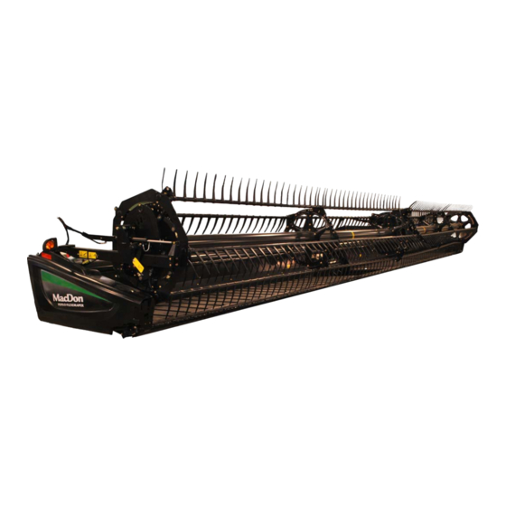
Flexdraper combine header
Hide thumbs
Also See for FD75:
- Operator's manual (578 pages) ,
- Unloading and assembly instructions (68 pages) ,
- Manual (29 pages)

Related Manuals for MacDon FD75


Summary of Contents for MacDon FD75
- Page 1 FD75 ® ® FlexDraper Combine Header Operator’s Manual 214323 Revision A 2018 Model Year Original Instruction Featuring MacDon FLEX-FLOAT Technology™ The harvesting specialists.
- Page 2 ® FD75 FlexDraper Combine Header Published: July 2017...
- Page 3 MacDon Dealer. When setting up the machine or making adjustments, review and follow the recommended machine settings in all relevant MacDon publications. Failure to do so may compromise machine function and machine life and may result in a hazardous situation.
- Page 4 Conventions The following conventions are used in this document: • Right and left are determined from the operator’s position. The front of the header is the side that faces the crop; the back of the header is the side that connects to the combine. •...
- Page 5 List of Revisions At MacDon, we’re continuously making improvements, and occasionally these improvements affect product documentation. The following list provides an account of major changes from the previous version of this document. Summary of Change Refer To Added conventions used in this document.
- Page 6 Changed “Lexion” to “CLAAS” throughout. Moved Recommended Fluids and Lubricants to inside back cover. 214323 Revision A...
-
Page 7: Model And Serial Number
Model and Serial Number Record the model number, serial number, and model year of the header, combine adapter, and transport/stabilizer wheel option (if installed) in the spaces provided. NOTE: Right and left designations are determined from the operator’s position, facing forward. Draper Header Header Model: Serial Number:... - Page 8 Slow Speed Transport/Stabilizer Wheel Option Serial Number: Year: The serial number plate (A) is located on the right axle assembly. Figure 4. Transport/Stabilizer Option 214323 Revision A...
-
Page 9: Table Of Contents
1.8 Understanding Safety Signs........................12 Chapter 2: Product Overview ......................19 2.1 Definitions ............................19 2.2 Specifications ............................21 2.3 Component Identification ........................24 ® 2.3.1 FD75 FlexDraper ........................24 2.3.2 CA25 Combine Adapter ......................25 Chapter 3: Operation ........................... 27 3.1 Owner/Operator Responsibilities......................27 3.2 Operational Safety ..........................28 3.2.1 Header Safety Props .........................28... - Page 10 TABLE OF CONTENTS 3.6.1 Header Attachments........................42 3.6.2 Header Settings ........................42 3.6.3 Optimizing Header for Straight Combining Canola ...............49 Checking and Adjusting Feed Auger Springs ................49 3.6.4 Reel Settings ..........................51 3.7 Header Operating Variables........................53 3.7.1 Cutting Height ...........................53 Cutting off the Ground.......................53 Cutting on the Ground.......................56 3.7.2 Header Float..........................58 Checking and Adjusting Header Float ..................59...
- Page 11 TABLE OF CONTENTS 3.8.2 Case IH 2300/2500 and 5088/6088/7088 Combines ..............107 Engaging Auto Header Height Control (Case IH 2300) .............. 107 Calibrating Auto Header Height Control (AHHC) (Case IH 2300/2500 and 5088/6088/ 7088) ........................108 Setting Sensitivity of Auto Header Height Control (Case IH 2300/2500 and 5088/6088/7088)......................
- Page 12 TABLE OF CONTENTS Checking Voltage Range from Combine Cab (John Deere 60 Series) ......... 165 Calibrating Auto Header Height Control (John Deere 60 Series)..........167 Turning Accumulator Off (John Deere 60 Series) ..............169 Setting Sensing Grain Header Height to 50 (John Deere 60 Series)..........169 Setting Sensitivity of Auto Header Height Control (John Deere 60 Series) ........
- Page 13 TABLE OF CONTENTS Engaging Auto Header Height Control (New Holland CR Series) ..........233 Checking Voltage Range from Combine Cab (New Holland CR Series) ........235 Calibrating Auto Header Height Control (New Holland CR Series) ..........238 Setting Auto Height (New Holland CR Series) ................241 Setting Maximum Work Height (New Holland CR Series)............
- Page 14 TABLE OF CONTENTS 4.5.1 Attaching Header to CLAAS Combine..................293 4.5.2 Detaching Header from CLAAS Combine.................. 297 4.6 New Holland Combines ........................301 4.6.1 Attaching Header to New Holland CR/CX Combine..............301 4.6.2 Detaching Header from New Holland CR/CX Combine............... 305 4.6.3 CR Feed Deflectors.........................
- Page 15 TABLE OF CONTENTS 5.7.4 Removing Auger Drive Chain ....................362 5.7.5 Installing Auger Drive Chain ..................... 366 5.7.6 Auger Tines ..........................368 Removing Feed Auger Tines ....................368 Installing Feed Auger Tines ..................... 371 Replacing Feed Auger Tine Guides..................372 5.7.7 Flighting Extensions ........................
- Page 16 TABLE OF CONTENTS 5.11.1 Removing Stripper Bars ......................416 5.11.2 Installing Stripper Bars ......................416 5.11.3 Replacing Feed Deflectors on New Holland CR Combines............417 5.12 Side Drapers ..........................418 5.12.1 Removing Side Drapers ......................418 5.12.2 Installing Side Drapers......................418 5.12.3 Checking and Adjusting Side Draper Tension ................
- Page 17 TABLE OF CONTENTS 5.14.5 Replacing Reel Drive Motor....................469 Removing Reel Drive Motor..................... 469 Installing Reel Drive Motor ...................... 470 5.14.6 Replacing Drive Chain on Double Reel ................... 471 5.14.7 Replacing Reel Speed Sensor....................472 Replacing AGCO Sensor ......................472 Replacing John Deere Sensor ....................
- Page 18 TABLE OF CONTENTS 7.2 Cutting Action and Knife Components ....................492 7.3 Reel Delivery ........................... 495 7.4 Header and Drapers......................... 498 7.5 Cutting Edible Beans........................503 Chapter 8: Reference .........................507 8.1 Torque Specifications ........................507 8.1.1 SAE Bolt Torque Specifications ....................507 8.1.2 Metric Bolt Specifications ......................
-
Page 19: Chapter 1: Safety
1 Safety 1.1 Safety Alert Symbols This safety alert symbol indicates important safety messages in this manual and on safety signs on the machine. This symbol means: • ATTENTION! • BECOME ALERT! • YOUR SAFETY IS INVOLVED! Carefully read and follow the safety message accompanying this symbol. -
Page 20: Signal Words
SAFETY 1.2 Signal Words Three signal words, DANGER, WARNING, and CAUTION, are used to alert you to hazardous situations. The appropriate signal word for each situation has been selected using the following guidelines: DANGER Indicates an imminently hazardous situation that, if not avoided, will result in death or serious injury. WARNING Indicates a potentially hazardous situation that, if not avoided, could result in death or serious injury. -
Page 21: General Safety
SAFETY 1.3 General Safety CAUTION The following are general farm safety precautions that should be part of your operating procedure for all types of machinery. Protect yourself. • When assembling, operating, and servicing machinery, wear all protective clothing and personal safety devices that could be necessary for job at hand. - Page 22 SAFETY • Wear close-fitting clothing and cover long hair. Never wear dangling items such as scarves or bracelets. • Keep all shields in place. NEVER alter or remove safety equipment. Make sure driveline guards can rotate independently of shaft and can telescope freely. •...
-
Page 23: Maintenance Safety
SAFETY 1.4 Maintenance Safety To ensure your safety while maintaining machine: • Review operator’s manual and all safety items before operation and/or maintenance of machine. • Place all controls in Neutral, stop the engine, set the park brake, remove the ignition key, and wait for all moving parts to stop before servicing, adjusting, and/or repairing. -
Page 24: Hydraulic Safety
SAFETY 1.5 Hydraulic Safety • Always place all hydraulic controls in Neutral before dismounting. • Make sure that all components in hydraulic system are kept clean and in good condition. • Replace any worn, cut, abraded, flattened, or crimped hoses and steel lines. •... -
Page 25: Safety Signs
SAFETY 1.6 Safety Signs • Keep safety signs clean and legible at all times. • Replace safety signs that are missing or become illegible. • If original parts on which a safety sign was installed are replaced, be sure repair part also bears current safety sign. -
Page 26: Safety Decal Locations
SAFETY 1.7 Safety Decal Locations Figure 1.15: Upper Cross Auger A - MD #174682 Figure 1.16: Slow Speed Transport A - MD #220799 214323 Revision A... - Page 27 SAFETY Figure 1.17: Slow Speed Transport Tow-Bar A - MD #220797 B - MD #220798 Figure 1.18: Vertical Knife A - MD #174684 214323 Revision A...
- Page 28 SAFETY Figure 1.19: Endsheets, Reel Arms, and Backsheet A - MD #174632 B - MD #131393 C - MD #184422 D - MD #131392 (Double Reel Only) E - MD #131391 F - MD #166466 G - MD #174436 214323 Revision A...
- Page 29 SAFETY Figure 1.20: Backtube A - MD #184372 B - MD #166466 C - MD #131391 D - MD #131392 E - MD #184372 (Split Frame) 214323 Revision A...
-
Page 30: Understanding Safety Signs
SAFETY 1.8 Understanding Safety Signs MD #131391 Crushing hazard DANGER • Rest header on ground or engage safety props before going under unit. Figure 1.21: MD #131391 MD #131392 Crushing hazard WARNING • To avoid injury from fall of raised reel; fully raise reel, stop the engine, remove the key, and engage safety prop on each reel support arm before working on or under reel. - Page 31 SAFETY MD #166466 High pressure oil hazard WARNING • Do not go near leaks. • High pressure oil easily punctures skin causing serious injury, gangrene, or death. • If injured, seek emergency medical help. Immediate surgery is required to remove oil. •...
- Page 32 SAFETY MD #174436 High pressure oil hazard WARNING • Do not go near leaks. • High pressure oil easily punctures skin causing serious injury, gangrene, or death. • If injured, seek emergency medical help. Immediate surgery is required to remove oil. •...
- Page 33 SAFETY MD #174684 Sharp component hazard CAUTION • Wear heavy canvas or leather gloves when working with knife. • Be sure no one is near the vertical knife when removing or rotating knife. Figure 1.30: MD #174684 MD #184371 Open drive hazard WARNING •...
- Page 34 SAFETY • Disengage header drive, put transmission in Neutral, and wait for all movement to stop before leaving operator’s position. • Stop the engine and remove the key from ignition before servicing, adjusting, lubricating, cleaning, or unplugging machine. • Engage safety props to prevent lowering of raised unit before servicing in the raised position. •...
- Page 35 SAFETY MD #193147 Transport/roading hazard WARNING • Ensure tow-bar lock mechanism is locked. Figure 1.35: MD #193147 MD #194521 Auger entanglement hazard CAUTION • To avoid injury from entanglement with rotating auger, stand clear of header/mower while machine is running. General hazard pertaining to machine operation and servicing.
- Page 36 SAFETY MD #220797 Tipping hazard in transport mode WARNING • Read the operator’s manual for more information on potential tipping or roll-over of header while transporting. Figure 1.37: MD #220797 MD #220798 Loss of control hazard in transport CAUTION • Do not tow the header with a dented or otherwise damaged tow pole (the circle with the red X shows a dent in the pole).
-
Page 37: Chapter 2: Product Overview
2 Product Overview 2.1 Definitions The following terms and acronyms may be used in this manual. Term Definition American Petroleum Institute ASTM American Society of Testing and Materials Bolt A headed and externally threaded fastener that is designed to be paired with a nut Center-link A hydraulic cylinder link between header and machine used to change header angle CGVW... - Page 38 PRODUCT OVERVIEW Term Definition A joint made with use of a fastener where joining materials are compressible or Soft joint experience relaxation over a period of time Truck A four-wheel highway/road vehicle weighing no less than 3400 kg (7500 lb.) Axial load placed on a bolt or screw, usually measured in Newtons (N) or Tension pounds (lb.)
-
Page 39: Specifications
The following symbol and letters are used in Table 2.1, page 21 and Table 2.2, page | FD75 | CA25 | Attachments S: standard / O : optional (factory installed) / O : optional (dealer installed) / -: not available Table 2.1 Header Specifications... - Page 40 PRODUCT OVERVIEW Table 2.1 Header Specifications (continued) Conveyor (Draper) and Decks Draper width 1057 mm (41.61 in.) Draper drive Hydraulic Draper speed: CA25 Combine Adapter controlled 141 m/min. (0–464 fpm) Delivery opening width 1870 mm (73.62 in.) PR15 Pick-Up Reel Quantity of tine tubes 5-, 6-, or 9-tine tubes Center tube diameter...
- Page 41 PRODUCT OVERVIEW Table 2.2 Header Attachments CA25 Combine Adapter Feed draper Width 2000 mm (78.7 in.) 107–122 m/min Feed draper Speed (350–400 fpm) Feed auger Width 1660 mm (65.3 in.) Feed auger Outside diameter 559 mm (22 in.) Feed auger Tube diameter 356 mm (14 in.) Speed (varies with...
-
Page 42: Component Identification
PRODUCT OVERVIEW 2.3 Component Identification ® ® 2.3.1 FD75 FlexDraper ® ® Figure 2.2: FD75 FlexDraper Components A - Wing Float Linkage B - Center-Link C - Center Reel Arm Prop Handle D - Transition Pan E - Reel Fore-Aft Cylinder... -
Page 43: Ca25 Combine Adapter
PRODUCT OVERVIEW 2.3.2 CA25 Combine Adapter Figure 2.3: Header Side of CA25 Combine Adapter A - Feed Auger B - Header Float Springs C - Center-Link D - Hydraulic Reservoir E - Gearbox F - Header Support Arm G - Feed Draper Figure 2.4: Combine Side of CA25 Combine Adapter A - Adapter Gearbox B - Hydraulic Compartment Cover... -
Page 45: Chapter 3: Operation
• It is your responsibility to read and understand this manual completely before operating the header. Contact your MacDon Dealer if an instruction is not clear to you. • Follow all safety messages in the manual and on safety decals on the machine. -
Page 46: Operational Safety
OPERATION 3.2 Operational Safety CAUTION Adhere to the following safety precautions: • Follow all safety and operational instructions provided in your operator’s manuals. If you do not have a combine manual, get one from your Dealer and read it thoroughly. •... -
Page 47: Reel Safety Props
OPERATION 3.2.2 Reel Safety Props The reel safety props, located on the reel support arms, prevent the reel from unexpectedly lowering. WARNING To avoid bodily injury from fall of raised reel, always engage reel safety props before going under raised reel for any reason. -
Page 48: Disengaging Reel Safety Props
OPERATION 3. Use handle (A) to move lock rod to inboard position (B) which engages pin (C) under prop. 4. Lower reel until safety props contact the outer arm cylinder mounts and the center arm pins. Figure 3.4: Reel Safety Prop – Center Arm Disengaging Reel Safety Props 1. -
Page 49: Endshields
OPERATION 3. Use the handle (B) to move the lock rod (A) to the outboard position. Figure 3.6: Reel Safety Prop – Center Arm 3.2.3 Endshields A hinged, polyethylene endshield is fitted on each end of the header. Opening Endshield 1. -
Page 50: Closing Endshield
OPERATION IMPORTANT: Do NOT force endshield once it has reached its end of travel or damage to endshield structure may result. The endshield is designed to open sufficiently to allow access to drive system and manual case. NOTE: To access the knife drive box, carefully disengage front of endshield from tab at front of endsheet and swing front of endshield away from header. -
Page 51: Removing Endshield
OPERATION 5. Replace tool (B) and lynch pin (A) on top pin (C). Figure 3.12: Left Endshield Pin Removing Endshield 1. Open the endshield. Refer to Opening Endshield, page 2. Remove the acorn nut (A) securing the endshield to support (B). 3. -
Page 52: Installing Endshield
OPERATION Installing Endshield 1. Position the endshield onto support (A), and align the hole in the endshield with stud (B) on the support. Figure 3.14: Left Endshield 2. Secure the endshield to the support with acorn nut (A). 3. Close the endshield. Refer to Closing Endshield, page NOTE: Plastic endshields may expand or contract when... -
Page 53: Adjusting Endshield
OPERATION Adjusting Endshield Polyethylene endshields expand or contract when subjected to large temperature changes. The position of the top pin and lower catch can be adjusted to compensate for dimensional changes. 1. Measure gap (X) between the front end of the endshield and the header frame and compare the measurement to the values provided in Table 3.1, page... -
Page 54: Linkage Covers
OPERATION If adjustments are required, proceed as follows: 2. Open the endshield. Refer to Opening Endshield, page 3. Loosen nut (A) on pin (B) from inside the endsheet using a 19 mm (3/4 in.) socket. 4. Close the endshield and adjust its position to achieve the gap (X) between the front end of the endshield and the header frame. -
Page 55: Installing Linkage Covers
OPERATION 2. Rotate cover (A) upward until inboard end can be lifted off. Figure 3.19: Linkage Cover Installing Linkage Covers 1. Position inboard end of cover (A) over linkage and behind indicator bar (B). 2. Lower cover until secure and against header tube. Figure 3.20: Linkage Cover 3. -
Page 56: Daily Start-Up Check
OPERATION 3.2.5 Daily Start-Up Check CAUTION • Clear the area of other persons, pets, etc. Keep children away from machinery. Walk around the machine to be sure no one is under, on, or close to it. • Wear close-fitting clothing and protective shoes with slip-resistant soles. -
Page 57: Break-In Period
OPERATION 3.3 Break-in Period CAUTION Before investigating an unusual sound or attempting to correct a problem, shut off engine and remove key. NOTE: Until you become familiar with the sound and feel of your new header, be extra attentive. After attaching the header to the combine for the first time, follow these steps: 1. -
Page 58: Shutting Down The Machine
OPERATION 3.4 Shutting down the Machine DANGER To avoid bodily injury or death from unexpected start-up of machine, always stop engine and remove key from ignition before leaving operator’s seat for any reason. To shut down, and before leaving the combine seat for any reason, follow these steps: 1. -
Page 59: Cab Controls
OPERATION 3.5 Cab Controls CAUTION Be sure all bystanders are clear of machine before starting engine or engaging any header drives. Refer to your combine operator’s manual for identification of the following in-cab controls: • Header engage/disengage control • Header height •... -
Page 60: Header Setup
OPERATION 3.6 Header Setup 3.6.1 Header Attachments ® Several attachments to improve the performance of your FD75 FlexDraper Header are available as options that can be installed by your MacDon Dealer. Refer to 6 Options and Attachments, page 479 for descriptions of available items. - Page 61 214323 Revision A...
- Page 62 OPERATION 214323 Revision A...
- Page 63 OPERATION 214323 Revision A...
- Page 64 OPERATION 214323 Revision A...
- Page 65 OPERATION 214323 Revision A...
- Page 66 OPERATION 214323 Revision A...
-
Page 67: Optimizing Header For Straight Combining Canola
3.6.3 Optimizing Header for Straight Combining Canola Ripe canola can be straight combined, but most varieties are very susceptible to shelling and subsequent seed ® loss. This section provides recommended attachments and settings to optimize FD75 FlexDraper Headers for straight combining canola. - Page 68 OPERATION 1. Raise header to full height. 2. Shut down the combine, and remove the key from the ignition. 3. Engage header lift cylinder safety props. 4. Check the thread length protruding past the nut (B). Length should be 15 mm (0.60 in.). If adjustment is required, follow these steps: 5.
-
Page 69: Reel Settings
OPERATION 3.6.4 Reel Settings NOTE: The reel settings chart is also applicable for reel tines. Table 3.4 FD75 Recommended Reel Settings Cam Setting Number Reel Position Reel Finger Pattern Number (Finger Speed Gain) 6 or 7 1 (0) 2 (20%) - Page 70 OPERATION Table 3.4 FD75 Recommended Reel Settings (continued) Reel Position Cam Setting Number Reel Finger Pattern (Finger Speed Gain) Number 3 (30%) 3 or 4 4 (35%) 2 or 3 NOTE: • Adjust the reel forward to position the fingers closer to the ground, while tilting the header back. Fingers/tines will dig into the ground at extreme reel-forward positions, so adjust skid shoes or header angle to compensate.
-
Page 71: Header Operating Variables
3.7.1 Cutting Height ® The FD75 FlexDraper Header is capable of cutting the crop to a desired stubble height or cutting as close as possible to the ground. Cutting height will vary depending on the type of crop, crop conditions, etc. - Page 72 OPERATION Adjusting Stabilizer/Slow Speed Transport Wheels A properly adjusted header will achieve a balance between the amount of header weight carried by the float and the amount carried by the stabilizer/slow speed transport wheels. Refer to 3.6.2 Header Settings, page 42 for recommended use in specific crops and crop conditions.
- Page 73 OPERATION 12. Lower the header to the desired cutting height using the combine controls and check the load indicator (A). Figure 3.26: Load Indicator IMPORTANT: Continuous operation with excessive spring compression (that is, load indicator reading greater than 4 or a compressed length [A] less than 295 mm [11-5/8 in.]) can result in damage to the suspension system.
-
Page 74: Cutting On The Ground
OPERATION 2. Support the wheel weight by lifting slightly with one hand on handle (B), and pull up on handle (A) to release the lock. 3. Lift the wheel using handle (B), and engage the support channel into center slot (C) in the upper support. 4. - Page 75 OPERATION The header float system floats the header over the surface to compensate for ridges, trenches, and other variations in ground contour to prevent the cutterbar from pushing into the ground or leaving uncut crop. Refer to the following for additional information: •...
-
Page 76: Header Float
OPERATION • Adjusting Stabilizer Wheels, page 55 • Adjusting Stabilizer/Slow Speed Transport Wheels, page 54 3. Remove lynch pin (A) from each skid shoe (B). 4. Hold shoe (B) and remove adjustment pin (C) by disengaging from the frame and pulling away from the shoe. -
Page 77: Checking And Adjusting Header Float
OPERATION 1. Set the float for cutting on the ground as follows: a. Ensure the header float locks are disengaged. Refer to Locking/Unlocking Header Float, page b. Lower feeder house using the combine header controls until float indicator (A) reaches the desired float value (cutterbar ground force). - Page 78 OPERATION 3. Adjust center-link to between B and C on indicator (A). 4. Position cutterbar 200–300 mm (8–12 in.) off the ground. 5. Stop engine and remove key from ignition. Figure 3.36: Center-Link 6. Place wing lock spring handles (A) in lock (upper) position.
- Page 79 OPERATION 8. Place stabilizer wheels and slow speed transport wheels (if equipped) in storage position as follows: a. Support wheel weight by lifting slightly with one hand, and pull up on handle (A) to release the lock. b. Lift wheels to desired height, and engage support channel into slot (B) in upper support.
- Page 80 OPERATION 10. Place supplied torque wrench (A) onto float lock (B). Note position of wrench for checking left or right side. 11. Push down on wrench to rotate bell crank (C) forward. Figure 3.41: Left Side of Adapter Figure 3.42: Right Side of Adapter 12.
- Page 81 Refer to 3.7.1 Cutting Height, page NOTE: If adequate header float cannot be achieved using all of available adjustments, an optional heavy duty spring is available. See your MacDon Dealer or refer to parts catalog for ordering information. 214323 Revision A...
-
Page 82: Locking/Unlocking Header Float
OPERATION 17. Return torque wrench (A) to its storage location at right side of adapter frame. Figure 3.45: Torque Wrench Locking/Unlocking Header Float Two header float locks—one on each side of the adapter—lock and unlock the header float system. IMPORTANT: The float locks must be engaged when the header is being transported with the adapter attached so there is no relative movement between the adapter and the header. -
Page 83: Locking/Unlocking Header Wings
Locking/Unlocking Header Wings ® The FD75 FlexDraper Header is designed to operate with the cutterbar on the ground. The three header sections move independently to follow the ground contours. In this mode, each wing is unlocked and is free to move up and down. -
Page 84: Operating In Rigid Mode
OPERATION 5. Place the torque wrench (A) on bolt (B) and use it to move the wing until the lock disengages. 6. Replace torque wrench (A) and reinstall the linkage cover. 7. The wings should now freely move up and down with equal hand force and the cutterbar should be straight. -
Page 85: Checking And Adjusting Header Wing Balance
OPERATION 5. Place torque wrench (A) on bolt (B) and use it to move the wing until the lock engages. 6. Replace torque wrench (A) and reinstall the linkage cover. NOTE: The wings will not move relative to the header. Figure 3.52: Header Wing 3.7.3 Checking and Adjusting Header Wing Balance NOTE:... - Page 86 OPERATION If a wing has a tendency to be in a smile (A) or frown (B) position, wing balance may require adjusting. Perform the following steps to verify if the wings are not balanced and the degree of imbalance: Figure 3.53: Wing Imbalance 1.
- Page 87 OPERATION NOTE: Refer to decal (A) inside each linkage cover. Figure 3.56: Linkage Cover 6. Retrieve wrench (A) from right leg of adapter. Figure 3.57: Torque Wrench 7. Place torque wrench (A) on bolt (B). Figure 3.58: Balance Linkage 214323 Revision A...
- Page 88 OPERATION 8. Check that pointer (D) is properly positioned as follows: a. Use wrench (A) to move bell crank (B) so that lower edge of bell crank is parallel to top-link (C). b. Check that pointer (D) is lined up with the top- link (C).
- Page 89 OPERATION 11. Move wing downward with torque wrench (A) until pointer upper alignment tab (C) lines up with the lower edge of top-link (B). Observe indicator reading (A) on the wrench and record it. • If the difference between the readings is 0.5 or less, the wing is balanced and no further adjustment is required.
- Page 90 OPERATION 12. Place wrench (A) back onto right leg of adapter. Figure 3.65: Torque Wrench 13. Lock the wings by moving spring handles (A) to upper LOCK position. Figure 3.66: Wing Lock in Lock Position 14. Reinstall linkage cover (A) and secure it with bolt (B). Figure 3.67: Linkage Cover 214323 Revision A...
-
Page 91: Adjusting Wing Balance
OPERATION Adjusting Wing Balance WARNING To avoid bodily injury or death from unexpected startup of machine, always stop engine and remove key before adjusting machine. Before proceeding, check the wing balance to verify how to adjust the wing. Refer to Checking Wing Balance, page NOTE: Left side is shown. - Page 92 OPERATION NOTE: Refer to decal (A) inside each linkage cover. Figure 3.70: Linkage Cover 6. Unlock the wings by moving handle (A) to lower (UNLOCK) position. Figure 3.71: Wing Lock in UNLOCK Position 7. Retrieve wrench (A) from adapter leg. Figure 3.72: Torque Wrench 214323 Revision A...
- Page 93 OPERATION 8. Place torque wrench (A) on bolt (B). Figure 3.73: Balance Linkage 9. Loosen clevis bolt (A) for the wing requiring adjustment as determined by the wing balance check. NOTE: Do NOT loosen any other hardware. Figure 3.74: Balance Linkage 10.
-
Page 94: Header Angle
16. If the cutterbar is not straight when wings are in lock mode, then further adjustments are required. Contact your MacDon Dealer. Figure 3.76: Wing Lock in Lock Position 17. Replace torque wrench on adapter frame. -
Page 95: Controlling Header Angle
OPERATION Controlling Header Angle The header/guard angle is controlled from the combine cab with a switch on the operator’s control console and an indicator on the center-link. To change the header/guard angle, adjust the length of the center-link between the combine adapter and the header. - Page 96 Choose an angle that maximizes performance for your crop and field conditions. Refer to Table 3.7, page 78 for a summary of adjustment ranges. Table 3.7 FD75 Header Angle Header Size Guard Angle 9.1–13.7 m (30–45 ft.) 2.0–7.4° Refer to 3.6.2 Header Settings, page 42...
-
Page 97: Reel Speed
Refer to Table 3.8, page 79, and contact your MacDon Dealer for ordering information. Table 3.8 Optional Reel Drive Sprockets Optional Drive Hydraulics... -
Page 98: Ground Speed
OPERATION 3.7.6 Ground Speed Operating at the proper ground speed will result in cleanly cut crops and evenly distributed material into the combine. Reduce ground speed in difficult cutting conditions to reduce loads on cutting components and drives. Use lower ground speeds in very light crops (e.g., short soybeans) to allow the reel to pull in short plants. Start at 4.8–5.8 km/h (3.0–3.5 mph) and adjust as required. -
Page 99: Adjusting Side Draper Speed
3.6.3 Optimizing Header for Straight Combining Canola, page 49 NOTE: Insufficient draper speed may be caused by low relief pressure. See your MacDon Dealer for checking and adjusting the CA25 hydraulic relief pressure. Figure 3.86: Flow Control Valve 214323 Revision A... -
Page 100: Adjusting Feed Draper Speed
OPERATION Adjusting Feed Draper Speed The feed draper moves the cut crop from the side drapers into the adapter feed auger. The adapter feed draper (A) is driven by a hydraulic motor and a pump that is powered by the combine feeder house drive through a gearbox on the adapter. -
Page 101: Checking Knife Speed
OPERATION IMPORTANT: Table 3.10 FD75 Header Knife Speed Ensure the knife speed is within the range of rpm values Recommended Knife Drive in Table 3.10, page 83. Refer to Checking Knife Speed, Speed Range (rpm) Header Size page (m [ft.]) -
Page 102: Reel Height
7. Compare pulley rpm measurement with the rpm values in the knife speed chart. Refer to 3.7.8 Knife Speed, page 8. Contact your MacDon Dealer if the pulley rpm measurement exceeds the specified rpm range for your header. 3.7.9 Reel Height The crop type and condition determines the operating height of the reel. -
Page 103: Adjusting Reel Fore-Aft Position
OPERATION A decal (A) is attached to the right reel support arm for identifying reel position. The aft edge of the cam disc (B) is the reel fore-aft position marker. For straight standing crop, center the reel over the cutterbar (4–5 on decal). - Page 104 OPERATION Reposition the center arm cylinder as follows: NOTE: Reel components not shown in illustration for improved clarity. NOTE: To move a split reel into canola position, the Short Brace Kit for Center Reel Arm (B5605) is required. 1. Position reel fully aft with support arms horizontal. 2.
- Page 105 OPERATION Reposition right arm cylinder as follows: NOTE: Reel components not shown in illustration for improved clarity. 6. Remove four bolts (A) securing cylinder bracket (B) to the reel arm. 7. Push reel back until bracket (B) lines up with the aft set of holes (C).
- Page 106 OPERATION Reposition the left reel arm cylinder as follows: NOTE: Reel components not shown in illustration for improved clarity. 9. Remove pin (A) securing cylinder (B) to bracket/light assembly (C). 10. Remove bolts (D) securing bracket/light assembly (C) to the reel arm, and remove the bracket/light assembly. 11.
-
Page 107: Repositioning Fore-Aft Cylinders With Multi-Crop Rapid Reel Conversion Option
OPERATION Repositioning Fore-Aft Cylinders with Multi-Crop Rapid Reel Conversion Option The reel can be moved approximately 227 mm (9 in.) farther aft by repositioning the fore-aft cylinders on the reel arms. DANGER To avoid bodily injury or death from unexpected start-up of machine, always stop engine and remove key from ignition before leaving operator’s seat for any reason. - Page 108 OPERATION Reposition the center arm cylinder as follows: NOTE: Reel components not shown in illustration for improved clarity. 6. Remove cotter pin (A) and clevis pin (B). 7. Push the reel back until cylinder barrel (C) lines up with the aft holes in bracket (D). 8.
-
Page 109: Reel Tine Pitch
OPERATION Reposition the right arm cylinder as follows: NOTE: Reel components not shown in illustration for improved clarity. 9. Remove cotter pin (A) and clevis pin (B). 10. Push the reel back until cylinder rod (C) lines up with the aft holes in bracket (D). 11. - Page 110 OPERATION Cam Position 1, Reel Position 6 or 7 delivers the most even crop flow onto the drapers without fluffing up or disturbing the material. • This setting will release crop close to the cutterbar and works best if the cutterbar is on the ground. •...
- Page 111 OPERATION Cam Position 4, Reel Position 2 or 3 is used with the reel fully forward to leave the maximum amount of stubble in lodged crops. • This position allows the reel to reach forward and lift the crop across the knife and onto the drapers. •...
-
Page 112: Adjusting Reel Cam
OPERATION Adjusting Reel Cam DANGER To avoid bodily injury or death from unexpected start-up of machine, always stop engine and remove key from ignition before leaving operator’s seat for any reason. 1. Turn latch pin (A) counterclockwise using a 3/4 in. wrench to release the cam disc. -
Page 113: Removing Crop Dividers Without Latch Option From Header
OPERATION 3. Lift safety lever (A). 4. Hold onto crop divider (B), push lever (C) to open latch, and lower crop divider. Figure 3.110: Crop Divider 5. Lift crop divider off endsheet and store as follows: a. Insert pin (A) on crop divider into hole in endsheet at location shown. - Page 114 OPERATION 3. Remove bolt (A), lock washer, and flat washer. 4. Lower crop divider (B) and then lift to remove from endsheet. 5. Close or install endshields. Refer to 3.2.3 Endshields, page Figure 3.112: Crop Divider 214323 Revision A...
-
Page 115: Installing Crop Dividers With Latch Option Onto Header
OPERATION Installing Crop Dividers with Latch Option onto Header DANGER To avoid bodily injury or death from unexpected start-up or fall of raised machine, always stop engine, remove key, and engage safety props before going under header for any reason. 1. -
Page 116: Installing Crop Dividers Without Latch Option Onto Header
OPERATION 7. Pull at the tip of the crop divider and ensure there is no lateral movement. If necessary, adjust bolts (A) to tighten crop divider and eliminate lateral movement. 8. Close or install endshields. Refer to 3.2.3 Endshields, page Figure 3.115: Crop Divider Installing Crop Dividers without Latch Option onto Header DANGER... -
Page 117: Crop Divider Rods
OPERATION 4. Position crop divider as shown by inserting lugs (A) into holes in endsheet. Figure 3.117: Crop Divider 5. Lift forward end of crop divider and install bolt (A) and special stepped washer (B) (step towards divider). Tighten bolt. 6. -
Page 118: Removing Crop Divider Rods
OPERATION Removing Crop Divider Rods 1. Loosen bolt (A) and remove crop divider rod (B) from both sides of header. Figure 3.119: Crop Divider Rod 2. Store both crop divider rods (A) inboard on the right endsheet. Figure 3.120: Right Endsheet Installing Crop Divider Rods 1. -
Page 119: Rice Divider Rods
OPERATION 2. Position crop divider rod (B) on tip of crop divider as shown and tighten bolt (A). 3. Repeat procedure at opposite end of header. Figure 3.122: Divider Rod on Crop Divider Rice Divider Rods Optional rice divider rods provide improved performance in tall and tangled rice crops. -
Page 120: Auto Header Height Control (Ahhc)
OPERATION 3.8 Auto Header Height Control (AHHC) MacDon’s auto header height control (AHHC) feature works in conjunction with the AHHC option available on certain combine models. A sensor is installed in float indicator box (A) on the CA25 Combine Adapter. This sensor sends a signal to combine allowing it to maintain a consistent cutting height and an optimum adapter float as header follows ground contours. -
Page 121: Sensor Output Voltage Range - Combine Requirements
OPERATION • 3.8.2 Case IH 2300/2500 and 5088/6088/7088 Combines, page 107 • 3.8.3 Case IH 5130/6130/7130, 7010/8010, 7120/8120/9120, and 7230/8230/9230 Combines, page 111 • 3.8.4 Challenger 6 and 7 Series Combines, page 122 • 3.8.5 Gleaner R62/R72 Combines, page 129 •... -
Page 122: Manually Checking Voltage Range
OPERATION Manually Checking Voltage Range The output voltage range of auto header height control (AHHC) sensors in some combines can be checked from cab. For instructions, refer to your combine operator’s manual or AHHC instructions later in this document. To manually check sensor’s output voltage range, follow these steps: 1. -
Page 123: Adjusting Voltage Limits
OPERATION 4. Use a voltmeter (A) to measure voltage between ground (Pin 2) and signal (Pin 3) wires at AHHC sensor in float indicator box. Ensure it is at high voltage limit for combine. Refer to Table 3.13, page 103. NOTE: The harness connector must be plugged into sensor. - Page 124 OPERATION 1. Complete the following steps to adjust high voltage limit: a. Extend guard angle fully; header angle indicator should be at D. b. Position header 152–254 mm (6–10 in.) above ground; float indicator should be at 0. c. Loosen sensor mounting bolts (A). d.
-
Page 125: Case Ih 2300/2500 And 5088/6088/7088 Combines
OPERATION 3.8.2 Case IH 2300/2500 and 5088/6088/7088 Combines Engaging Auto Header Height Control (Case IH 2300) NOTE: Changes may have been made to combine controls or display since this document was published. Refer to combine operator’s manual for updates. 1. Turn mode select switch (A) to HT. 2. -
Page 126: Calibrating Auto Header Height Control (Ahhc)
OPERATION Calibrating Auto Header Height Control (AHHC) (Case IH 2300/2500 and 5088/6088/7088) NOTE: Changes may have been made to combine controls or display since this document was published. Refer to combine operator’s manual for updates. To calibrate the AHHC system, follow these steps: 1. -
Page 127: Setting Sensitivity Of Auto Header Height Control
OPERATION Figure 3.137: Joystick Lever (Case IH 5088/6088/7088) NOTE: The ideal ground pressure—in most cases—is one number (on float indicator box) above header suspended off ground. For example, if float indicator needle (B) is positioned at 0 with header suspended off ground, then ideal ground pressure will be achieved with needle positioned at 1 (A). - Page 128 OPERATION 1. Use HEADER SETTINGS key (A) to display HEADER SENSITIVITY CHANGE page. 2. Use UP (B) or DOWN (C) keys to adjust highlighted item. The height sensitivity setting range is 0 (least sensitive) to 250 (most sensitive) in increments of 10. NOTE: Adjustments take effect immediately.
-
Page 129: Case Ih 5130/6130/7130, 7010/8010, 7120/8120/9120, And 7230/8230/9230 Combines
OPERATION 3.8.3 Case IH 5130/6130/7130, 7010/8010, 7120/8120/9120, and 7230/8230/9230 Combines Checking Voltage Range from Combine Cab (Case 8010) NOTE: Changes may have been made to combine controls or display since this document was published. Refer to combine operator’s manual for updates. CAUTION Check to be sure all bystanders have cleared the area. - Page 130 OPERATION 5. Select DIAG (A) on Universal display MAIN page. The DIAG page displays. 1003676 Figure 3.143: Case 8010 Combine Display 6. Select SUB SYSTEM (A). The SUB SYSTEM page displays. Figure 3.144: Case 8010 Combine Display 7. Select HDR HEIGHT/TILT (A). The SENSOR page displays.
-
Page 131: Setting Header Controls (Case 8010)
OPERATION 8. Select LEFT SEN (A). The exact voltage is displayed. Raise and lower header to see full range of voltage readings. Figure 3.146: Case 8010 Combine Display 9. Adjust voltage limits (refer to Adjusting Voltage Limits, page 105) if sensor voltage is not within low and high limits, or if range between low and high limits is insufficient (refer to Table 3.13, page... -
Page 132: Checking Voltage Range From Combine Cab
OPERATION 1. To be able to swap between reel fore/aft controls and header fore/aft tilt controls, go to the LAYOUT tab, select FORE/AFT CONTROL (A) from the legend, and place it on one of the operator configurable screens— HARV1, HARV2, HARV3 or ADJUST under the RUN menu. - Page 133 OPERATION 3. Adjust cable take-up bracket (B) (if necessary) until pointer (A) on float indicator is on 0. 1003464 Figure 3.151: Float Indicator Box 4. Ensure header float is unlocked. 5. Select DIAGNOSTICS (A) on MAIN page. The DIAGNOSTICS page opens. 6.
- Page 134 OPERATION 8. Select HEADER HEIGHT/TILT (A). The PARAMETER page opens. Figure 3.154: Case IH Combine Display 9. Select LEFT HEADER HEIGHT SEN (A), and then select GRAPH button (B). The exact voltage is displayed at top of page. Raise and lower header to see full range of voltage readings.
-
Page 135: Calibrating Auto Header Height Control
OPERATION Calibrating Auto Header Height Control (Case IH 5130/6130/7130, 7010/8010; 7120/8120/9120; 7230/8230/9230) For best performance from the auto header height control (AHHC), perform these procedures with center-link set to D. When setup and calibration are complete, adjust center-link back to desired header angle. Refer to 3.7.4 Header Angle, page NOTE:... - Page 136 OPERATION 7. Install REEL FORE-BACK (if applicable). 8. Set HEIGHT SENSITIVITY to desired value. The recommended starting point is 180. Figure 3.159: Case IH Combine Display 9. Install FORE-AFT CONTROL and HDR FORE-AFT TILT (if applicable). Figure 3.160: Case IH Combine Display 10.
-
Page 137: Software)
OPERATION Calibrating Auto Header Height Control (Case Combines with Version 28.00 or Higher Software) For best performance of the auto header height control (AHHC), perform these procedures with center-link set to D. When setup and calibration are complete, adjust center-link back to desired header angle. Refer to 3.7.4 Header Angle, page NOTE:... - Page 138 OPERATION 8. Ensure AUTO HEIGHT icon (A) appears on monitor and is displayed as shown at (B). When header is set for cutting on ground, this verifies that combine is correctly using potentiometer on header to sense ground pressure. NOTE: AUTO HEIGHT field (B) may appear on any of RUN tabs and not necessarily on RUN 1 tab.
-
Page 139: Setting Preset Cutting Height (Case 7010/8010, 7120/8120/9120, 7230/8230/9230)
OPERATION NOTE: If float was set heavier to complete ground calibration procedure, adjust to recommended operating float after calibration is complete. 13. If unit does not function properly, conduct maximum stubble height calibration. Setting Preset Cutting Height (Case 7010/8010, 7120/8120/9120, 7230/8230/9230) To set preset cutting height, follow these steps: NOTE: Changes may have been made to combine controls or display since this document was published. -
Page 140: Challenger 6 And 7 Series Combines
OPERATION NOTE: The ideal ground pressure—in most cases—is one number (on float indicator box) above header suspended off ground. For example, if float indicator needle (A) is positioned at 0 with header suspended off ground, then ideal ground pressure will be achieved with needle positioned at 1. - Page 141 OPERATION 3. Adjust cable take-up bracket (B) (if necessary) until pointer (A) on float indicator is on 0. 1003464 Figure 3.171: Float Indicator Box 4. Go to FIELD page on combine monitor, and then press diagnostics icon. The MISCELLANEOUS page displays.
-
Page 142: Engaging Auto Header Height Control (Challenger 6 Series)
OPERATION 7. Fully lower combine feeder house (adapter should be fully separated from header). NOTE: You may need to hold HEADER DOWN switch for a few seconds to ensure feeder house is fully lowered. 8. Read voltage. 9. Raise header so cutterbar is 150 mm (6 in.) off the ground. -
Page 143: Calibrating Auto Header Height Control (Challenger 6 Series)
OPERATION Calibrating Auto Header Height Control (Challenger 6 Series) NOTE: For best performance of auto header height control (AHHC) system, perform these procedures with center-link set to D. When setup and calibration are complete, adjust center-link back to desired header angle. Refer to 3.7.4 Header Angle, page NOTE:... - Page 144 OPERATION 4. Press HEADER button. The HEADER CALIBRATION page displays a warning. Figure 3.178: Challenger Combine Display 5. Read warning message, and then press green check mark button. Figure 3.179: Challenger Combine Display 6. Follow on-screen prompts to complete calibration. NOTE: The calibration procedure can be cancelled at any time by pressing cancel button in bottom right corner of...
-
Page 145: Adjusting Header Height (Challenger 6 Series)
OPERATION Adjusting Header Height (Challenger 6 Series) Once auto header height control (AHHC) is activated, press and release HEADER LOWER button on control handle. The AHHC will automatically lower header to selected height setting. NOTE: Changes may have been made to combine controls or display since this document was published. Refer to combine operator’s manual for updates. -
Page 146: Setting Sensitivity Of Auto Header Height Control (Challenger 6 Series)
OPERATION 2. Press HEADER CONTROL (A). The HEADER CONTROL page displays. Figure 3.183: Challenger Combine Display 3. Go to TABLE SETTINGS tab. 4. Press up arrow on MAX UP PWM to increase percentage number and increase raise speed; press down arrow on MAX UP PWM to decrease percentage number and decrease raise speed. -
Page 147: Gleaner R62/R72 Combines
OPERATION 2. Press HEADER CONTROL button (A). The HEADER CONTROL page appears. You can adjust sensitivity on this page using up and down arrows. Figure 3.185: Challenger Combine Display 3. Adjust sensitivity to maximum setting. 4. Activate AHHC, and press HEADER LOWER button on control handle. -
Page 148: Calibrating Auto Header Height Control (Gleaner R62/R72)
OPERATION Calibrating Auto Header Height Control (Gleaner R62/R72) For best performance of the auto header height control (AHHC), perform these procedures with center-link set to D. When setup and calibration are complete, adjust center-link back to desired header angle. Refer to 3.7.4 Header Angle, page NOTE:... - Page 149 OPERATION 1. Engage main threshing clutch (A) and header clutch (B). Figure 3.188: Combine Control Console 2. Speed throttle (A) to over 2000 rpm. Figure 3.189: Throttle 214323 Revision A...
- Page 150 OPERATION 3. Push AUTO HEADER HEIGHT button (A). The LED light (B) should flash continuously indicating that it is in standby mode and waiting for a response from Operator. Figure 3.190: Combine Header Control System 4. Briefly press HEADER DOWN button (A). The header should lower automatically and LED light should stay illuminated indicating that auto height system is engaged and working.
-
Page 151: Gleaner R65/R66/R75/R76 And S Series Combines (Except S9 Series)
OPERATION 3.8.6 Gleaner R65/R66/R75/R76 and S Series Combines (Except S9 Series) Checking Voltage Range from Combine Cab (Gleaner R65/R66/R75/R76 and S Series) NOTE: Changes may have been made to combine controls or display since this document was published. Refer to combine operator’s manual for updates. -
Page 152: Engaging Auto Header Height Control (Gleaner R65/R66/R75/R76 And S Series)
OPERATION Figure 3.195: Combine Heads-Up Display 4. Ensure header float is unlocked. 5. Press and hold button (A) on heads-up display for three seconds to enter diagnostic mode. 6. Scroll down using button (B) until LEFT is displayed on LCD screen. 7. -
Page 153: Calibrating Auto Header Height Control (Gleaner R65/R66/R75/R76 And S Series)
NOT be in auto or standby modes. The engine rpm must be above 2000 rpm. The header tilt option on 2004 and earlier model combines does NOT work with MacDon headers. This system will have to be removed and disabled in order to calibrate auto header height control (AHHC). - Page 154 OPERATION NOTE: Changes may have been made to combine controls or display since this document was published. Refer to combine operator’s manual for updates. Figure 3.198: Combine Auto Header Height Controls A - AUTO MODE Button B - AHHC Light C - CAL1 Button D - Raise Header E - Lower Header...
-
Page 155: Turning Accumulator Off (Gleaner R65/R66/R75/R76 And S Series)
OPERATION 8. Wait for HEADER TILT LEFT light (not shown) to start flashing, and then tilt header to maximum left position. 9. Press CAL2 button (G) until HEADER TILT LEFT light (not shown) stops flashing, and release button when HEADER TILT RIGHT light (not shown) begins flashing. 10. -
Page 156: Adjusting Ground Pressure (Gleaner R65/R66/R75/R76 And S Series)
OPERATION The auto header height control (AHHC) system’s stability is affected by hydraulic flow rates. Ensure that header raise (A) and header lower (B) adjustable restrictors in hydraulic valve block are adjusted so that it takes approximately six seconds to raise header from ground level to maximum height (hydraulic cylinders fully extended), and approximately six seconds to lower header from maximum height to ground level. -
Page 157: Adjusting Sensitivity Of Auto Header Height Control
OPERATION NOTE: The ideal ground pressure, in most cases, is one number of separation on AHHC from having header fully suspended off ground (B) to just resting on ground (A). Figure 3.202: Float Indicator Box Adjusting Sensitivity of Auto Header Height Control (Gleaner R65/R66/R75/R76 and S Series) NOTE: Refer to 3.8.7 Gleaner S9 Series Combines, page 142... -
Page 158: Troubleshooting Alarms And Diagnostic Faults
OPERATION When SENSITIVITY ADJUSTMENT dial (A) is set to maximum (turned completely clockwise), only small changes in ground height are needed to cause feeder house to raise or lower. In this position, cutterbar moves up and down approximately 19 mm (3/4 in.) before control module signals hydraulic control valve to raise or lower header frame. When SENSITIVITY ADJUSTMENT dial (A) is set to minimum (turned completely counterclockwise), large changes in ground height are needed to cause feeder house to raise or lower. - Page 159 OPERATION Displayed on LCD (A) as XXX cm or XX in. Figure 3.205: Combine Heads-Up Display 214323 Revision A...
-
Page 160: Gleaner S9 Series Combines
OPERATION Alarm conditions: If an error message is received from fuse panel, an audible alarm sounds. The LCD on electronic instrument panel (EIP) indicates header system in error as HDR CTRL followed by HGT ERR for height, and HDR CTRL followed by TILT ERR for tilt. - Page 161 OPERATION The AGCO Tyton terminal is used to set up and manage a MacDon draper header on an Gleaner S9 combine. The terminal has a touch screen so you can simply touch desired area on terminal screen to select an item.
- Page 162 3. Touch HEADER CONFIGURATION field (A). A page showing predefined headers opens. • If your MacDon header is already set up, it appears on header list. Touch MacDon header title (B) to highlight selection in blue, and then touch green check mark (E) to continue.
- Page 163 4. To specify type of header installed on machine, touch HEADER TYPE field (A). Figure 3.210: Header Settings 5. A list of predefined header types appears. • For MacDon Draper and FlexDraper headers, touch POWER FLOW (A). • Touch green check mark (B) to save selection and continue.
-
Page 164: Setting Up Reel Settings (Gleaner S9 Series)
Enter 40 as MacDon Reel Diameter. 8. Touch REEL PPR (Speed Pulses Per Revolution) field (B) and enter 30 as PPR value for your MacDon header. (PPR is number of teeth on reel speed sprocket. AGCO configured MacDon headers have 30 teeth on sensor pickup reel). - Page 165 OPERATION NOTE: Changes may have been made to combine controls or display since this document was published. Refer to combine operator’s manual for updates. 1. From COMBINE MAIN MENU, touch REEL SETTINGS (A) to open REEL SETTINGS page. Figure 3.216: Reel Settings on Combine Main Menu 2.
-
Page 166: Setting Up Automatic Header Controls (Gleaner S9 Series)
Changes may have been made to combine controls or display since this document was published. Refer to combine operator’s manual for updates. 1. Automatic Control Functions: There are toggle (OFF/ON) switches on HEADER SETTINGS page for automatic control functions. For MacDon headers, ensure following two functions are enabled as shown: • RTC (return to cut) (A) •... - Page 167 • Header Lateral Offset: distance between centerline of header and centerline of machine. This should be set at 0 for a MacDon header. • Feeder House to Cutter: distance from machine interface to cutterbar. This should be set at 68 for a MacDon header.
-
Page 168: Calibrating Header (Gleaner S9 Series)
OPERATION Figure 3.223: Header Settings Inputs for MacDon Headers Calibrating Header (Gleaner S9 Series) The auto header control functions are configured on HEADER SETTINGS page. CAUTION Clear the area of other persons, pets, etc. Keep children away from machinery. Walk around the machine to be sure no one is under, on, or close to it. - Page 169 Left and right header sensor (V) (values will be same with MacDon headers) • Header height sensor (mA) • Tilt position sensor (mA) The modes applicable to MacDon headers are shown with check marks below line (C): • Return to cut • Automatic header height control Figure 3.226: Header Calibration Page...
- Page 170 OPERATION 4. When sensor values are stable, touch CALIBRATE icon (A). Figure 3.228: Header Calibration 5. The hazard message warning page for HEADER CALIBRATION appears. Before proceeding with calibration by touching green check mark, make sure that all conditions on page are met. 6.
-
Page 171: Operating With A Gleaner S9 Series Combine
OPERATION 7. When calibration is complete, a message displays, and summary information (A) is shown. Green check marks confirm functions have been calibrated (B). Touch bottom green check mark (C) to save. Figure 3.231: Completed Calibration Page NOTE: On COMBINE MAIN MENU page, there is a CALIBRATION icon (A) that, when touched, opens a general CALIBRATION menu where you can directly choose from a variety of calibrations including header... - Page 172 OPERATION These are primary controls to be used to engage and use auto header height control (AHHC) function. Figure 3.233: Gleaner S9 A - Tyton Terminal B - Hydro Handle/Ground Speed Lever C - Throttle Lever D - Header Control Cluster 1.
-
Page 173: Header In-Field Settings
OPERATION 4. Use HEADER HEIGHT SETPOINT control dial (A) as necessary to fine-tune setpoint position. Figure 3.236: Header Control Cluster Header In-Field Settings NOTE: Changes may have been made to combine controls or display since this document was published. Refer to combine operator’s manual for updates. -
Page 174: John Deere 50 Series Combines
OPERATION The scroll wheel (A) is on right of Tyton terminal. Figure 3.238: Scroll Wheel for Adjustments Header height setpoint control dial (A) is on header control cluster. Figure 3.239: Header Control Cluster 3.8.8 John Deere 50 Series Combines Output Voltage Range The auto header height sensor output must be within a specific range, or feature will not work properly. - Page 175 OPERATION 1. Position header 150 mm (6 in.) above ground, and rest it on safety props. Unlock adapter float. NOTE: If header is not on down stops during next two steps, voltage may go out of range during operation causing a malfunction of auto header height control (AHHC) system.
- Page 176 OPERATION Checking Voltage Range from Combine Cab Before checking voltage range, follow these steps: 1. Position header 150 mm (6 in.) above ground, and unlock adapter float. 2. Check that float lock linkage is on down stops (washer [A] and nut [B] cannot be moved) at both locations.
- Page 177 OPERATION Figure 3.245: John Deere Combine Display 4. Press DIAGNOSTIC button (D) on monitor—dlA appears on monitor. 5. Press UP button (A) until EO1 appears on monitor—this is header adjustment. 6. Press ENTER button (C). 7. Press UP (A) or DOWN button (B) until 24 is displayed on top portion of monitor—this is voltage reading for sensor.
-
Page 178: Calibrating Auto Header Height
OPERATION Adjusting Voltage Limits 1. To adjust high voltage limit: a. Extend guard angle fully. Header angle indicator should be at D. b. Position header 150–254 mm (6–10 in.) above ground. Float indicator should be at 0. c. Loosen sensor mounting bolts (A). d. - Page 179 OPERATION 4. Press DIAGNOSTIC button (A) on monitor—dlA appears on monitor. Figure 3.247: Combine Display 5. Press CAL button (A)—dIA-CAL appears on the monitor. Figure 3.248: Combine Display 214323 Revision A...
-
Page 180: Setting Sensitivity Of Auto Header Height Control
OPERATION 6. Press UP or DOWN buttons until hdr appears on the monitor. 7. Press ENTER button—hdr H-dn appears on the monitor. 8. Fully lower feeder house to ground. NOTE: Hold HEADER DOWN switch for 5–8 seconds to ensure feeder house is fully lowered. 1003592 Figure 3.249: Combine Display 9. -
Page 181: Adjusting Threshold For Drop Rate Valve
OPERATION 1. Press DIAGNOSTIC button (A) on monitor. dIA appears on the monitor. 2. Press UP button (B) until EO1 appears on monitor, and press ENTER (D). This is header adjustment. 3. Press UP (B) or DOWN (C) button until 112 is displayed on monitor. -
Page 182: Operating Auto Header Height
OPERATION NOTE: The numbers depicted on displays in these illustrations are for reference purposes only; they are not intended to represent specific settings for your equipment. Operating Auto Header Height To operate your auto header height, follow these steps: IMPORTANT: For proper performance, deactivate accumulator (A) as described in combine’s operator’s manual. -
Page 183: John Deere 60 Series Combines
OPERATION 2. Once HEADER HEIGHT RESUME and AUTO HEADER CONTROL are turned ON, use buttons 2 (B) and 3 (C) on your hydrostatic lever for active header control. NOTE: Button 1 (A) is reserved for AUTO HEIGHT RESUME which will return header to a certain height, but will not automatically compensate for ground variation. - Page 184 OPERATION Combine Low Voltage Limit High Voltage Limit Minimum Range John Deere 60 Series 0.7 V 4.3 V 3.0 V Check sensor’s output voltage range from combine cab according to instructions that follow. NOTE: Changes may have been made to combine controls or display since this document was published. Refer to combine operator’s manual for updates.
-
Page 185: Calibrating Auto Header Height Control (John Deere 60 Series)
OPERATION Figure 3.260: John Deere Combine Display 4. Press DIAGNOSTIC button (D) on monitor—DIA appears on monitor. 5. Press UP button (A) until EO1 appears on monitor—this is header adjustment. 6. Press ENTER button (C). 7. Press UP (A) or DOWN button (B) until 24 is displayed on top portion of monitor—this is voltage reading for sensor. - Page 186 OPERATION CAUTION Check to be sure all bystanders have cleared the area. 1. Ensure center-link is set to D. 2. Rest header on down stops, and unlock adapter float. 3. Put wings in locked position. 4. Start combine. 5. Press DIAGNOSTIC button (A) on monitor. DIA appears on monitor.
-
Page 187: Turning Accumulator Off (John Deere 60 Series)
OPERATION 10. Press CAL button (A) to save calibration of header. HDR H-UP appears on monitor. 11. Raise header three feet off ground and press CAL (A) button. EOC appears on monitor. 12. Press ENTER button (B) to save calibration of header. Your AHHC is now calibrated. -
Page 188: Setting Sensitivity Of Auto Header Height Control (John Deere 60 Series)
NOTE: Do NOT use active header float function (A) in combination with MacDon auto header height control (AHHC)—the two systems will counteract one another. The header symbol (B) on display should NOT have a wavy line under it and should appear exactly as shown on Active Header Control Display in Figure 3.266, page... -
Page 189: Adjusting Threshold For Drop Rate Valve (John Deere 60 Series)
OPERATION 1. Press DIAGNOSTIC button (A) on monitor. DIA appears on the monitor. 2. Press UP button (B) until EO1 appears on monitor, and press ENTER (D). This is header adjustment. 3. Press UP (B) or DOWN (C) button until 112 is displayed on monitor. -
Page 190: John Deere 70 Series Combines
OPERATION NOTE: The numbers depicted on displays in these illustrations are for reference purposes only; they are not intended to represent specific settings for your equipment. 3.8.10 John Deere 70 Series Combines Checking Voltage Range from Combine Cab (John Deere 70 Series) The auto header height sensor output must be within a specific range, or feature will not work properly. - Page 191 OPERATION 3. Adjust cable take-up bracket (B) (if necessary) until pointer (A) on float indicator is on 0. 1003464 Figure 3.270: Float Indicator Box 4. Press HOME PAGE button (A) on main page of combine display. Figure 3.271: John Deere Combine Display 5.
- Page 192 OPERATION 6. Use scroll knob (A) to highlight middle icon (the green i) and press check mark button (B) to select it. This will display Message Center. Figure 3.273: John Deere Combine Control Console 7. Use scroll knob to highlight DIAGNOSTIC ADDRESSES (A) from right column, and then select it by pressing check mark button.
-
Page 193: Calibrating Feeder House Speed (John Deere 70 Series)
OPERATION 10. Use scroll knob to highlight down arrow (A) and press check mark button to scroll through list until 029 DATA (B) is displayed and voltage reading (C) appears on combine display. Figure 3.276: John Deere Combine Display 11. Ensure header float is unlocked. 12. - Page 194 OPERATION 5. Press button located fourth from left along top of monitor (A) to select icon that resembles an open book with a wrench on it (B). 6. Press top button (A) a second time to enter diagnostics and calibration mode. Figure 3.277: John Deere Combine Display 7.
-
Page 195: Setting Sensitivity Of Auto Header Height Control (John Deere 70 Series)
OPERATION NOTE: If an error code appears on page, sensor is not in correct working range. Refer to Checking Voltage Range from Combine Cab (John Deere 70 Series), page 172 to check and adjust range. Setting Sensitivity of Auto Header Height Control (John Deere 70 Series) NOTE: Changes may have been made to combine controls or display since this document was published. -
Page 196: John Deere S And T Series Combines
OPERATION 1. Press button (A) and current raise/lower rate setting will appear on monitor (the lower reading, slower rate). 2. Use scroll knob (B) to adjust rate. The adjustment will be saved automatically. NOTE: If page remains idle for a short period of time, it will automatically return to previous page. - Page 197 OPERATION 2. Check that float lock linkage is on down stops (washer [A] and nut [B] cannot be moved) at both locations. NOTE: If header is not on down stops during next two steps, voltage may go out of range during operation causing a malfunction of auto header height control (AHHC) system.
- Page 198 OPERATION 5. Press DIAGNOSTIC READINGS icon (A) on CALIBRATION page. The DIAGNOSTIC READINGS page appears. This page provides access to calibrations, header options, and diagnostic information. Figure 3.287: John Deere Combine Display 6. Select AHHC RESUME (A) and a list of calibration options appears.
-
Page 199: Calibrating Feeder House Fore/Aft Tilt Range (John Deere S And T Series)
• CENTER HEADER HEIGHT • RIGHT HEADER HEIGHT A reading is displayed for only center header height sensor. On MacDon header, there is only one sensor located in float indicator box on top of the CA25. Figure 3.290: John Deere Combine Display 10. - Page 200 OPERATION NOTE: The feeder house fore/aft tilt controls can be changed to work with buttons E and F by pressing hydro handle icon (A) and then selecting FEEDER HOUSE FORE/AFT TILT from drop-down menu (B) on combine display. Figure 3.292: John Deere Combine Display To calibrate feeder house fore/aft tilt range, follow these steps: 1.
- Page 201 OPERATION 5. Select CALIBRATIONS drop-down menu (A) to view list of calibration options. Figure 3.294: John Deere Combine Display 6. Press arrow (A) to cycle up though calibration options and select FEEDER HOUSE FORE/AFT TILT RANGE. Figure 3.295: John Deere Combine Display 7.
-
Page 202: Calibrating Auto Header Height Control (John Deere S And T Series)
OPERATION 8. Follow instructions that appear on combine display. As you proceed through calibration process, display will automatically update to show next step. NOTE: If an error code appears during calibration, sensor is out of voltage range and will require adjustment. Refer to Checking Voltage Range from Combine Cab (John Deere S and T Series), page 178. - Page 203 OPERATION 5. Select THRESHING CLEARANCE (A) and a list of calibration options appears. Figure 3.299: John Deere Combine Display 6. Select FEEDER HOUSE SPEED (A) and calibrate. 7. Select HEADER (B) and calibrate. Figure 3.300: John Deere Combine Display 8. Press icon (A) with either FEEDER HOUSE SPEED or HEADER selected and icon will turn green.
-
Page 204: Setting Sensitivity Of Auto Header Height Control (John Deere S And T Series)
OPERATION 9. Click button (A) and instructions will appear on screen to guide you through remaining calibration steps. NOTE: If an error code appears during calibration, sensor is out of voltage range and will require adjustment. Refer to Adjusting Voltage Limits, page 105. -
Page 205: Adjusting Manual Header Raise/Lower Rate (John Deere S And T Series)
OPERATION 2. Press – or + icon (A) to adjust rates. NOTE: The numbers depicted on displays in these illustrations are for reference purposes only; they are not intended to represent specific settings for your equipment. Figure 3.304: John Deere Combine Display Adjusting Manual Header Raise/Lower Rate (John Deere S and T Series) NOTE: Changes may have been made to the combine controls or display since this document was published. -
Page 206: Setting Preset Cutting Height (John Deere S And T Series)
OPERATION 2. Press – or + icon (A) to adjust rates. NOTE: The numbers depicted on displays in these illustrations are for reference purposes only; they are not intended to represent specific settings for your equipment. Figure 3.306: John Deere Combine Display NOTE: The ideal ground pressure—in most cases—is one number (on float indicator box) above header... - Page 207 OPERATION 2. Select COMBINE – HEADER SETUP AHC icon (A). The COMBINE – HEADER SETUP AHC screen appears. Figure 3.309: Combine Display 3. Select top-left (A) and top-center (B) icons for auto height sensing and return to cut. Figure 3.310: Combine Display 4.
- Page 208 OPERATION NOTE: The ideal ground pressure—in most cases—is one number (on float indicator box) above header suspended off ground. For example, if float indicator needle (A) is positioned at 0 with header suspended off ground, then ideal ground pressure will be achieved with needle positioned at 1.
-
Page 209: John Deere S7 Series Combines
OPERATION 3.8.12 John Deere S7 Series Combines This section applies to John Deere S7 Series combines only. Setting up Header (John Deere S7 Series) NOTE: Changes may have been made to combine controls or display since this document was published. Refer to combine operator’s manual for updates. - Page 210 OPERATION 3. Verify correct header width is displayed under WIDTH. 4. To change header width, select field (A). The WIDTH window opens. Figure 3.317: John Deere S7 Display – Header Details Window 5. Use the on-screen keypad to enter the correct header width, and then press OK.
- Page 211 OPERATION 7. The raise/lower speed, tilt speed, height sensitivity, and tilt sensitivity can all be adjusted from this page. Select the option (A) you would like to adjust. This example shows the raise/lower speed adjustment. Figure 3.320: John Deere S7 Display – Header Page 8.
-
Page 212: Checking Sensor Voltage Range (John Deere S7 Series)
OPERATION 11. If the header has not been calibrated yet, an error icon will appear on the HEIGHT SENSING button (A). Select button (A) to view error message. Figure 3.323: John Deere S7 Display – Auto Header Controls 12. Read error message and then press OK. 13. - Page 213 OPERATION 2. Check that float lock linkage is on down stops (washer [A] and nut [B] cannot be moved) at both locations. NOTE: If header is not on down stops during next two steps, voltage may go out of range during operation causing a malfunction of auto header height control (AHHC) system.
- Page 214 OPERATION 5. On the MENU page, select the SYSTEM tab (A). The MENU opens. 6. Select DIAGNOSTICS CENTER icon (B). The DIAGNOSTICS CENTER opens. Figure 3.328: John Deere S7 Display – Menu 7. Select AHC - SENSING (A). The AHC - SENSING | DIAGNOSTICS page displays.
-
Page 215: Calibrating Feeder House (John Deere S7 Series)
OPERATION Calibrating Feeder House (John Deere S7 Series) Feeder house calibration must be done before header calibration. For best performance of auto header height control (AHHC), perform these procedures with center-link set to D. When setup and calibration are complete, adjust center-link back to desired header angle. Refer to 3.7.4 Header Angle, page NOTE:... - Page 216 OPERATION 7. Select HEADER tab (A). 8. Select FEEDER HOUSE RAISE SPEED CALIBRATION (B). The FH RAISE SPEED CALIBRATION page displays. Figure 3.333: John Deere S7 Display – Calibrations and Procedures 9. Select CALIBRATE (A) at the bottom of the page. A calibration overview displays.
-
Page 217: Calibrating Header (John Deere S7 Series)
OPERATION 11. Follow the instructions on the screen. As you proceed through the calibration process, the display will automatically update to show next step. NOTE: If an error code appears during calibration, the sensor is out of voltage range and will require adjustment. Refer Adjusting Voltage Limits, page 105. - Page 218 OPERATION 4. On the HARVESTING page, select the MENU icon (A) in the bottom right corner of screen. The MENU opens. Figure 3.338: John Deere S7 Display – Harvesting Page 5. Select the MACHINE SETTINGS tab (A), 6. Select the CALIBRATIONS & PROCEDURES icon (B). The CALIBRATIONS &...
- Page 219 OPERATION 9. Select CALIBRATE (A) at bottom of page. The calibration overview window opens. Figure 3.341: John Deere S7 Display – Header Calibration 10. Press button (A) on console to set engine to high idle. Figure 3.342: John Deere S7 Console 11.
-
Page 220: Claas 500 Series Combines
OPERATION 13. When calibration is complete, select SAVE to confirm calibration. 1022828 3.8.13 CLAAS 500 Series Combines Auto Header Height Sensor Voltage Requirements The auto header height sensor output must be within a specific voltage range for the feature to work properly. Lower Voltage Limit Upper Voltage Limit Minimum Range... -
Page 221: Adjusting Voltage Limits
OPERATION 3. Measure voltage between ground and signal wires at AHHC sensor in float indicator with a voltmeter (A). NOTE: The voltage reading should be below 4.3 V. Figure 3.345: Float Indicator Reading 1 V 4. Fully lower combine feeder house until adapter is no longer supporting header. -
Page 222: Calibrating Auto Header Height Control (Claas 500 Series)
OPERATION c. Loosen potentiometer mounting bolts (C). d. Rotate potentiometer (D) clockwise to increase low voltage limit, or counterclockwise to decrease it. e. Tighten potentiometer mounting bolts (C). 3. When readings are in proper range, auto header height control can be calibrated. Calibrating Auto Header Height Control (CLAAS 500 Series) The calibration procedure determines limits of auto header height sensor. - Page 223 OPERATION 3. Use – key (A) or + key (B) to turn ON AHHC, and press OK (C). 4. Engage threshing mechanism and header. Figure 3.349: CLAAS Combine Controls 5. Use < or > key to select CUTT.HEIGHT LIMITS, and press OK.
-
Page 224: Setting Cutting Height (Claas 500 Series)
OPERATION 9. Use line (A) or value (B) to determine sensitivity setting. NOTE: The setting can be adjusted from 0–100%. When sensitivity is adjusted to 0%, signals from sensing bands have no effect on automatic cutting height adjustment. When sensitivity is adjusted to 100%, signals from sensing bands have maximum effect on automatic cutting height adjustment. -
Page 225: Setting Cutting Height Manually (Claas 500 Series)
OPERATION 6. Use < key (C) or > key (D) to select CUTTING HEIGHT page, and press OK key (E). 7. Use – key (A) or + key (B) to set desired cutting height. An arrow indicates selected cutting height on scale. Figure 3.354: CLAAS Combine Controls 8. -
Page 226: Setting Sensitivity Of Auto Header Height Control (Claas 500 Series)
OPERATION 1. Use button (A) to raise header, or button (B) to lower header to desired cutting height. 2. Press and hold button (C) for three seconds to store cutting height into CLAAS Electronic on-Board Information System (CEBIS). An alarm will sound when new setting has been stored. - Page 227 OPERATION 3. Use line (A) or value (B) to determine sensitivity setting. Figure 3.358: CLAAS Combine Display 214323 Revision A...
- Page 228 OPERATION Figure 3.359: Flow Chart for Setting Sensitivity of Float Optimizer 214323 Revision A...
-
Page 229: Adjusting Auto Reel Speed (Claas 500 Series)
OPERATION Adjusting Auto Reel Speed (CLAAS 500 Series) The reel speed can be preset when automatic header functions are activated. Follow these steps to preset reel speed. NOTE: Changes may have been made to the combine controls or display since this document was published. Refer to the combine operator’s manual for updates. - Page 230 OPERATION 4. If desired, manually adjust reel speed by rotating rotary switch to reel position (A), and then use – or + key to set reel speed. Window E15 will display selected reel speed. Figure 3.362: Combine Rotary Switch 5. Press and hold button (A) or button (B) for 3 seconds to store setting into CLAAS Electronic on-Board Information System (CEBIS).
- Page 231 OPERATION 6. Use < or > key to select REEL WINDOW. When reel window is selected, window E15 will display current advance or retard speed of reel in relation to ground speed. Figure 3.364: Combine Display Figure 3.365: Combine Display 7.
-
Page 232: Claas 700 Series Combines
OPERATION NOTE: Reel fore-aft position can also be set using joystick. 9. Press and hold button (C) or button (D) for 3 seconds to store setting into CEBIS (CLAAS Electronic on-Board Information System). An alarm will sound when the new setting has been stored. - Page 233 OPERATION 2. The pointer (A) on float indicator should point at 0. If it does not, adjust cable bracket (B) until pointer (A) on float indicator points to 0. Figure 3.368: Float Indicator with Auto Header Height Sensor 3. Measure voltage between ground and signal wires at AHHC sensor in float indicator with a voltmeter (A).
-
Page 234: Adjusting Voltage Limits
OPERATION Adjusting Voltage Limits 1. To adjust high voltage limit: a. Extend guard angle fully. Header angle indicator should be at D. b. Position header 150–254 mm (6–10 in.) above ground. Float indicator should be at 0. c. Loosen sensor mounting bolts (A). d. - Page 235 OPERATION 3. To calibrate AUTO CONTOUR, use control knob (A) to scroll left and right in top row until AUTO CONTOUR icon (B) is highlighted. Press control knob (A) to select it. Figure 3.372: CLAAS Combine Display, Console, and Joystick 4.
- Page 236 OPERATION 6. After pressing control knob, letter A and screwdriver icon (B) appear on screen (as shown). 7. Use control knob (A) to highlight the screwdriver icon (B). 8. Exit cab to engage combine separator and feeder house. 9. Press control knob (A) and a progress bar chart will appear.
-
Page 237: Setting Cutting Height (Claas 700 Series)
OPERATION Setting Cutting Height (CLAAS 700 Series) To set cutting height, follow these steps. CAUTION Check to be sure all bystanders have cleared the area. NOTE: Changes may have been made to the combine controls or display since this document was published. Refer to the combine operator’s manual for updates. - Page 238 OPERATION 1. Use control knob (A) to highlight HEADER/REEL icon (B), and press control knob (A) to select it. The HEADER/REEL dialog box opens. 2. Select HEADER icon. Figure 3.380: CLAAS Combine Display, Console, and Joystick Lever 3. Select FRONT ATTACHMENT PARAMETER SETTINGS icon (A).
-
Page 239: Adjusting Auto Reel Speed (Claas 700 Series)
OPERATION Adjusting Auto Reel Speed (CLAAS 700 Series) Adjust auto reel speed as follows: NOTE: Changes may have been made to the combine controls or display since this document was published. Refer to combine operator’s manual for updates. 1. Turn control knob (A) to highlight HEADER/REEL icon (B), and press control knob (A) to select it. - Page 240 OPERATION 3. Select ACTUAL VALUE (A) from AUTO REEL SPEED dialog menu (if you are using Auto Reel Speed). The ACTUAL VALUE indicates auto reel speed. Figure 3.385: CLAAS Combine Display, Console, and Joystick 4. Use control knob (A) to change reel speed. Figure 3.386: CLAAS Combine Display, Console, and Joystick NOTE:...
-
Page 241: New Holland Combines Cx/Cr Series (Cr Series - Model Year 2014 And Earlier)
OPERATION 3.8.15 New Holland Combines CX/CR Series (CR Series – Model Year 2014 and Earlier) NOTE: For New Holland CR models 6.80, 6.90, 7.90, 8.90, 9.90, and 10.90, refer to 3.8.16 New Holland Combines (CR Series – Model Year 2015 and Later), page 233. - Page 242 OPERATION 5. Select DIAGNOSTICS (A) on main page. The DIAGNOSTICS page displays. 6. Select SETTINGS. The SETTINGS page displays. Figure 3.390: New Holland Combine Display 7. Select GROUP drop-down arrow (A). The GROUP dialog box displays. Figure 3.391: New Holland Combine Display 8.
-
Page 243: Engaging Auto Header Height Control (New Holland Cr/Cx Series)
OPERATION 9. Select LEFT HEADER HEIGHT SEN (A), and then select GRAPH button (B). The exact voltage is displayed at top of page. 10. Raise and lower header to see full range of voltage readings. Figure 3.393: New Holland Combine Display 11. -
Page 244: Calibrating Auto Header Height Control (New Holland Cr/Cx Series)
OPERATION 3. Select HEADER AUTOFLOAT, and press ENTER. 4. Use up and down navigation keys to move between options, and select INSTALLED. 1003582 Figure 3.395: New Holland Combine Display Calibrating Auto Header Height Control (New Holland CR/CX Series) For best performance of auto header height control (AHHC), perform these procedures with center-link set to D. When setup and calibration are complete, adjust center-link back to desired header angle. - Page 245 OPERATION 2. Select HEADER (A), and press ENTER. The CALIBRATION dialog box opens. NOTE: You can use up and down navigation keys to move between options. Figure 3.396: New Holland Combine Display 3. Follow calibration steps in order in which they appear in dialog box.
-
Page 246: Adjusting Header Raise Rate (New Holland Cr/Cx Series)
OPERATION CAUTION Check to be sure all bystanders have cleared the area. 1. Select MAXIMUM STUBBLE HEIGHT calibration dialog box. As you proceed through calibration process, display will automatically update to show next step. 1003774 Figure 3.398: New Holland Calibration Dialog Box 2. -
Page 247: Setting Header Lower Rate To 50 (New Holland Cr/Cx Series)
OPERATION 1. Select HEADER RAISE RATE on combine display. 2. Use + or – buttons to change setting. 3. Press ENTER to save new setting. NOTE: The raise rate can be changed from 32 to 236 in steps of 34. The factory setting is 100. Figure 3.400: New Holland Combine Display Setting Header Lower Rate to 50 (New Holland CR/CX Series) If necessary, header lower rate (the automatic header height control button or second speed on header height... -
Page 248: Setting Preset Cutting Height (New Holland Cr/Cx Series)
OPERATION 1. Engage threshing and feeder house. 2. Select HEIGHT SENSITIVITY on combine display screen. 3. Use + or – buttons to change setting to 200. 4. Press ENTER to save new setting. NOTE: The sensitivity can be changed from 10 to 250 in steps of 10. -
Page 249: Configuring Reel Fore-Aft, Header Tilt, And Header Type (New Holland Cr Series)
OPERATION NOTE: It is not necessary to press rocker switch (D) again after adjusting. NOTE: The ideal ground pressure—in most cases—is one number (on float indicator box) above header suspended off ground. For example, if float indicator needle (A) is positioned at 0 with header suspended off ground, then ideal ground pressure will be achieved with needle positioned at 1. - Page 250 The toggle switch that was present on previous models is now configured as shown at right. MacDon headers only require first two buttons (A) and (B). The third button down (C) is not configured. Figure 3.408: New Holland Combine Controls...
-
Page 251: New Holland Combines (Cr Series - Model Year 2015 And Later)
OPERATION 3.8.16 New Holland Combines (CR Series – Model Year 2015 and Later) This section applies only to 2015 and later CR models (6.80, 6.90, 7.90, 8.90, 9.90, and 10.90). For other 3.8.15 New Holland Combines CX/CR Series (CR Series – Model Year New Holland combine models, refer to 2014 and Earlier), page 223. - Page 252 OPERATION 4. Select HEAD 1 (A). The HEADER SETUP 1 page displays. 5. Select CUTTING TYPE drop-down arrow (B) and change CUTTING TYPE to PLATFORM (C). Figure 3.411: New Holland Combine Display 6. Select HEADER SUB TYPE drop-down arrow (A). The HEADER SUB TYPE dialog box displays.
-
Page 253: Checking Voltage Range From Combine Cab (New Holland Cr Series)
OPERATION 8. Select HEAD 2 (A). The HEADER SETUP 2 page displays. Figure 3.414: New Holland Combine Display 9. Select AUTOFLOAT drop-down arrow and set AUTOFLOAT to INSTALLED (A). 10. Select AUTO HEADER LIFT drop-down arrow and set AUTO HEADER LIFT to INSTALLED (B). NOTE: With AUTO HEADER LIFT installed and AHHC engaged, header will lift up automatically when you pull... - Page 254 OPERATION CAUTION Check to be sure all bystanders have cleared the area. 1. Position header 150 mm (6 in.) above ground, and unlock adapter float. 2. Check that float lock linkage is on down stops (washer [A] and nut [B] cannot be moved) at both locations.
- Page 255 OPERATION Figure 3.419: 10 Volt AHHC Sensor Assembly 4. Ensure header float is unlocked. 5. Select DIAGNOSTICS (A) on main page. The DIAGNOSTICS page displays. Figure 3.420: New Holland Combine Display 6. Select SETTINGS (A). The SETTINGS page displays. Figure 3.421: New Holland Combine Display 214323 Revision A...
-
Page 256: Calibrating Auto Header Height Control (New Holland Cr Series)
OPERATION 7. Select HEADER HEIGHT/TILT (A) from GROUP drop-down menu. 8. Select HEADER HEIGHT SENS. L (B) from PARAMETER drop-down menu. Figure 3.422: New Holland Combine Display 9. Select GRAPH (A). The exact voltage (B) is displayed at top of page. 10. - Page 257 OPERATION • No faults have been received from Header Height Controller (HHC) module. • Header/feeder is disengaged. • Lateral float buttons are NOT pressed. • ESC key is NOT pressed. To calibrate AHHC, follow these steps: 1. Select CALIBRATIONS (A) on main page. The CALIBRATION page displays.
- Page 258 OPERATION 3. Select HEADER (A) from list of calibration options. Figure 3.426: New Holland Combine Display 4. Follow calibration steps in order in which they appear on screen. As you proceed through calibration process, display will automatically update to show next step. NOTE: Pressing ESC key during any of steps or letting system sit idle for more than three minutes will cause...
-
Page 259: Setting Auto Height (New Holland Cr Series)
The console has two buttons used for auto height presets. The toggle switch that was present on previous models is now configured as shown at right. MacDon headers only require first two buttons (A) and (B). The third button (C) is not configured. -
Page 260: Setting Maximum Work Height (New Holland Cr Series)
OPERATION 3. Select RUN tab that shows MANUAL HEIGHT. NOTE: The MANUAL HEIGHT field may appear on any of RUN tabs. When an auto height set point button is pressed, display will change to AUTO HEIGHT (A). 4. Lower header to ground. 5. -
Page 261: Replacing Auto Header Height Control (Ahhc) Sensor
OPERATION 4. Set MAXIMUM WORK HEIGHT to desired value. 5. Press SET and then press ENTER. Figure 3.434: New Holland Combine Display 3.8.17 Replacing Auto Header Height Control (AHHC) Sensor The auto header height control (AHHC) sensor/potentiometer sends a signal to combine allowing it to maintain a cutting height and optimize float as header follows ground contours. - Page 262 OPERATION 3. Position sensor control arm (A) against stop (B). 4. Install new sensor (C) onto linkage arm with wiring plug facing away from stop. 5. Pretension sensor’s internal spring by rotating sensor (C) until bolt holes align with holes on bracket. Figure 3.436: AHHC Sensor 6.
-
Page 263: Sensor Operation
OPERATION 3.8.18 Sensor Operation The position sensors supplied with auto header height control (AHHC) system are 1000 ohm (1 k) industrial series sensors containing sealed connectors. Normal operating signal voltages for sensors fall between 10% (0.5VDC) and 90% (4.5VDC). • A sensor operating with a signal voltage below 5% is considered to be shorted •... -
Page 264: Levelling The Header
OPERATION 3.9 Levelling the Header The adapter is factory-set to provide the proper level for the header and should not normally require adjustment. If the header is NOT level, perform the following checks prior to adjusting the levelling linkages: • Check that header knife drive compartments are empty. - Page 265 OPERATION NOTE: Ensure a minimum clearance of 2–3 mm (1/8 in.) (A) between the frame and the back of the bell crank lever. NOTE: Check the float after levelling header. Refer to Checking and Adjusting Header Float, page Figure 3.443: Bell Crank 214323 Revision A...
-
Page 266: Unplugging The Cutterbar
OPERATION 3.10 Unplugging the Cutterbar 1. Stop the forward movement of the machine and disengage the header drives. 2. Raise the header to prevent it from filling with dirt, and engage the header drive clutch. CAUTION Lowering rotating reel on a plugged cutterbar will damage the reel components. 3. -
Page 267: Unplugging The Adapter
OPERATION 3.11 Unplugging the Adapter 1. Stop the forward movement of the machine and disengage the header drives. 2. Raise the header slightly off the ground, and raise the reel. 3. Reverse the combine feed according to the manufacturers specifications (reverse feed varies among different combine models). -
Page 268: Upper Cross Auger (Uca)
IMPORTANT: The UCA drive motor must be equipped with a case drain kit when used on single draper drive headers. See your MacDon Dealer for details. Figure 3.444: Upper Cross Auger 3.12.1 Removing Beater Bars DANGER To avoid bodily injury or death from unexpected start-up of machine, always stop engine and remove key from ignition before leaving operator’s seat for any reason. -
Page 269: Installing Beater Bars
OPERATION 3.12.2 Installing Beater Bars WARNING To avoid bodily injury or death from unexpected startup of machine, always stop engine and remove key before adjusting machine. 1. Lower the header to the ground, stop the engine, and remove the key from the ignition. 2. -
Page 270: Transporting Header
OPERATION 3.13 Transporting Header WARNING Do NOT drive combine with header attached on a road or highway at night, or in conditions which reduce visibility, such as fog or rain. The width of the header may not be apparent under these conditions. 3.13.1 Transporting Header on Combine CAUTION •... -
Page 271: Attaching Header To Towing Vehicle
• Connect header seven-pole plug wiring harness to mating receptacle on towing vehicle. (The seven- pole receptacle is available from your MacDon Dealer parts department). • Ensure lights are functioning properly and clean the slow moving vehicle sign and other reflectors. Use flashing warning lights unless prohibited by law. -
Page 272: Converting From Transport To Field Position
OPERATION 3.13.3 Converting from Transport to Field Position Removing Tow-Bar 1. Block the tires to prevent the header from rolling, and unhook the header from the towing vehicle. 2. Disconnect the electrical connector (A) on the tow-bar. 3. Remove pin (B) from the tow-bar, and detach outer section (C) from inner section (D). -
Page 273: Storing The Tow-Bar
OPERATION Storing the Tow-Bar 1. Place the inner end of the outer half of the tow-bar into cradle (A) on the left side of the header backtube. 2. Secure clevis/pintle end of the tow-bar in support (B) on the endsheet using hitch pin (C). Secure with lynch pin. 3. -
Page 274: Moving Front (Left) Wheels Into Field Position
OPERATION 7. Attach the header to the combine. Refer to 4 Header Attachment/Detachment, page 269. 8. Place the transport wheels into field position. Refer to the following: • Moving Front (Left) Wheels into Field Position, page 256 • Moving Rear (Right) Wheels into Field Position, page 257 Moving Front (Left) Wheels into Field Position DANGER To avoid bodily injury or death from unexpected start-up or fall of raised machine, always stop engine,... -
Page 275: Moving Rear (Right) Wheels Into Field Position
OPERATION 7. Lift the wheel assembly to the desired height and slide linkage (A) into the appropriate slot in the vertical support. 8. Push handle (B) down to lock. Figure 3.454: Front (Left) Wheels Moving Rear (Right) Wheels into Field Position 1. - Page 276 OPERATION 6. Pull pin (A) on brace (B) on the left wheel in front of the cutterbar. Disengage the brace from the cutterbar, and lower the brace against axle (C). 7. Remove pin (D), lower support (E) onto axle, and reinsert pin into support.
-
Page 277: Converting From Field To Transport Position
OPERATION 13. Complete the conversion by ensuring the left side (A) and right side (B) wheels are in the position shown. Figure 3.459: Field Position 3.13.4 Converting from Field to Transport Position Moving Front (Left) Wheels into Transport Position DANGER To avoid bodily injury or death from unexpected start-up or fall of raised machine, always stop engine, remove key, and engage safety props before going under header for any reason. - Page 278 OPERATION 3. Remove the hair pin and clevis pin (A). 4. Pull latch handle (B) to release suspension linkage (C), and pull the suspension linkage away from the spindle (D). 5. Lower the wheels slowly. Figure 3.461: Left Front Wheels 6.
-
Page 279: Moving Rear (Right) Wheels Into Transport Position
OPERATION 7. Remove pin (A) from storage at the top of leg (B). 8. Move and swivel the wheels clockwise until connector (C) is turned towards the front end of the header. 9. Insert pin (A) and turn to lock. 10. - Page 280 OPERATION 6. Remove pin (A) and install at location (B) to secure the linkage. Turn the pin to lock. 7. Pull pin (D), swivel the wheel (C) counterclockwise 90°, and release the pin to lock. Figure 3.465: Wheel Position 8. Ensure the left wheel is in the transport position as shown.
- Page 281 OPERATION 10. Lock wheel (A) with pin (B). Move right axle (C) to the front of the header. Figure 3.468: Right Rear Wheel 11. Remove pin (A), raise support (B) to the position shown, and reinsert pin. IMPORTANT: Ensure pin (A) engages the tube on the axle. 12.
-
Page 282: Attaching Tow-Bar
OPERATION Attaching Tow-Bar The tow-bar consists of two sections, which make storage and handling easier. 1. Unhook rubber strap (D) from cradle (A) on the right side of the header. 2. Remove clevis pin (C) and detach the tube end from support (B). - Page 283 OPERATION 8. Connect outer half (B) of the tow-bar to inner half (A). Figure 3.472: Tow-Bar Assembly 9. Lift outer half (B) and insert it into inner half (A). Figure 3.473: Tow-Bar Assembly 10. Secure the two halves together with L-pin (A) and then turn to lock.
- Page 284 OPERATION 12. Position tow-bar (A) onto the axle, and push against latch (B) until the tow-bar pins drop into hooks (C). 13. Check that latch (B) has engaged the tow-bar. 14. Install clevis pin (D) and secure with hairpin. Figure 3.475: Attaching Tow-Bar 15.
-
Page 285: Storing The Header
OPERATION 3.14 Storing the Header Perform the following procedures at the end of each operating season: CAUTION Never use gasoline, naphtha, or any volatile material for cleaning purposes. These materials may be toxic and/or flammable. CAUTION Cover cutterbar and knife guards to prevent injury from accidental contact. 1. -
Page 287: Chapter 4: Header Attachment/Detachment
The auger speed is determined by the combine input shaft and is matched to each specific combine model; therefore, no adjustment is necessary. However, optional 20-, 22-, and 26-tooth drive sprockets are available to change the adapter feed auger speed and optimize performance. See your MacDon Dealer. 214323... -
Page 288: Case Ih Combines
HEADER ATTACHMENT/DETACHMENT 4.2 Case IH Combines 4.2.1 Attaching Header to Case IH Combine DANGER To avoid bodily injury or death from unexpected start-up of machine, always stop engine and remove key from ignition before leaving operator’s seat for any reason. 1. - Page 289 HEADER ATTACHMENT/DETACHMENT 5. On left of feeder house, lift lever (A) on adapter and push handle (B) on combine to engage locks (C) on both sides of feeder house. 6. Push down on lever (A) so slot in lever engages handle and locks handle in place.
- Page 290 HEADER ATTACHMENT/DETACHMENT 12. Position coupler onto adapter receptacle (A) and push handle (B) (not shown) to engage multicoupler pins into receptacle. 13. Push handle (B) to closed position until lock button (C) snaps out. Figure 4.6: Hydraulic Connection 14. Remove cover from electrical receptacle (A). Ensure receptacle is clean and has no signs of damage.
- Page 291 HEADER ATTACHMENT/DETACHMENT 16. Align lugs on connector (A) with slots in receptacle (B), push connector onto receptacle, and turn collar on connector to lock it in place. Figure 4.9: Electrical Connection 17. Rotate disc (A) on adapter driveline storage hook, and remove driveline from hook.
- Page 292 HEADER ATTACHMENT/DETACHMENT 19. Disengage each adapter float lock by moving latch (A) away from adapter and moving both header float lock levers (B) down (UNLOCK). Figure 4.12: Float Lock in UNLOCK Position 214323 Revision A...
-
Page 293: Detaching Header From Case Ih Combine
HEADER ATTACHMENT/DETACHMENT 4.2.2 Detaching Header from Case IH Combine DANGER To avoid bodily injury or death from unexpected start-up or fall of raised machine, always stop engine, remove key, and engage safety props before going under header for any reason. 1. - Page 294 HEADER ATTACHMENT/DETACHMENT 5. Slide the driveline into the hook (A) until the disc (B) drops securing the driveline in place. Figure 4.15: Driveline 6. Remove the electrical connector (A) and replace the cover (B). 7. Push in the lock button (C) and pull the handle (D) to release the multicoupler (E).
- Page 295 HEADER ATTACHMENT/DETACHMENT 10. Push the handle (A) on the adapter receptacle to the closed position until the lock button (B) snaps out. Close the cover (C). Figure 4.18: Adapter Receptacle 11. Lift the lever (A) and pull and lower the handle (B) to disengage the feeder house/adapter lock (C).
-
Page 296: Challenger, Gleaner, And Massey Ferguson Combines
HEADER ATTACHMENT/DETACHMENT 4.3 Challenger, Gleaner, and Massey Ferguson Combines 4.3.1 Attaching Header to Challenger, Gleaner, or Massey Ferguson Combine DANGER To avoid bodily injury or death from unexpected start-up of machine, always stop engine and remove key from ignition before leaving operator’s seat for any reason. 1. - Page 297 HEADER ATTACHMENT/DETACHMENT NOTE: Feeder house may not be exactly as shown. Figure 4.22: Alignment Pins on Feeder House 3. Raise feeder house slightly to lift header, ensuring feeder house saddle (A) is properly engaged in adapter frame. 4. Stop engine and remove key from ignition. Figure 4.23: Feeder House and Adapter 5.
- Page 298 HEADER ATTACHMENT/DETACHMENT 6. Start engine and lower header. 7. Stop engine and remove key from ignition. NOTE: The CA25 Combine Adapter is equipped with a multicoupler that connects to the combine. If combine is equipped with individual connectors, a multicoupler kit (single-point connector) must be installed. Refer to Table 4.1, page 280 for a list of kits and installation instructions that are available through your combine Dealer.
- Page 299 HEADER ATTACHMENT/DETACHMENT 9. Raise handle (A) to release multicoupler (B) from adapter. Figure 4.26: Adapter Multicoupler 10. Push handle (A) on combine to fully open position. 11. Clean mating surfaces of multicoupler (B) and receptacle if necessary. Figure 4.27: Combine Receptacle 12.
- Page 300 HEADER ATTACHMENT/DETACHMENT 14. Rotate disc (A) on adapter driveline storage hook, and remove driveline from hook. Figure 4.29: Driveline 15. Pull back collar (A) on end of driveline, and push driveline onto combine output shaft (B) until collar locks. Figure 4.30: Driveline 214323 Revision A...
-
Page 301: Detaching Header From Challenger, Gleaner, Or Massey Ferguson Combine
HEADER ATTACHMENT/DETACHMENT 4.3.2 Detaching Header from Challenger, Gleaner, or Massey Ferguson Combine DANGER To avoid bodily injury or death from unexpected start-up or fall of raised machine, always stop engine, remove key, and engage safety props before going under header for any reason. 1. - Page 302 HEADER ATTACHMENT/DETACHMENT 5. Slide the driveline into the hook (A) until the disc (B) drops securing the driveline in place. Figure 4.33: Driveline 6. Disconnect the harness at the connector (A). 7. Move the handle (B) on the combine multicoupler to the full open position to release the multicoupler (C) from the combine.
- Page 303 HEADER ATTACHMENT/DETACHMENT 10. Use the lock handle (B) to retract the lugs (A) at the base of the feeder house. Figure 4.36: Challenger and Massey Ferguson Figure 4.37: Gleaner R and S Series 11. Lower the feeder house until the saddle (A) disengages and clears the adapter support.
-
Page 304: John Deere Combines
HEADER ATTACHMENT/DETACHMENT 4.4 John Deere Combines 4.4.1 Attaching Header to John Deere Combine DANGER To avoid bodily injury or death from unexpected start-up of machine, always stop engine and remove key from ignition before leaving operator’s seat for any reason. 1. - Page 305 HEADER ATTACHMENT/DETACHMENT 6. Position multicoupler (A) onto receptacle, and pull handle (B) to engage lugs on multicoupler into the handle. 7. Pull handle (B) to a horizontal position and ensure multicoupler (A) is fully engaged into receptacle. Figure 4.41: Multicoupler 8.
- Page 306 HEADER ATTACHMENT/DETACHMENT 12. Rotate disc (A) on adapter driveline storage hook, and remove driveline from hook. Figure 4.44: Driveline 13. Pull back collar (A) on end of driveline, and push driveline onto combine output shaft (B) until collar locks. Figure 4.45: Driveline 214323 Revision A...
- Page 307 HEADER ATTACHMENT/DETACHMENT 14. Disengage each adapter float lock by moving latch (A) away from adapter and moving both header float lock levers (B) down (UNLOCK). Figure 4.46: Float Lock in UNLOCK Position 214323 Revision A...
-
Page 308: Detaching Header From John Deere Combine
HEADER ATTACHMENT/DETACHMENT 4.4.2 Detaching Header from John Deere Combine DANGER To avoid bodily injury or death from unexpected start-up or fall of raised machine, always stop engine, remove key, and engage safety props before going under header for any reason. 1. - Page 309 HEADER ATTACHMENT/DETACHMENT 5. Slide the driveline into the hook (A) until the disc (B) drops securing the driveline in place. Figure 4.49: Driveline 6. Lift the handle (A) on the adapter. Figure 4.50: Multicoupler Storage 7. Disconnect the harness (A) from the combine connector.
- Page 310 HEADER ATTACHMENT/DETACHMENT 10. Position the multicoupler (A) on the adapter receptacle and lower the handle (B) to lock the multicoupler. Figure 4.52: Multicoupler Storage 11. Push the handle (A) on the combine towards the feeder house to disengage the feeder house pin (B) from the adapter.
-
Page 311: Claas Combines
HEADER ATTACHMENT/DETACHMENT 4.5 CLAAS Combines 4.5.1 Attaching Header to CLAAS Combine DANGER To avoid bodily injury or death from unexpected start-up of machine, always stop engine and remove key from ignition before leaving operator’s seat for any reason. 1. Move handle (A) on CA25 Combine Adapter into raised position, and ensure pins (B) at bottom corners of adapter are retracted. - Page 312 HEADER ATTACHMENT/DETACHMENT 5. Remove locking pin (B) from adapter pin (A). Figure 4.57: Adapter Pin 6. Lower handle (A) to engage pins (B) into feeder house. Reinsert locking pin (C) and secure with the hairpin. 7. Stop engine and remove key from ignition. Figure 4.58: Engaging Pins 8.
- Page 313 HEADER ATTACHMENT/DETACHMENT 9. Place CA25 receptacle cover (A) onto combine receptacle. Figure 4.60: Receptacle Cover 10. Clean mating surface of coupler (A) and position onto CA25 receptacle (B). 11. Turn knob (C) to secure coupler to receptacle. 12. Connect combine harness to reel fore-aft/header tilt selector receptacle (D).
- Page 314 HEADER ATTACHMENT/DETACHMENT 14. Attach driveline (A) to combine output shaft. Figure 4.63: Driveline and Output Shaft 15. Disengage each adapter float lock by moving latch (A) away from adapter and moving both header float lock levers (B) down (UNLOCK). Figure 4.64: Float Lock in UNLOCK Position 214323 Revision A...
-
Page 315: Detaching Header From Claas Combine
HEADER ATTACHMENT/DETACHMENT 4.5.2 Detaching Header from CLAAS Combine DANGER To avoid bodily injury or death from unexpected start-up or fall of raised machine, always stop engine, remove key, and engage safety props before going under header for any reason. 1. Choose a level area and position the header slightly above the ground. - Page 316 HEADER ATTACHMENT/DETACHMENT 5. Slide the driveline into hook (A) until disc (B) drops securing the driveline in place. Figure 4.67: Driveline 6. Remove electrical connector from adapter receptacle (A). 7. Unscrew knob (B) on coupler (C) to release the coupler from adapter receptacle (D).
- Page 317 HEADER ATTACHMENT/DETACHMENT 9. Position coupler (B) onto the combine receptacle, and turn knob (A) to secure the coupler to the receptacle. Figure 4.70: Combine Coupler 10. Place cover (A) on the adapter receptacle. Figure 4.71: Adapter Receptacle Cover 11. Remove locking pin (A) from CA25 pin (B). 12.
- Page 318 HEADER ATTACHMENT/DETACHMENT 14. Lower the feeder house until the feeder house posts (A) disengage the CA25 (B). 15. Back the combine away slowly from the CA25. Figure 4.73: Header on Combine 214323 Revision A...
-
Page 319: New Holland Combines
HEADER ATTACHMENT/DETACHMENT 4.6 New Holland Combines 4.6.1 Attaching Header to New Holland CR/CX Combine DANGER To avoid bodily injury or death from unexpected start-up of machine, always stop engine and remove key from ignition before leaving operator’s seat for any reason. 1. - Page 320 HEADER ATTACHMENT/DETACHMENT 5. Lift lever (A) on CA25 on left side of feeder house, and push handle (B) on combine to engage locks (C) on both sides of feeder house. 6. Push down on lever (A) so slot in lever engages handle and locks handle in place.
- Page 321 HEADER ATTACHMENT/DETACHMENT 12. Position coupler (A) onto CA25 receptacle, and push handle (B) to engage pins into receptacle. 13. Push handle (B) to closed position until lock button (C) snaps out. 14. Remove cover on CA25 electrical receptacle. 15. Remove connector (D) from combine. 16.
- Page 322 HEADER ATTACHMENT/DETACHMENT 19. Disengage each adapter float lock by moving latch (A) away from adapter and moving both header float lock levers (B) down (UNLOCK). Figure 4.82: Float Lock in UNLOCK Position 214323 Revision A...
-
Page 323: Detaching Header From New Holland Cr/Cx Combine
HEADER ATTACHMENT/DETACHMENT 4.6.2 Detaching Header from New Holland CR/CX Combine DANGER To avoid bodily injury or death from unexpected start-up or fall of raised machine, always stop engine, remove key, and engage safety props before going under header for any reason. 1. - Page 324 HEADER ATTACHMENT/DETACHMENT 5. Slide the driveline into hook (A) until disc (B) drops securing the driveline in place. Figure 4.85: Driveline 6. Push in lock button (B), and pull handle (C) to release multicoupler (A). Figure 4.86: Adapter Connections 7. Push handle (A) to the closed position until lock button (B) snaps out.
- Page 325 HEADER ATTACHMENT/DETACHMENT 8. Position hydraulic quick coupler (A) onto storage plate (B) on the combine. Figure 4.88: Combine Coupler 9. Remove electrical connector (A) from the adapter. Figure 4.89: Adapter Connections 10. Connect the electrical connector to the combine at location (A).
- Page 326 HEADER ATTACHMENT/DETACHMENT 11. Replace cover (A) on the adapter receptacle. Figure 4.91: Adapter Receptacles 12. Lift lever (A) and pull and lower handle (B) to disengage feeder house/adapter lock (C). Figure 4.92: Feeder House Locks 13. Lower feeder house (A) until it (A) disengages from adapter support (B).
-
Page 327: Cr Feed Deflectors
HEADER ATTACHMENT/DETACHMENT 4.6.3 CR Feed Deflectors For New Holland combines only: Short feed deflectors have been factory-installed on the adapter to improve feeding into the feeder house. They may also have been installed as an option on older machines. Remove the feed deflectors if necessary. -
Page 328: Attaching And Detaching Header From Ca25 And Combine
HEADER ATTACHMENT/DETACHMENT 4.7 Attaching and Detaching Header from CA25 and Combine Attaching/detaching procedures are the same for all makes and models of combines. Headers can be attached to the CA25 from either field or transport configurations. The procedures in this manual require that the CA25 remains attached to the combine. Attach/detach the CA25 only if performing the following tasks: •... - Page 329 HEADER ATTACHMENT/DETACHMENT 6. Engage both float locks by lifting each lock lever (A) upwards until it latches into the lock position. NOTE: Stabilizer/Slow Speed Transport wheels can be used to support the header. 1009372 Figure 4.96: Float Locked 7. Remove the two hex head bolts (A) attaching filler (B) to the transition pan at the front corners.
- Page 330 HEADER ATTACHMENT/DETACHMENT 9. Remove the 9/16 in. nut from bolt (C). 10. Use a 24 mm (15/16 in.) wrench on hex bolt (B) to rotate latch (A) downwards and slightly raise the feed deck to access and remove bolt (C). 11.
- Page 331 HEADER ATTACHMENT/DETACHMENT 18. Place a 150 mm (6 in.) block (A) under the header leg. This will assist with disconnecting the center-link. 19. Disengage combine lift cylinder locks, start engine, and lower header until the header leg rests on the block or stabilizer wheels are the ground.
- Page 332 HEADER ATTACHMENT/DETACHMENT 25. Disconnect electrical connector (B). 26. Disconnect knife and draper drive hydraulic hoses (A) at bracket. Cap off ends immediately to avoid loss of oil. 27. Store and secure hoses on adapterfloat module frame. Figure 4.104: Header Connections 28.
-
Page 333: Attaching Header To Adapter And Combine
HEADER ATTACHMENT/DETACHMENT 30. Store and secure the hoses and electrical connector on the adapter at position (A) as shown. 31. Ensure the header is on the ground or is supported by the wheels in transport mode. CAUTION Never start or move the machine until you are sure all bystanders have cleared the area. - Page 334 HEADER ATTACHMENT/DETACHMENT 2. Ensure the hooks (A) are in the storage position as shown and do not interfere with the installation of the adapter arms into the channel (B). Figure 4.109: Header Underside 3. Ensure the latches (A) at the front corners of the adapter are rotated towards the rear of the adapter.
- Page 335 HEADER ATTACHMENT/DETACHMENT 8. Start engine, and lower combine feeder house so that adapter arms (B) are aligned with header balance channels (B). 9. Drive slowly forward, maintaining alignment between adapter arms (A) and header balance channels (B). 10. Keep adapter arms (A) just under the balance channels (B) to ensure adapter legs seat properly in the header linkage supports at (C).
- Page 336 HEADER ATTACHMENT/DETACHMENT CAUTION Always connect center-link before fully raising header. 15. Match the colored cable ties and connect the reel hydraulics (A) at the right end of the adapter. CAUTION Be sure all bystanders are clear of machine before starting engine or engaging any header drives. 16.
- Page 337 HEADER ATTACHMENT/DETACHMENT 24. Remove bolt (A) from both sides of the opening to allow the attachment of the adapter deck. 25. Rotate the latch (B) forward and down to engage the transition pan tube (C). Figure 4.118: Adapter Latch 26. Use a 24 mm (15/16 in.) wrench on hex bolt (B) to rotate latch (A) downwards and slightly raise the feed deck.
- Page 338 HEADER ATTACHMENT/DETACHMENT 29. Connect knife and draper drive hydraulic hoses (B) at bracket. 30. Attach electrical connector (B). Figure 4.121: Header Connections 31. Connect the quick disconnects (if installed) as follows: a. Remove the covers (if installed) from the receptacles and hose ends. b.
-
Page 339: Chapter 5: Maintenance And Servicing
5 Maintenance and Servicing The following instructions provide information about routine header service. Detailed maintenance and service information is contained in the technical service manual that is available from your Dealer. A parts catalog is provided in the plastic manual case inside the left endshield. Log hours of operation and use the maintenance record provided (refer to 5.3.1 Maintenance Schedule/Record, page... -
Page 340: Maintenance Specifications
MAINTENANCE AND SERVICING 5.2 Maintenance Specifications 5.2.1 Installing a Sealed Bearing 1. Clean the shaft and apply a rust preventive coating. 2. Install the flangette (A), bearing (B), second flangette (C), and lock the collar (D). NOTE: The locking cam is on only one side of the bearing. 3. -
Page 341: Maintenance Requirements
MAINTENANCE AND SERVICING 5.3 Maintenance Requirements Periodic maintenance requirements are organized according to service intervals. Regular maintenance is the best insurance against early wear and untimely breakdowns. Following the maintenance schedule will increase your machine’s life. When servicing the machine, refer to the appropriate section in this “Maintenance and Servicing” chapter and use only fluids and lubricants specified in Recommended Fluids and Lubricants on the inside back cover. -
Page 342: Maintenance Schedule/Record
MAINTENANCE AND SERVICING 5.3.1 Maintenance Schedule/Record Copy this page to continue record. Maintenance S S - Lubricate ▲ ▲ - Change ü ü - Check Action: Record Hour Meter Reading Date Serviced by First Use, refer to 5.3.2 Break-In Inspection, page 326 End of Season, refer to 5.3.4 End-of-Season Service, page 327 10 Hours or Daily... - Page 343 MAINTENANCE AND SERVICING Maintenance ü ü - Check S S - Lubricate ▲ ▲ - - C C h h a a n n g g e e Action: Record ü Knife drive belt tension ü Wheel bolt torque ü Knife drive box lubricant level ü...
-
Page 344: Break-In Inspection
MAINTENANCE AND SERVICING 5.3.2 Break-In Inspection Break-in inspections involve checking belts, fluids, and performing general machine inspections for loose hardware or other areas of concern. Break-in inspections ensure that all components can operate for an extended period without requiring service or replacement. Inspection Item Refer to... -
Page 345: End-Of-Season Service
MAINTENANCE AND SERVICING 5.3.4 End-of-Season Service Perform the following procedures at the end of each operating season: CAUTION Never use gasoline, naphtha or any volatile material for cleaning purposes. These materials may be toxic and/or flammable. CAUTION Cover cutterbar and knife guards to prevent injury from accidental contact. 1. -
Page 346: Checking Hydraulic Hoses And Lines
MAINTENANCE AND SERVICING 5.3.5 Checking Hydraulic Hoses and Lines Check hydraulic hoses and lines daily for signs of leaks. WARNING • Avoid high-pressure fluids. Escaping fluid can penetrate the skin causing serious injury. Relieve pressure before disconnecting hydraulic lines. Tighten all connections before applying pressure. Keep hands and body away from pin holes and nozzles which eject fluids under high pressure. -
Page 347: Service Intervals
MAINTENANCE AND SERVICING Service Intervals Every 10 Hours Use high temperature extreme pressure (EP2) performance with 1% max molybdenum disulphide (NLGI Grade 2) lithium base unless otherwise specified. Knife: Lubricate the knife every 10 hours or daily, except in sandy conditions. Figure 5.4: Every 10 Hours or Daily Every 25 Hours Use high temperature extreme pressure (EP2) performance with 1% max molybdenum disulphide (NLGI Grade 2) - Page 348 MAINTENANCE AND SERVICING Every 50 Hours Use high temperature extreme pressure (EP2) performance with 1% max molybdenum disulphide (NLGI Grade 2) lithium base unless otherwise specified. Figure 5.6: Every 50 Hours C - Driveline Slip Joint 40 A - Drive Roller Bearing B - Idler Roller Bearing (Both Sides) D - Driveline Universal (Two Places) 40.
- Page 349 MAINTENANCE AND SERVICING Every 100 Hours Use high temperature extreme pressure (EP2) performance with 1% max molybdenum disulphide (NLGI Grade 2) lithium base unless otherwise specified. Figure 5.7: Every 100 Hours A - Float Pivot - Right and Left B - Auger Drive Chain. Refer to Lubricating Auger Drive Chain, page 340 C - Driveline Guard - Two Places Lubricating Reel Drive Chain –...
- Page 350 MAINTENANCE AND SERVICING Figure 5.8: Every 100 Hours A - Knife Drive Box (Check Oil Level Between Lower Hole and End of Dipstick [B]) C - Upper Cross Auger Bearing - One Place D - Main Drive Gearbox Oil Level. Refer to Lubricating Header Drive Gearbox, page 342 214323 Revision A...
- Page 351 MAINTENANCE AND SERVICING Every 250 Hours Use high temperature extreme pressure (EP2) performance with 1% max molybdenum disulphide (NLGI Grade 2) lithium base unless otherwise specified. Figure 5.9: Every 250 Hours B - Upper Cross Auger U-Joint 41 A - Upper Cross Auger Drive Shafts (Two Places) C - Reel U-joint (One Place) D - Flex Linkage (Two Places) - Both Sides 41.
- Page 352 MAINTENANCE AND SERVICING Use high temperature extreme pressure (EP2) performance with 1% max molybdenum disulphide (NLGI Grade 2) lithium base unless otherwise specified. Figure 5.10: Every 250 Hours A - Auger Pivots B - Rear Axle Pivots C - Front Wheel Pivot (One Place) D - Frame/Wheel Pivot (One Place) - Both Sides 214323 Revision A...
- Page 353 MAINTENANCE AND SERVICING Figure 5.11: Every 250 Hours A - Double Reel U-Joint 42 42. U-joint has an extended lubrication cross and bearing kit. Stop greasing when greasing becomes difficult or if U-joint stops taking grease. Overgreasing will damage U-joint. Six to eight pumps are sufficient at first grease (factory).
- Page 354 MAINTENANCE AND SERVICING Every 500 Hours Use high temperature extreme pressure (EP2) performance with 1% max molybdenum disulphide (NLGI Grade 2) lithium base unless otherwise specified. Figure 5.12: Every 500 Hours A - Reel Right Bearing (One Place) B - Reel Center Bearing (One Place) C - Wheel Bearings (Four Places) D - Reel Left Bearing (One Place) 214323...
-
Page 355: Greasing Procedure
Refer to the inside back cover for recommended lubricants. Log hours of operation and use the Maintenance Record provided to keep a record of scheduled maintenance. Refer 5.3.1 Maintenance Schedule/Record, page 324. Figure 5.13: Greasing Interval Decal Figure 5.14: FD75 Master Grease Point Decal 214323 Revision A... - Page 356 MAINTENANCE AND SERVICING 1. Wipe grease fitting with a clean cloth before greasing to avoid injecting dirt and grit. 2. Inject grease through fitting with grease gun until grease overflows fitting (except where noted). 3. Leave excess grease on fitting to keep out dirt. 4.
-
Page 357: Lubricating Reel Drive Chain - Double Reel
MAINTENANCE AND SERVICING Lubricating Reel Drive Chain – Double Reel DANGER To avoid bodily injury or death from unexpected start-up of machine, always stop engine and remove key from ignition before leaving operator’s seat for any reason. 1. Stop the engine and remove the key from the ignition. 2. -
Page 358: Lubricating Auger Drive Chain
MAINTENANCE AND SERVICING 5. Position lower drive cover (B) onto the reel drive (if previously removed) and secure with three bolts (A). Figure 5.21: Drive Cover – Double Reel 6. Position upper drive cover (B) onto the reel drive and lower cover (C), and secure with six bolts (A). - Page 359 MAINTENANCE AND SERVICING 1. Remove the six bolts (A) securing the upper half of cover (C). 2. Loosen two bolts (B) at the rear of the cover. 3. Rotate the upper half (C) forwards to remove. Figure 5.23: Auger Drive 4.
-
Page 360: Lubricating Header Drive Gearbox
MAINTENANCE AND SERVICING 5. Reinstall the cover (C) by positioning the inboard lip into the auger tube and rotating back to engage the rear support. 6. Replace and tighten bolts (A) and (B). Figure 5.25: Auger Drive Lubricating Header Drive Gearbox Checking Oil Level in Header Drive Gearbox Check header drive gearbox oil level every 100 hours. - Page 361 MAINTENANCE AND SERVICING Adding Oil to Header Drive Gearbox DANGER To avoid bodily injury or death from unexpected start-up of machine, always stop engine and remove key from ignition before leaving operator’s seat for any reason. 1. Lower the cutterbar to the ground, and ensure the gearbox is in working position.
-
Page 362: Hydraulics
MAINTENANCE AND SERVICING 5.4 Hydraulics The CA25 Combine Adapter’s hydraulic system drives the adapter feed draper, side drapers, and knife drives. The combine’s hydraulic system drives the reel hydraulics. The adapter frame acts as an oil reservoir. Refer to the inside back cover for oil requirements. 5.4.1 Checking Oil Level in Hydraulic Reservoir Check hydraulic oil level in reservoir every 25 hours. -
Page 363: Changing Oil In Hydraulic Reservoir
MAINTENANCE AND SERVICING 1. Shut down the combine, and remove the key from the ignition. 2. Clean any dirt or debris from the filler cap (A). 3. Loosen and remove the filler cap (A) by turning it counterclockwise. 4. Add warm oil (approximately 21°C [70°F]) and fill to the required level. -
Page 364: Changing Oil Filter
MAINTENANCE AND SERVICING 5.4.4 Changing Oil Filter Change the oil filter after the first 50 hours of operation and every 250 hours thereafter. Obtain Filter Service kit (MD #183620). The kit includes one filter element, one O-ring, and one square-cut gasket. The O-ring should be used ONLY with Bosch hydraulic manifolds. - Page 365 MAINTENANCE AND SERVICING 4. Parker manifold only: If adapter fitting (A) (MD #245160) requires replacement, two nuts (1 1/2-16 UN-2A) are needed to properly torque fitting to manifold. To install adapter fitting, follow these steps: 1. Thread new adapter fitting (A) (MD #245160) into manifold (B).
-
Page 366: Electrical System
MAINTENANCE AND SERVICING 5.5 Electrical System Use electrical tape and wire clips as required to prevent wires from dragging or rubbing. Keep lights clean and replace defective bulbs. 5.5.1 Replacing Light Bulbs 1. Use a Phillips screwdriver to remove screws (A) from the fixture and remove the plastic lens. -
Page 367: Header Drive
MAINTENANCE AND SERVICING 5.6 Header Drive The header drive consists of a driveline from the combine to the CA25 Combine Adapter gearbox that drives the feed auger and a hydraulic pump. The pump provides hydraulic power to the drapers, knives, and optional equipment. -
Page 368: Installing Driveline
MAINTENANCE AND SERVICING 5.6.2 Installing Driveline DANGER To avoid bodily injury or death from unexpected start-up of machine, always stop engine and remove key from ignition before leaving operator’s seat for any reason. IMPORTANT: If the combine output shaft splines match the adapter input shaft splines, ensure the driveline is installed with the longer guard at the adapter gearbox end. -
Page 369: Removing Driveline Guard
MAINTENANCE AND SERVICING 5.6.3 Removing Driveline Guard The main driveline guard must remain attached to the driveline during operation, but it can be removed for maintenance purposes. DANGER To avoid bodily injury or death from unexpected start-up of machine, always stop engine and remove key from ignition before leaving operator’s seat for any reason. - Page 370 MAINTENANCE AND SERVICING 4. Use a slotted screwdriver to release grease zerk/lock (A). Figure 5.44: Driveline Guard 5. Rotate the driveline guard locking ring (A) counterclockwise using a screwdriver until the lugs (B) line up with the slots in the guard. 6.
-
Page 371: Installing Driveline Guard
MAINTENANCE AND SERVICING 5.6.4 Installing Driveline Guard 1. Slide the guard onto the driveline, and line up the slotted lug on the locking ring (A) with the arrow (B) on the guard. Figure 5.46: Driveline Guard 2. Push the guard onto the ring until the locking ring is visible in the slots (A). - Page 372 MAINTENANCE AND SERVICING 4. Push the grease zerk (A) back into the guard. Figure 5.49: Driveline Guard 5. Assemble the driveline. NOTE: The splines are keyed to align the universals. Align weld (A) with the missing spline (B) when assembling. Figure 5.50: Driveline 6.
-
Page 373: Adjusting Tension On Gearbox Drive Chain
MAINTENANCE AND SERVICING 5.6.5 Adjusting Tension on Gearbox Drive Chain The gearbox drive chain tension is factory-set, but tension adjustments are required every 500 hours or annually (whichever comes first). The gearbox drive chain, located inside the gearbox, requires no other regular maintenance. -
Page 374: Auger
MAINTENANCE AND SERVICING 5.7 Auger The CA25 Combine Adapter auger feeds the cut crop from the draper decks into the combine feeder house. 5.7.1 Adjusting Auger to Pan Clearance DANGER To avoid bodily injury or death from unexpected start-up of machine, always stop engine and remove key from ignition before leaving operator’s seat for any reason. -
Page 375: Checking Auger Drive Chain Tension
MAINTENANCE AND SERVICING 6. Loosen two nuts (B). 7. Use adjuster bolt (A) to set clearance (C) to 5–10 mm (3/16–3/8 in.). Turn adjuster bolt (A) clockwise to increase clearance and counterclockwise to decrease clearance. NOTE: The clearance increases 25–40 mm (1–1-1/2 in.) when center-link is fully retracted. - Page 376 MAINTENANCE AND SERVICING 5. Verify that the auger drive sprocket (A) is engaging the chain (B) completely through the adjustment slot (C). Figure 5.57: Auger Drive Sprocket (Correct) NOTE: If the auger drive sprocket (A) is not properly engaged, you will need to adjust the chain tension. Refer to 5.7.3 Adjusting Auger Drive Chain Tension, page 359.
-
Page 377: Adjusting Auger Drive Chain Tension
MAINTENANCE AND SERVICING 8. Rotate the auger (A) by hand, in forward direction, until it cannot turn anymore. 9. Measure the distance between the two lines (B). For a new chain: • If the difference (B) is 1–4 mm (0.04–0.16 in.), no adjustment is required. - Page 378 MAINTENANCE AND SERVICING 3. Remove the four bolts (A) securing the top cover to the left side of the auger chain case. 4. Remove bolts (B) on the cover retainer plate (D). 5. Remove top cover (C). Figure 5.61: Auger Drive 6.
- Page 379 MAINTENANCE AND SERVICING 11. Rotate auger (A) by hand, in the reverse direction, until it cannot turn anymore. 12. Mark a line (B) on the drum that lines up with the one of the cover supports. Figure 5.63: Auger Drive 13.
-
Page 380: Removing Auger Drive Chain
MAINTENANCE AND SERVICING 16. Install top cover (C). 17. Install four bolts (A). 18. Install bolts (B) on cover retainer plate (D). Figure 5.65: Auger Drive 5.7.4 Removing Auger Drive Chain The chain tensioner can take up slack for only a single pitch. Replace the chain when the chain has worn or stretched beyond the limits of the tensioner. - Page 381 MAINTENANCE AND SERVICING 3. Remove the four bolts (A) securing the top cover to the left side of the auger chain case. 4. Loosen bolts (B) on cover retainer plate (F). 5. Remove top cover (C) complete with cover retainer plate (F).
- Page 382 MAINTENANCE AND SERVICING 11. Remove lower bolt (A) and loosen top bolt (B). Swing C-clamp (C) up, and then slide the drive assembly to the right to allow the drive sprocket to fall off the shaft. Figure 5.68: Auger Support 12.
- Page 383 MAINTENANCE AND SERVICING NOTE: Once the drum starts sliding to the right, the drive sprocket will fall off. Figure 5.70: Auger Drive 13. Place a wooden block (A) under the drive end of the auger to prevent the auger from dropping onto the feed draper and damaging it.
-
Page 384: Installing Auger Drive Chain
MAINTENANCE AND SERVICING 15. Slide left housing (A) back into position so endless chain (B) can be removed. Figure 5.73: Auger Drive 5.7.5 Installing Auger Drive Chain 1. Place the drive chain over the sprocket on the left side of the adapter. Slide the left housing towards the drum and mount, leaving the driveshaft exposed 13 mm (1/2 in.). - Page 385 MAINTENANCE AND SERVICING 7. Loosen nut (A) securing idler sprocket (B). 8. Rotate the auger in reverse to take up the slack in the lower strand of chain (C). 9. Push down idler sprocket (B) to eliminate the remaining slack in the lower strands (C). 10.
-
Page 386: Auger Tines
MAINTENANCE AND SERVICING 18. Reinstall bottom cover (E) and drive cover retainer (G). Engage the inboard lip of the cover into the auger tube and rotate the cover back to engage the rear support. 19. Secure with bolts (D). 20. Install top cover (C) and cover retainer plate (F). 21. - Page 387 MAINTENANCE AND SERVICING 4. Remove screws (A) and remove the access cover (B) closest to the tine you are removing. Figure 5.80: Auger 5. Remove hairpin (A), pull tine (B) out of bushing (C) from inside the auger, and remove the tine from the auger by pulling it out through plastic guide (D).
- Page 388 Figure 5.83: Auger 8. Position plug (A) (MD #187137 available from MacDon Parts) into the hole from inside the auger, and secure with two socket button head screws (B). Coat the ®...
-
Page 389: Installing Feed Auger Tines
MAINTENANCE AND SERVICING Installing Feed Auger Tines DANGER To avoid bodily injury or death from unexpected start-up or fall of a raised machine, always stop engine and remove key before leaving the operator’s seat, and always engage safety props before going under the machine for any reason. -
Page 390: Replacing Feed Auger Tine Guides
MAINTENANCE AND SERVICING NOTE: If installing the #6 tine (A), it must be inserted through square drive tube (B). 7. Secure the #6 tine (A) in bushing (C) with hairpin (D). Install the hairpin with the closed end leading with respect to auger forward rotation. -
Page 391: Flighting Extensions
MAINTENANCE AND SERVICING 2. Position plastic guide (B) from inside the auger and ® secure with screws (A). Coat screws with Loctite #243 (or equivalent) and torque to 8.5 Nm (75 lbf·in). 3. Install the replacement tine. Refer to Installing Feed Auger Tines, page 371. -
Page 392: Installing Flighting Extensions
MAINTENANCE AND SERVICING 5. Replace access cover (B) and secure with screws (A). ® Coat screws with Loctite #243 (or equivalent) and torque to 8.5 Nm (75 lbf∙in). Figure 5.94: Auger Installing Flighting Extensions 1. Place flighting extensions (A) on the outboard side of auger flighting (B). - Page 393 MAINTENANCE AND SERVICING 3. Mark hole locations (A) (three per extension), and drill 76 mm (3/8 in.) holes into the auger tube. Figure 5.97: Flighting Extension 4. Install bolts to secure the flighting extensions in place. 5. Remove screws (A) and remove the nearest access cover (B).
-
Page 394: Knife
MAINTENANCE AND SERVICING 5.8 Knife WARNING Keep hands clear of the area between guards and knife at all times. CAUTION To avoid personal injury, before servicing machine or opening drive covers, refer to 5.1 Preparing Machine for Servicing, page 321. CAUTION Wear heavy gloves when working around or handling knives. -
Page 395: Removing Knife
MAINTENANCE AND SERVICING 7. Reposition bars (C) and/or (D) on knife (A) and install lock nuts (B). NOTE: If replacing screws, ensure they are fully inserted. Do not use nuts to draw screws into the knife bar. 8. Torque nuts to 9.5 Nm (7 lbf∙ft). Figure 5.101: Knife Bar 5.8.2 Removing Knife WARNING... -
Page 396: Removing Knifehead Bearing
MAINTENANCE AND SERVICING 5.8.3 Removing Knifehead Bearing WARNING To avoid bodily injury or death from unexpected start-up or fall of raised machine, always stop engine, remove key, and engage safety props before going under machine for any reason. WARNING Stand to rear of knife during removal to reduce risk of injury from cutting edges. Wear heavy gloves when handling knife. -
Page 397: Installing Knifehead Bearing
MAINTENANCE AND SERVICING 5.8.4 Installing Knifehead Bearing 1. Place O-ring (E) and plug (D) into knifehead. IMPORTANT: Install the bearing with the stamped end (the end with the identification markings) facing up. 2. Use a flat-ended tool with the same approximate diameter as bearing (C), and push the bearing into the knifehead until the top of the bearing is flush with the step in the knifehead. -
Page 398: Spare Knife
To avoid bodily injury or death from unexpected start-up or fall of raised machine, always stop engine, remove key, and engage safety props before going under machine for any reason. NOTE: Use guard straightening tool (MD #140135) available from your MacDon Dealer. 214323 Revision A... -
Page 399: Replacing Pointed Guards
NOTE: If crop is difficult to cut, install stub guards with top guards and adjuster plates. A kit is available from your MacDon Dealer. Refer to 6.3.3 Stub Guard Conversion Kit, page 482. Figure 5.109: Downward Adjustment... - Page 400 MAINTENANCE AND SERVICING 1. Shut down the combine, and remove the key from the ignition. 2. Stroke the knife manually until the knife sections are spaced midway between the guards. 3. Remove two nuts (B) and bolts attaching guard (A) and hold-down (C) (if applicable) to the cutterbar.
-
Page 401: Replacing Stub Guards
MAINTENANCE AND SERVICING Center guard replacement WARNING To avoid bodily injury or death from unexpected start-up or fall of raised machine, always stop engine, remove key, and engage safety props before going under machine for any reason. 1. Shut down the combine, and remove the key from the ignition. - Page 402 MAINTENANCE AND SERVICING 1. Shut down the combine, and remove the key from the ignition. 2. Stroke the knife manually until the knife sections are spaced midway between the guards. 3. Remove the two nuts (A) and bolts attaching the guard (B) and hold-down (C) to the cutterbar.
- Page 403 MAINTENANCE AND SERVICING 5. Position the plastic wearplate (if applicable), replacement guard (B), adjuster bar (D), hold-down (C), and install bolts and nuts (A). Do NOT tighten. 6. Check and adjust the clearance between the hold- downs and the knife. Refer to Checking and Adjusting Knife Hold-Downs, page 386.
-
Page 404: Checking And Adjusting Knife Hold-Downs
MAINTENANCE AND SERVICING 7. Shut down the combine, and remove the key from the ignition. 8. Remove the two nuts (A) and bolts attaching the guard (B), hold-down (C), and adjuster bar (D) to the cutterbar. 9. Remove guard (B), plastic wearplate (if installed), hold- down (C), and adjuster bar (D). - Page 405 MAINTENANCE AND SERVICING 1. Shut down combine, and remove key from ignition. 2. Manually stroke knife to locate section (A) under hold- down (B). 3. At standard guard locations, push knife section (A) down against guard (C) and measure clearance between hold-down (B) and knife section (A) with a feeler gauge.
- Page 406 MAINTENANCE AND SERVICING 1. Shut down combine, and remove key from ignition. 2. Decrease clearance by turning bolt (B) clockwise to lower front of hold-down (A). 3. Increase clearance by turning bolt (B) counterclockwise to raise front of hold-down. NOTE: For larger adjustments, it may be necessary to loosen nuts (C), turn adjuster bolt (B), and then retighten nuts.
- Page 407 MAINTENANCE AND SERVICING Checking Stub Guard Hold-Downs This procedure is applicable to single- and double-knife headers with stub guards. WARNING To avoid bodily injury or death from unexpected startup of machine, always stop engine and remove key before adjusting machine. Measure clearance between hold-downs and knife sections as follows: 1.
- Page 408 MAINTENANCE AND SERVICING 5. Double-knife center stub guard: Manually stroke knife to locate sections under hold-down (B). 6. Measure clearance between knife sections (A) and (C) with a feeler gauge. The clearance should be as follows: • At hold-down tip (E): 0.1–0.4 mm (0.004–0.016 in.) •...
-
Page 409: Knifehead Shield
The knifehead shield attaches to the endsheet and reduces the knifehead opening to prevent cut crop from accumulating in the knifehead cut-out. The shields and mounting hardware are available from your MacDon Dealer. IMPORTANT: Remove the shields when cutting with the cutterbar on the ground in muddy conditions. Mud may pack into the cavity behind the shield which could result in knife drive box failure. -
Page 410: Installing Knifehead Shield
MAINTENANCE AND SERVICING Installing Knifehead Shield The knifehead shield is supplied in flattened form, but it can be bent to suit installation on pointed or stub guard cutterbars. Knifehead shields differ slightly depending on header size and guard configuration, so ensure you are using the proper knifehead shield for your header. -
Page 411: Knife Drive
MAINTENANCE AND SERVICING 5.9 Knife Drive 5.9.1 Knife Drive Box Knife drive boxes convert rotational motion into the reciprocating motion of the knife, and are belt driven by a hydraulic motor that is powered by the hydraulic pump on the adapter. There is one knife drive box on single-reel headers and two knife drive boxes on double-reel headers. -
Page 412: Removing Knife Drive Box
MAINTENANCE AND SERVICING Removing Knife Drive Box DANGER To avoid bodily injury or death from unexpected start-up or fall of a raised machine, always stop engine and remove key before leaving the operator’s seat, and always engage safety props before going under the machine for any reason. - Page 413 MAINTENANCE AND SERVICING 6. Remove belt (A) from drive pulley (B). 7. Slip belt (A) over and behind knife drive box pulley (C). Use the notch in the pulley to assist with belt removal. Figure 5.133: Knife Drive 8. Stroke the knife manually to its outer limit. 9.
-
Page 414: Removing Knife Drive Box Pulley
MAINTENANCE AND SERVICING 15. Remove bolt (A) that clamps the knife drive arm to the knife drive box output shaft. 16. Remove knife drive arm (B) from the knife drive box output shaft. 17. Remove the four knife drive box mounting bolts (C) and (D). -
Page 415: Installing Knife Drive Box Pulley
MAINTENANCE AND SERVICING Installing Knife Drive Box Pulley 1. Ensure the splines and bores in the pulley and drive arm are free of paint, oil, and solvents. ® 2. Apply two bands (A) of Loctite #243 adhesive (or equivalent) around the shaft as shown. Apply one band at the end of the spline and the second band at the approximate midpoint location. - Page 416 MAINTENANCE AND SERVICING ® 4. Apply two bands (A) of Loctite #243 (or equivalent) to the output shaft as shown. Apply one band at the end of the output shaft and the second band at the approximate midpoint location. 5. Slide output arm (B) onto the output shaft. Rotate the pulley to ensure the splines are properly aligned and the drive arm clears the frame on the inboard stroke.
- Page 417 15. Move the output arm to the midstroke position, and ensure the knife bar doesn’t contact the front of the first guard. If the knife drive box requires adjustment, contact your MacDon Dealer. 16. Install and tension the knife drive belts. Refer to Tensioning Knife Drive Belts, page 402 17.
-
Page 418: Changing Oil In Knife Drive Box
MAINTENANCE AND SERVICING Changing Oil in Knife Drive Box Change the knife drive box lubricant after the first 50 hours of operation and every 1000 hours (or 3 years) thereafter. 1. Shut down the combine, and remove the key from the ignition. - Page 419 MAINTENANCE AND SERVICING 1. Shut down the combine, and remove the key from the ignition. 2. Open the endshield. 3. Loosen the two bolts (A) securing the motor assembly to the header endsheet. 4. Loosen the belt tension by turning tensioning bolt (B) counterclockwise.
- Page 420 MAINTENANCE AND SERVICING Installing Knife Drive Belts The procedure for installing non-timed knife drive belts is the same for both sides of the header. DANGER To avoid bodily injury or death from unexpected start-up or fall of a raised machine, always stop engine and remove key before leaving the operator’s seat, and always engage safety props before going under the machine for any reason.
- Page 421 MAINTENANCE AND SERVICING 1. Shut down machine, and remove key from the ignition. 2. Open the endshield. 3. Loosen the two bolts (A) securing the motor assembly to the header endsheet. 4. Turn adjuster bolt (B) clockwise to move drive motor until a force of 89 N (20 lbf) deflects belt (C) 20–25 mm (3/4–1 in.) at midspan.
-
Page 422: Adapter Feed Draper
MAINTENANCE AND SERVICING 5.10 Adapter Feed Draper CAUTION To avoid personal injury, before servicing machine or opening drive covers, refer to 5.1 Preparing Machine for Servicing, page 321. 5.10.1 Replacing CA25 Feed Draper Replace draper if torn, cracked, or missing slats. DANGER To avoid bodily injury or death from unexpected start-up or fall of a raised machine, always stop engine and remove key before leaving the operator’s seat, and always engage safety props before going under... -
Page 423: Adjusting Ca25 Feed Draper Tension
MAINTENANCE AND SERVICING 8. Install the new draper over drive roller (A) with the chevron cleat (B) pointing towards the front of the adapter. Make sure the draper guides fit in drive roller grooves (C). 9. Pull the draper along the bottom of the adapter deck and over draper supports (D). -
Page 424: Adapter Drive Roller
MAINTENANCE AND SERVICING 3. Ensure the draper guide (rubber track on the underside of the draper) is properly engaged in the groove of the drive roller and the idler roller is between the guides. NOTE: The default position of spring retainer (A) is flush to the edge of spring box (B);... - Page 425 MAINTENANCE AND SERVICING 4. Loosen jam nut (A) and hold nut (B) with a wrench while turning bolt (C) counterclockwise to release the draper tension. Repeat at the opposite side. Figure 5.159: Tensioner 5. Remove screws (A) and nuts, and remove the draper connector straps (B).
-
Page 426: Installing Ca25 Feed Draper Drive Roller
MAINTENANCE AND SERVICING 10. Remove the four bolts (A) securing hydraulic motor (B) to the frame. Slide the hydraulic motor away from drive roller (C). 11. Remove drive roller (C). Figure 5.162: Hydraulic Motor Installing CA25 Feed Draper Drive Roller 1. -
Page 427: Replacing Adapter Feed Draper Drive Roller Bearing
MAINTENANCE AND SERVICING Replacing Adapter Feed Draper Drive Roller Bearing Removing CA25 Feed Draper Drive Roller Bearing DANGER To avoid bodily injury or death from unexpected start-up or fall of a raised machine, always stop engine and remove key before leaving the operator’s seat, and always engage safety props before going under the machine for any reason. -
Page 428: Adapter Idler Roller
MAINTENANCE AND SERVICING Installing CA25 Feed Draper Drive Roller Bearing 1. Install bearing flanges (C) and the bearing. 2. Install three bolts (B) to secure the bearing and flanges (C) to the feed deck. 3. Lock bearing collar (A) and tighten the setscrew. 4. -
Page 429: Replacing Adapter Feed Draper Idler Roller Bearing
MAINTENANCE AND SERVICING 4. Remove screws (A) and nuts, and remove the draper connector straps (B). 5. Open the feed draper. Figure 5.169: Draper Connector 6. Remove two bolts (A) and nuts (C) from both ends of the idler roller. 7. - Page 430 MAINTENANCE AND SERVICING 2. Remove nut (A). 3. Use a hammer to tap bearing assembly (B) until it slides off the shaft. Figure 5.172: Idler Roller 4. Secure housing (D) and remove internal retaining ring (A), bearing (B), and two seals (C). 5.
-
Page 431: Installing Ca25 Feed Draper Idler Roller
MAINTENANCE AND SERVICING Installing CA25 Feed Draper Idler Roller 1. Position idler roller assembly (B) in the feed deck. 2. Install two bolts (A) and nuts (C) at both ends of the idler roller. Figure 5.175: Idler Roller 3. Close the feed draper and secure with connector straps (B), screws (A), and nuts. - Page 432 MAINTENANCE AND SERVICING 3. Rotate latches (A) to unlock handles (B). 4. Hold pan (C) and rotate handles (B) downward to release pan. Figure 5.177: Feed Deck Polyethylene Door 5. Lower plastic pan (A) and check for debris that may have fallen under adapter draper.
-
Page 433: Raising Polyethylene Door - Adapter Feed Deck
MAINTENANCE AND SERVICING 5.10.6 Raising Polyethylene Door – Adapter Feed Deck 1. Raise plastic pan (A). 2. Attach hooks (B) to lock handle (C). IMPORTANT: Ensure all three hooks are secured. Figure 5.179: Feed Deck Polyethylene Door 3. Hold pan (C) and rotate handles (B) upward to secure pan. -
Page 434: Adapter Stripper Bars And Feed Deflectors
MAINTENANCE AND SERVICING 5.11 Adapter Stripper Bars and Feed Deflectors 5.11.1 Removing Stripper Bars 1. Detach the header from the combine. Refer to 4 Header Attachment/Detachment, page 269. 2. Remove the four bolts and nuts (A) securing stripper bar (B) to the adapter frame, and remove the stripper bar. -
Page 435: Replacing Feed Deflectors On New Holland Cr Combines
MAINTENANCE AND SERVICING 5.11.3 Replacing Feed Deflectors on New Holland CR Combines 1. Detach the header from the combine. Refer to 4 Header Attachment/Detachment, page 269. 2. Measure gap (B) between existing feed deflector (A) and the forward edge of the pan. Figure 5.183: Feed Deflector –... -
Page 436: Side Drapers
MAINTENANCE AND SERVICING 5.12 Side Drapers Two side drapers convey cut crop to the adapter’s feed draper and auger. Replace side drapers if torn, cracked, or missing slats. 5.12.1 Removing Side Drapers DANGER To avoid bodily injury or death from unexpected start-up or fall of a raised machine, always stop engine and remove key before leaving the operator’s seat, and always engage safety props before going under the machine for any reason. - Page 437 MAINTENANCE AND SERVICING 1. Apply talc, baby powder, or talc/graphite lubricant mix to the draper surface that forms the seal with the cutterbar and to the underside of the draper guides. 2. Insert the draper into the deck at the outboard end under the rollers.
-
Page 438: Checking And Adjusting Side Draper Tension
MAINTENANCE AND SERVICING 8. Check the draper seal between the drapers and the cutterbar. Ensure there is a 1–2 mm (0.04–0.08 in.) gap (A) between cutterbar (C) and draper (B). 9. Refer to 5.12.5 Adjusting Deck Height, page 424 achieve the proper gap. Figure 5.189: Draper Seal 5.12.3 Checking and Adjusting Side Draper Tension WARNING... - Page 439 MAINTENANCE AND SERVICING To adjust draper tension, follow these steps: CAUTION Check to be sure all bystanders have cleared the area. 1. Start engine and raise header. 2. Stop engine, remove key from ignition, and engage header safety props. 3. Check that draper guide (rubber track on underside of draper) is properly engaged in groove (A) of drive roller.
-
Page 440: Adjusting Side Draper Tracking
MAINTENANCE AND SERVICING IMPORTANT: Do NOT adjust nut (C). This nut is used for draper alignment only. 5. If draper is too tight, turn adjuster bolt (A) counterclockwise to loosen draper. The white indicator bar (B) will move outboard in direction of arrow (D) to indicate that draper is loosening. - Page 441 MAINTENANCE AND SERVICING 1. Refer to Table 5.1, page 422 to determine which roller requires adjustment and which adjustments are necessary. NOTE: To change X, adjust the back end of the roller using the adjuster mechanism at the inboard end of the deck. Figure 5.194: Draper Tracking Adjustments A - Drive Roller B - Idler Roller...
-
Page 442: Adjusting Deck Height
MAINTENANCE AND SERVICING 5.12.5 Adjusting Deck Height DANGER To avoid bodily injury or death from unexpected start-up or fall of raised machine, always stop engine, remove key, and engage safety props before going under header for any reason. IMPORTANT: New factory installed drapers are pressure and heat checked at the factory. The gap between draper (A) and cutterbar (B) is set to 0–3 mm (0–1/8 in.). - Page 443 MAINTENANCE AND SERVICING 5. Lift the front edge of the draper (A) past cutterbar (B) to expose the deck support. 6. Measure and note the thickness of the draper belt. Figure 5.199: Deck Adjustment 7. Loosen the two lock nuts (A) on deck support (B) one- half turn only.
-
Page 444: Side Draper Roller Maintenance
MAINTENANCE AND SERVICING 13. Adjust the backsheet deflector (A) (if required) by loosening nut (D) and moving the deflector until there is a 1–7 mm (1/32–5/16 in.) gap (C) between draper (B) and the deflector. Figure 5.202: Backsheet Deflector 5.12.6 Side Draper Roller Maintenance The draper rollers have non-greaseable bearings;... - Page 445 MAINTENANCE AND SERVICING 1. Start the engine, raise the header, and raise the reel. 2. Stop the engine, and remove the key from the ignition. 3. Engage the reel safety props, and engage the header safety props. 4. Loosen the draper by turning adjuster bolt (A) counterclockwise.
- Page 446 MAINTENANCE AND SERVICING Replacing Side Draper Idler Roller Bearing 1. Remove the draper idler roller assembly. Refer to Removing Side Draper Idler Roller, page 426. 2. Remove bearing assembly (A) and seal (B) from the roller tube (C) as follows: a.
-
Page 447: Side Draper Deck Drive Roller
MAINTENANCE AND SERVICING Installing Side Draper Idler Roller 1. Position the stub shaft into the idler roller in forward arm (B) on the deck. 2. Push on the roller to slightly deflect the forward arm so the stub shaft at the rear of the roller can be slipped into rear arm (C). - Page 448 MAINTENANCE AND SERVICING 5. Remove the connectors (B), screws (A), and nuts from the draper joint to uncouple the draper. 6. Pull the draper off the drive roller. Figure 5.211: Draper Connector 7. Align the setscrews with hole (A) in the guard. Remove the two setscrews holding the motor onto the drive roller.
- Page 449 MAINTENANCE AND SERVICING Replacing Side Draper Drive Roller Bearing 1. Remove the draper idler roller assembly. Refer to Removing Side Draper Drive Roller, page 429. 2. Remove bearing assembly (A) and seal (B) from the roller tube (C) as follows: a.
- Page 450 MAINTENANCE AND SERVICING Installing Side Draper Drive Roller 1. Position drive roller (B) between the roller support arms. 2. Attach roller (B) to arm at forward end of deck with bolt (A). Support other end of roller and torque bolt to 95 Nm (70 lbf·ft).
-
Page 451: Replacing Draper Deflectors
MAINTENANCE AND SERVICING 7. Tension the draper. Locate adjuster bolt (A) and follow the directions on the decal for the proper draper tensioning or refer to 5.12.3 Checking and Adjusting Side Draper Tension, page 420. 8. Disengage the reel and header safety props. 9. -
Page 452: Installing Narrow Draper Deflectors
MAINTENANCE AND SERVICING 7. Remove four screws (A) and remove deflector (B). 8. Repeat for the opposite end of the header. Figure 5.221: Forward Deflector Installing Narrow Draper Deflectors DANGER To avoid bodily injury or death from unexpected start-up or fall of a raised machine, always stop engine and remove key before leaving the operator’s seat, and always engage safety props before going under the machine for any reason. - Page 453 MAINTENANCE AND SERVICING 8. Position aft deflector (C) as shown and install three 3/8 in. x 3/4 in. carriage bolts (B) and lock nuts. ® 9. Install two Torx head screws (A) and lock nuts with the heads facing down. 10.
-
Page 454: Reel
MAINTENANCE AND SERVICING 5.13 Reel CAUTION To avoid personal injury, before servicing machine or opening drive covers, refer to 5.1 Preparing Machine for Servicing, page 321. 5.13.1 Reel Clearance to Cutterbar The minimum clearance between reel fingers and cutterbar ensures that reel fingers do not contact cutterbar during operation. - Page 455 MAINTENANCE AND SERVICING 2. Adjust header to working height. 3. Move spring handles (A) down to (UNLOCK) position. Figure 5.225: Wing Unlocked 4. Raise header and place two 150 mm (6 in.) blocks (A) under cutterbar, just inboard of wing flex points. 5.
-
Page 456: Adjusting Reel Clearance
MAINTENANCE AND SERVICING 9. Measure clearance at ends (A) of each reel and at flex locations (B). NOTE: The reel is factory-set to provide more clearance at center of reel than at ends (frown) to compensate for reel flexing. Figure 5.228: Measurement Locations A - Clearance Points B - Flex Points 10. -
Page 457: Reel Frown
MAINTENANCE AND SERVICING 1. Adjust outboard reel arm lift cylinders to set clearance as follows: a. Loosen bolt (A). b. Turn cylinder rod (B) out of clevis to raise reel and increase clearance to cutterbar, or turn cylinder rod into clevis to lower reel and decrease clearance. c. - Page 458 MAINTENANCE AND SERVICING 1. Position the reel over the cutterbar (between position 4 and 5 on the fore-aft decal [A]). 2. Record the measurement at each reel disc location for each reel tine tube. Figure 5.232: Fore-Aft Position Decal 3. Start with the reel disc closest to the center of the header and proceed outward towards the ends adjusting the header profile as follows: a.
-
Page 459: Centering Reel
MAINTENANCE AND SERVICING 5.13.3 Centering Reel DANGER To avoid bodily injury or death from unexpected start-up or fall of raised machine, always stop engine, remove key, and engage safety props before going under header for any reason. 1. Start engine and raise header. 2. -
Page 460: Installing Steel Tines
MAINTENANCE AND SERVICING WARNING To avoid bodily injury from fall of raised reel, always engage reel safety props before going under raised reel for any reason. IMPORTANT: Ensure the tine tube is supported at all times to prevent damage to the tube and other components. 1. -
Page 461: Removing Plastic Fingers
MAINTENANCE AND SERVICING 1. Remove the applicable tine. Refer to Removing Steel Tines, page 441. 2. Slide the new tines and reel arm (A) onto the end of the tube. 3. Install the tine tube bushings. Refer to 5.13.5 Tine Tube Bushings, page 445. - Page 462 MAINTENANCE AND SERVICING 2. Push the top of finger off the reel tine tube while slightly pulling on tine under the tube. Finger can then be removed. Figure 5.239: Plastic Fingers 214323 Revision A...
-
Page 463: Installing Plastic Fingers
MAINTENANCE AND SERVICING Installing Plastic Fingers DANGER To avoid bodily injury or death from unexpected start-up or fall of raised machine, always stop engine, remove key, and engage safety props before going under header for any reason. WARNING To avoid bodily injury from fall of raised reel, always engage reel safety props before going under raised reel for any reason. - Page 464 MAINTENANCE AND SERVICING WARNING To avoid bodily injury from fall of raised reel, always engage reel safety props before going under raised reel for any reason. IMPORTANT: Ensure the tine tube is supported at all times to prevent damage to the tube and other components. 1.
- Page 465 MAINTENANCE AND SERVICING 6. Rotate arm (A) until clear of the disc and slide the arm inboard off of bushing (B). 7. Remove bushing halves (B). If required, remove the next tine or plastic finger so the arm can slide off the bushing.
- Page 466 MAINTENANCE AND SERVICING 11. Release the bushing clamps or disconnect the support channels from the tine tube support (if installed) depending on which tine tube is being moved. Three tine tubes (B) require channel disconnection and two tine tubes (C) require only bushing clamp removal. Figure 5.247: Tine Tube Supports 12.
- Page 467 MAINTENANCE AND SERVICING 14. Slide tine tube (A) outboard to expose the bushing (B). 15. Remove bushing halves (B). If required, remove the next tine or plastic finger so the arm can slide off the bushing. Refer to the following procedures if necessary: •...
- Page 468 MAINTENANCE AND SERVICING 19. Release bushing clamps (A) using a small screwdriver to separate the serrations. Move the clamps off the bushings. Figure 5.252: Bushing Clamp Figure 5.253: Bushing Clamp 214323 Revision A...
-
Page 469: Installing Bushings On Five-, Six-, Or Nine-Bat Reels
MAINTENANCE AND SERVICING 20. Slide support (A) off bushing halves (B). NOTE: Two tine tubes have opposite supports (C). Rotate the supports until the flanges clear the channels before moving them off bushing (B). Move the tine tube outwards slightly if necessary. 21. - Page 470 MAINTENANCE AND SERVICING NOTE: Use a pair of modified channel lock pliers (A) to install bushing clamps (C). Secure pliers in a vice and grind a notch (B) into the end of each arm to fit the clamp as shown. Figure 5.256: Modified Pliers Installing cam end bushings 1.
- Page 471 MAINTENANCE AND SERVICING 6. Tighten clamp (A) using modified channel lock pliers (B) until finger pressure will NOT move the clamp. IMPORTANT: Overtightening clamp may result in breakage. Figure 5.259: Clamp on Bushing 7. Line up tine bar (B) with the cam arm and install bolt (A).
- Page 472 MAINTENANCE AND SERVICING 10. Install endshield support (A) at the applicable tine tube location at the cam end. 11. Reinstall the reel endshields. Refer to 5.13.6 Reel Endshields, page 458. Figure 5.262: Cam End Installing center disc and tail end bushings 12.
- Page 473 MAINTENANCE AND SERVICING 17. Tighten clamp (A) using modified channel lock pliers (B) until finger pressure will NOT move the clamp. IMPORTANT: Overtightening clamp may result in breakage. Figure 5.265: Clamp on Bushing 18. Install bolts (A) securing arm (B) to the center disc. 19.
- Page 474 MAINTENANCE AND SERVICING 21. Slide support (A) onto bushing (B). For the opposite tine tube, rotate support (A) or slightly move the tine tube until it clears channels (C). Figure 5.268: Support Figure 5.269: Opposite Support 22. Install bushing clamp (A) onto the tine tube adjacent to the flangeless end of bushing (B).
- Page 475 MAINTENANCE AND SERVICING 24. Tighten clamp (A) using modified channel lock pliers (B) until finger pressure will NOT move the clamp. IMPORTANT: Overtightening clamp may result in breakage. Figure 5.271: Clamp on Bushing 25. Reattach channels (C) to support (A) with screws (B) and nuts.
-
Page 476: Reel Endshields
MAINTENANCE AND SERVICING 5.13.6 Reel Endshields Reel endshields and supports do not require regular maintenance, but they should be checked periodically for damage and loose or missing fasteners. Slightly dented or deformed endshields and supports are repairable, but it’s necessary to replace severely damaged components. You can attach reel endshields to either end of the reel. - Page 477 MAINTENANCE AND SERVICING 5. Remove the reel endshield from the supports. Figure 5.276: Reel Endshields 6. Remove reel endshield (A) from support (B). 7. Install new reel endshield (C) onto support (B). 8. Reattach reel endshield (A) onto support (B) ensuring it is installed on top of the reel endshield (C).
-
Page 478: Replacing Reel Endshield Supports
MAINTENANCE AND SERVICING Replacing Reel Endshield Supports DANGER To avoid bodily injury or death from unexpected start-up of machine, always stop engine and remove key from ignition before leaving operator’s seat for any reason. 1. Lower the header and reel, shut down the engine, and remove the key from the ignition. -
Page 479: Pr15 Pick-Up Reel
MAINTENANCE AND SERVICING 5.14 PR15 Pick-up Reel 5.14.1 Replacing Reel Drive Cover Removing Reel Drive Cover DANGER To avoid bodily injury or death from unexpected start-up of machine, always stop engine and remove key from ignition before leaving operator’s seat for any reason. 1. -
Page 480: Installing Reel Drive Cover
MAINTENANCE AND SERVICING Installing Reel Drive Cover 1. Position lower drive cover (B) onto the reel drive (if previously removed) and secure with three bolts (A). Figure 5.282: Drive Cover – Double Reel 2. Position upper drive cover (B) onto the reel drive and lower cover (C), and secure with six bolts (A). -
Page 481: Adjusting Reel Drive Chain Tension
MAINTENANCE AND SERVICING 5.14.2 Adjusting Reel Drive Chain Tension Loosening Reel Drive Chain DANGER To avoid bodily injury or death from unexpected start-up or fall of raised machine, always stop engine, remove key, and engage safety props before going under header for any reason. 1. -
Page 482: Tightening Reel Drive Chain
MAINTENANCE AND SERVICING Tightening Reel Drive Chain DANGER To avoid bodily injury or death from unexpected start-up or fall of raised machine, always stop engine, remove key, and engage safety props before going under header for any reason. 1. Shut down the combine, and remove the key from the ignition. -
Page 483: Replacing Reel Drive Sprocket
MAINTENANCE AND SERVICING 4. Ensure there is 3 mm (0.12 in.) of slack at the chain midspan. Adjust if necessary. 5. Tighten six nuts (A). 6. Torque nuts (A) to 73 Nm (54 lbf∙ft). 7. Install the drive cover. Refer to Installing Reel Drive Cover, page 462. -
Page 484: Installing Reel Drive Sprocket
MAINTENANCE AND SERVICING 3. Remove drive chain (A) from drive sprocket (B). Figure 5.290: Reel Drive 4. Remove cotter pin (A), slotted nut (B), and flat washer (C) from the motor shaft. 5. Remove drive sprocket (D). Ensure the key remains in the shaft. -
Page 485: Replacing Double-Reel U-Joint
MAINTENANCE AND SERVICING 4. Install drive chain (A) onto drive sprocket (B). Figure 5.293: Reel Drive 5. Tighten the drive chain. Refer to Tightening Reel Drive Chain, page 464. 5.14.4 Replacing Double-Reel U-Joint The double-reel drive U-joint allows each reel to move independently from the other. Lubricate the U-joint according to the specifications. -
Page 486: Installing Double-Reel U-Joint
MAINTENANCE AND SERVICING 4. Remove the six bolts (A) attaching U-joint flange (B) to driven sprocket (C). 5. Remove the U-joint. NOTE: It may be necessary to move the right reel sideways for the U-joint to clear the tube. Figure 5.295: U-Joint Installing Double-Reel U-Joint NOTE: It may be necessary to move the right reel sideways for the U-joint to clear the reel tube. -
Page 487: Replacing Reel Drive Motor
5.14.5 Replacing Reel Drive Motor The reel drive motor does not require regular maintenance or servicing. If problems occur with the motor, remove it and have it serviced at your MacDon Dealer. Removing Reel Drive Motor 1. Shut down the combine, and remove the key from the ignition. -
Page 488: Installing Reel Drive Motor
MAINTENANCE AND SERVICING Installing Reel Drive Motor 1. Slide motor mount (A) up or down so motor mounting holes (B) are accessible through the openings in the chain case. Figure 5.300: Reel Drive Motor Mounting Holes 2. Attach motor (A) (and spacer if previously removed) to motor mount (B) with four 1/2 in. -
Page 489: Replacing Drive Chain On Double Reel
MAINTENANCE AND SERVICING 5.14.6 Replacing Drive Chain on Double Reel 1. Shut down the combine, and remove the key from the ignition. 2. Loosen the drive chain. Refer to Loosening Reel Drive Chain, page 463. 3. Support the inboard end of the right reel with a front end loader and nylon slings (A) (or equivalent lifting device). -
Page 490: Replacing Reel Speed Sensor
MAINTENANCE AND SERVICING 8. Position right reel tube (A) against the reel drive and engage the stub shaft into the U-joint pilot hole. 9. Rotate the reel until the holes in end of the reel tube and U-joint flange line up. ®... - Page 491 MAINTENANCE AND SERVICING 3. Disconnect electrical connector (A). Figure 5.307: Electrical Harness 4. Cut cable tie (A) securing the harness to the cover. 5. Remove two screws (B) and remove sensor (C) and harness. Bend cover (D) (if necessary) to remove the harness.
-
Page 492: Replacing John Deere Sensor
MAINTENANCE AND SERVICING Replacing John Deere Sensor DANGER To avoid bodily injury or death from unexpected start-up or fall of raised machine, always stop engine, remove key, and engage safety props before going under header for any reason. 1. Shut down the combine, and remove the key from the ignition. 2. -
Page 493: Replacing Claas 500/700 Series Sensor
MAINTENANCE AND SERVICING Replacing CLAAS 500/700 Series Sensor DANGER To avoid bodily injury or death from unexpected start-up or fall of raised machine, always stop engine, remove key, and engage safety props before going under header for any reason. 1. Shut down the combine, and remove the key from the ignition. 2. -
Page 494: Transport System (Optional)
MAINTENANCE AND SERVICING 5.15 Transport System (Optional) Refer to 6.4.3 Stabilizer/Slow Speed Transport Wheels, page 485 for more information. 5.15.1 Checking Wheel Bolt Torque If a transport system is installed, adhere to the following procedure for torquing the wheel bolts: 1. -
Page 495: Checking Axle Bolt Torque
MAINTENANCE AND SERVICING 5.15.2 Checking Axle Bolt Torque If a transport system is installed, adhere to the following procedure for torquing the axle bolts: Figure 5.314: Axle Bolts 1001276 1. Check and tighten axle bolts DAILY until torque is maintained as follows: •... - Page 496 MAINTENANCE AND SERVICING WARNING • Service tires safely. • A tire can explode during inflation which could cause serious injury or death. • Do NOT stand over tire. Use a clip-on chuck and extension hose. • Do NOT exceed maximum inflation pressure indicated on tire label or sidewall.
-
Page 497: Chapter 6: Options And Attachments
6 Options and Attachments The following options and attachments are available for use with your header. See your MacDon Dealer for availability and ordering information. 6.1 Adapter 6.1.1 Hillside Extension Kit The Hillside Extension kit allows CA25 Combine Adapters to operate on steep hillsides while maintaining oil supply to the suction side of pump. -
Page 498: Reel
OPTIONS AND ATTACHMENTS 6.2 Reel 6.2.1 Multi-Crop Rapid Reel Conversion Kit For use on double-reel headers only, the multi-crop rapid reel conversion kit decreases the time required to change the fore-aft cylinder position on the reel support arm from the normal operating location to an aft location that minimizes crop disturbance. -
Page 499: Reel Endshield Kit
They are standard equipment on all headers (except nine-bat reels). Hardware and installation instructions are included in the kit. See your MacDon Dealer for more information. Figure 6.4: Reel Endshields 6.2.5 Tine Tube Reinforcing Kit Tine tube reinforcing kits are available for five- and six-bat reels. -
Page 500: Cutterbar
OPTIONS AND ATTACHMENTS 6.3 Cutterbar 6.3.1 Cutterbar Wearplate Cutterbar wearplates are recommended for cutting on the ground when the soil is adhering to the steel. Installation instructions are included in the kit. Order one of the following bundles according to your header size: •... -
Page 501: Vertical Knife Mounts
The vertical knife mounts allow the installation of vertically oriented knives onto both ends of the header. The vertical knives themselves are not sold by MacDon and must be purchased from a separate supplier Installation and adjustment instructions are included in the bundle. -
Page 502: Header
OPTIONS AND ATTACHMENTS 6.4 Header 6.4.1 Divider Latch Kit Divider latch kits attach to the endsheets. They allow for quick removal and storage of endsheet divider cones and, if required, reduce the transport width of the header. Installation instructions are included in the kit. MD #B5607 Figure 6.10: Divider Latch 6.4.2 Stabilizer Wheels... -
Page 503: Stabilizer/Slow Speed Transport Wheels
OPTIONS AND ATTACHMENTS 6.4.3 Stabilizer/Slow Speed Transport Wheels Stabilizer/slow speed transport wheels help to stabilize the header in field conditions that would otherwise cause the header to bounce, resulting in uneven cutting heights. This system is similar to the Stabilizer Wheel option. Refer to 6.4.2 Stabilizer Wheels, page 484. -
Page 504: Crop Delivery
OPTIONS AND ATTACHMENTS 6.5 Crop Delivery 6.5.1 CA25 Feed Auger Flighting The CA25 Feed Auger Flighting Extension kit may improve feeding in certain crops such as rice or heavy green crop. It is not recommended in cereal crops. Installation instructions are provided in the kit. -
Page 505: Draper Deflector (Narrow)
OPTIONS AND ATTACHMENTS 6.5.3 Draper Deflector (Narrow) Narrow metal draper deflectors attach to the inboard side of the endsheets to prevent material from falling through the gap between the endsheet and the draper while minimizing reel carryover in bushy crops. Refer to your parts catalog for the necessary parts. -
Page 506: Rice Divider Rods
OPTIONS AND ATTACHMENTS 6.5.6 Rice Divider Rods Rice divider rods attach to the left- and right crop dividers and divide tall and tangled rice crops in a similar manner to standard crop divider rods performing in standing crops. Installation instructions are included in the kit. MD #B5609 Figure 6.18: Rice Divider Rod 6.5.7 Auger Dent Repair Kit... -
Page 507: Chapter 7: Troubleshooting
91 Does not pick up down Reel fingers not lifting crop Install lifter guards See your MacDon Dealer crop sufficiently Heads shattering or Reel speed too fast Reduce reel speed 3.7.5 Reel Speed, page 79 breaking off... - Page 508 Drive Sprocket, page 465 Cut grain falling ahead km/h (6 mph) with high torque (19-tooth) reel drive of cutterbar torque (10-tooth) reel drive • See your MacDon sprocket sprocket Dealer Cut grain falling ahead Worn or broken knife Replace components 5.8 Knife, page 376...
- Page 509 Conversion Kit, page 482 material bridging the cutter guards • See your MacDon Dealer Material accumulating Crop heads leaning away in gap between cut-out Add knifehead shield(s), 5.8.8 Knifehead Shield,...
-
Page 510: Cutting Action And Knife Components
Cutting edge of guards not Ragged or uneven 5.8.7 Knife Guards, page close enough or parallel to Align guards cutting of crop knife sections • See your MacDon Dealer • Checking and Adjusting Ragged or uneven Tangled/tough-to-cut crop Install stub guards... - Page 511 TROUBLESHOOTING Symptom Problem Solution Refer to 3.7.6 Ground Speed, page Knife plugging Ground speed to slow Increase ground speed 5.9.2 Knife Drive Belts, Adjust drive belt tension Knife plugging Loose knife drive belt page 400 Checking and Adjusting Improper knife hold-down Knife plugging Adjust hold-down Knife Hold-Downs, page...
- Page 512 Adjust knife speed 3.7.8 Knife Speed, page 82 adapter and header Excessive vibration of Driveline U-joints worn Replace U-joints See your MacDon Dealer adapter and header Excessive vibration of Bent cutterbar Straighten cutterbar See your MacDon Dealer adapter and header...
-
Page 513: Reel Delivery
Wrapping on reel end Reel speed too fast Reduce reel speed Wrapping on reel end Crop conditions Install optional endshields See your MacDon Dealer Reel not centered in 5.13.3 Centering Reel, Wrapping on reel end Center reel in header header... - Page 514 TROUBLESHOOTING Symptom Problem Solution Refer to Move to a more Reel motion is uneven or Reel fingers not 3.7.11 Reel Tine Pitch, aggressive finger stalls In heavy crops aggressive enough page 91 pitch notch Reel motion is uneven or 3.7.9 Reel Height, page Reel too low Raise reel stalls In heavy crops...
- Page 515 TROUBLESHOOTING Symptom Problem Solution Refer to Excessive plugging at cutterbar with wads of Plastic fingers bent close Correct plugging/cutting 3.10 Unplugging the crop accumulating at Cutterbar, page 248 to tine tube issues cutterbar while maintaining reel operation 3.10 Unplugging the Excessive plugging at Cutterbar, page 248 cutterbar with wads of...
-
Page 516: Header And Drapers
Speed control set too low Increase control setting speed Insufficient side draper Increase relief pressure to Relief pressure too low See your MacDon Dealer speed recommended setting Insufficient side draper Worn out gear pump Replace pump See your MacDon Dealer... - Page 517 3.7.7 Draper Speed, page crop drapers speed Hesitation in flow of bulky Material overload on Install upper cross See your MacDon Dealer crop drapers auger (UCA) Hesitation in flow of bulky Material overload on 4.1.1 Using Flighting Add flighting extensions...
- Page 518 Crop backs up or Auger speed too slow Install auger speed-up kit See your MacDon Dealer hesitates on feed draper Side drapers running too Increase side draper 3.7.7 Draper Speed, page Side drapers back-feed...
- Page 519 TROUBLESHOOTING Symptom Problem Solution Refer to Crop getting stuffed in gap Crop heads leaning away Add shields, except in 5.8.8 Knifehead Shield, between cut-out in from knifehead hole in damp/sticky soils page 391 endsheet and knifehead endsheet Material accumulates Deck height improperly 5.12.5 Adjusting Deck inside or under front edge Adjust deck height...
- Page 520 TROUBLESHOOTING Symptom Problem Solution Refer to Longer stubble in middle Checking Wing Balance, than at ends, or cutterbar Too much weight on wings Adjust wing balance page 67 pushes dirt at ends Longer stubble at ends than in middle, or Too much weight at middle Checking Wing Balance, Adjust wing balance...
-
Page 521: Cutting Edible Beans
99 Uncut crop interfering on Reel ends wrap with crop Add reel endshields See your MacDon Dealer reel ends 3.7.9 Reel Height, page Reel wraps with crop Reel too low Raise reel Plants being stripped and... - Page 522 Plants being stripped and Dirt packs on bottom of Install cutterbar wear plate complete or partial plants cutterbar and raises on bottom of cutterbar and See your MacDon Dealer left behind cutterbar off the ground skid shoes • 5.8.1 Replacing Knife...
- Page 523 Tip: Experiment with a few Conversion Kit, page 482 Excessive amount of Cutterbar guards breaking guards on a section of rocks in field • See your MacDon cutterbar to compare the Dealer performance of the two different styles of guards 3.7.5 Reel Speed, page...
- Page 524 TROUBLESHOOTING Symptom Problem Solution Refer to Reel fingers (steel) bent Reel carries over odd — and hook plants out of the Straighten fingers (steel) plants in same location crop flow on drapers Dirt accumulation on end Reel carries over odd of fingers do not let plants 3.7.9 Reel Height, page Raise reel...
-
Page 525: Chapter 8: Reference
8 Reference 8.1 Torque Specifications The following tables provide correct torque values for various bolts, cap screws, and hydraulic fittings. • Tighten all bolts to torque values specified in charts (unless otherwise noted throughout this manual). • Replace hardware with same strength and grade of bolt. •... - Page 526 REFERENCE Table 8.2 SAE Grade 5 Bolt and Grade F Distorted Thread Nut Torque (lbf·ft) Torque (Nm) Nominal (*lbf·in) Size (A) Min. Max. Min. Max. 1/4-20 5/16-18 16.7 18.5 *149 *164 3/8-16 7/16-14 1/2-13 9/16-12 Figure 8.2: Bolt Grades 5/8-11 A - Nominal Size B - SAE-8 C - SAE-5...
-
Page 527: Metric Bolt Specifications
REFERENCE Table 8.4 SAE Grade 8 Bolt and Grade 8 Free Spinning Nut Torque (lbf·ft) Torque (Nm) Nominal (*lbf·in) Size (A) Min. Max. Min. Max. 1/4-20 16.8 18.6 *150 *165 5/16-18 3/8-16 7/16-14 1/2-13 9/16-12 Figure 8.4: Bolt Grades 5/8-11 A - Nominal Size B - SAE-8 C - SAE-5... - Page 528 REFERENCE Table 8.6 Metric Class 8.8 Bolts and Class 9 Distorted Thread Nut Torque (lbf·ft) Torque (Nm) Nominal (*lbf·in) Size (A) Min. Max. Min. Max. 3-0.5 3.5-0.6 4-0.7 5-0.8 6-1.0 8-1.25 18.8 20.8 *167 *185 Figure 8.6: Bolt Grades 10-1.5 12-1.75 14-2.0 16-2.0...
-
Page 529: Metric Bolt Specifications Bolting Into Cast Aluminum
REFERENCE Table 8.8 Metric Class 10.9 Bolts and Class 10 Distorted Thread Nut Torque (lbf·ft) Torque (Nm) Nominal (*lbf·in) Size (A) Min. Max. Min. Max. 3-0.5 3.5-0.6 4-0.7 5-0.8 6-1.0 10.7 11.8 *105 8-1.25 Figure 8.8: Bolt Grades 10-1.5 12-1.75 14-2.0 16-2.0 20-2.5... -
Page 530: Flare-Type Hydraulic Fittings
REFERENCE 8.1.4 Flare-Type Hydraulic Fittings 1. Check flare (A) and flare seat (B) for defects that might cause leakage. 2. Align tube (C) with fitting (D) and thread nut (E) onto fitting without lubrication until contact has been made between flared surfaces. 3. -
Page 531: O-Ring Boss (Orb) Hydraulic Fittings (Adjustable)
REFERENCE 8.1.5 O-Ring Boss (ORB) Hydraulic Fittings (Adjustable) 1. Inspect O-ring (A) and seat (B) for dirt or obvious defects. 2. Back off lock nut (C) as far as possible. Ensure that washer (D) is loose and is pushed toward lock nut (C) as far as possible. - Page 532 REFERENCE Table 8.11 O-Ring Boss (ORB) Hydraulic Fittings (Adjustable) Torque Value SAE Dash Size Thread Size (in.) lbf·ft (*lbf·in) 5/16–24 6–7 *53–62 3/8–24 12–13 *106–115 7/16–20 19–21 14–15 1/2–20 21–33 15–24 9/16–18 26–29 19–21 3/4–16 46–50 34–37 7/8–14 75–82 55–60 1-1/16–12 120–132 88–97...
-
Page 533: O-Ring Boss (Orb) Hydraulic Fittings (Non-Adjustable)
REFERENCE 8.1.6 O-Ring Boss (ORB) Hydraulic Fittings (Non-Adjustable) 1. Inspect O-ring (A) and seat (B) for dirt or obvious defects. 2. Check that O-ring (A) is NOT on threads and adjust if necessary. 3. Apply hydraulic system oil to O-ring. 4. -
Page 534: O-Ring Face Seal (Orfs) Hydraulic Fittings
REFERENCE 8.1.7 O-Ring Face Seal (ORFS) Hydraulic Fittings 1. Check components to ensure that sealing surfaces and fitting threads are free of burrs, nicks, scratches, or any foreign material. Figure 8.14: Hydraulic Fitting 2. Apply hydraulic system oil to O-ring (B). 3. -
Page 535: Tapered Pipe Thread Fittings
REFERENCE Table 8.13 O-Ring Face Seal (ORFS) Hydraulic Fittings (continued) Torque Value SAE Dash Size Thread Size (in.) Tube O.D. (in.) lbf·ft – – Note 1-7/16 150–165 111–122 1-11/16 1-1/4 205–226 151–167 1–2 1-1/2 315–347 232–256 2-1/2 510–561 376–414 8.1.8 Tapered Pipe Thread Fittings Assemble pipe fittings as follows: 1. -
Page 536: Conversion Chart
REFERENCE 8.2 Conversion Chart Table 8.15 Conversion Chart SI Units (Metric) Inch-Pound Units (Imperial) Factor Quantity Unit Name Abbreviation Unit Name Abbreviation acres acres Area hectares x 2.4710 = US gallons per minute gpm Flow liters per minute L/min x 0.2642 = Force Newtons x 0.2248 =... -
Page 537: Unloading And Assembly
Refer to the instructions for your specific header for unloading, assembly, and setup procedures that are included with your shipment. The instruction part numbers are shown in the following table: MacDon Instruction Shipping Destination Header Description Part Number ® FD75 FlexDraper Header and North America MD #214325 CA25 Combine Adapter ® Export (anywhere other than... -
Page 539: Index
Index augers ............... 356 adjusting auger to pan clearance...... 356 adapters adjusting drive chain tension ......359 attaching to combine and header...... 315 auger dent repair kit ........488 attaching/detaching ......... 310 checking drive chain tension ......357 auger drive ............. 269 drive............... - Page 540 INDEX sensor output voltage calibrating checking voltage range manually....104 AHHC............117 combine output voltage requirements..103 maximum stubble height ......227 Case IH 5130/6130/7130 combines....111 how AHHC works ........102 adjusting sensor operation.......... 245 preset cutting height ......... 121 sensor output voltage calibrating checking voltage range from cab ....
- Page 541 INDEX adjusting voltage limits ......203, 216 John Deere 60 series combines ....... 165 calibrating ........... 216 adjusting maximum stubble height ......227 drop rate valve threshold....163, 171 how AHHC works ........102 sensing grain header height ...... 169 sensor operation.......... 245 sensitivity..........
- Page 542 Massey Ferguson ........283 removing ............250 New Holland CR/CX ........305 belts header attachment/detachment......269 knife drive............400 transporting header ......... 252 non-timed............ 400 component identification ........24 knife drive belts CA25 Combine Adapter........25 ® non-timed belts FD75 FlexDraper ..........24...
- Page 543 INDEX conversion charts ..........518 installing ..........408 CR feed deflectors..........309 removing ..........406 crop delivery feed draper drive roller bearing options ............486 installing ..........410 crop divider rods...........99 removing ..........409 installing............100 feed draper idler roller removing ............
- Page 544 INDEX replacing ............417 knife guards............ 380 feed drapers ............404 replacing pointed guards ......381 adapters............404 replacing stub guards........383 adjusting draper tension ........405 stub guard conversion kit ......... 482 adjusting speed ..........82 drive rollers definitions............19 installing ............. 408 removing.............
- Page 545 INDEX changing oil filter ..........346 knife guards changing reservoir oil ........345 replacing pointed guards ......... 381 checking reservoir oil level ....... 344 replacing stub guards ........383 fittings knifehead shields ..........391 flare-type............. 512 installing............392 O-ring boss (ORB) adjustable ....... 513 knives..............
- Page 546 INDEX operator responsibilities ........27 optimizing headers maintenance straight combining canola ........49 schedule/record ..........324 option maintenance and servicing........321 crop delivery ........... 486 electrical system ..........348 knifehead shields ........391–392 end of season service........327 PR15 pick-up reels lubrication............329 PR15 tine tube reel conversion kit ....
- Page 547 INDEX endshield ............458 replacing reel speed sensor ......472 replacing ............. 458 replacing reel speed sensors replacing support ......... 460 AGCO combines ......... 472 fore-aft position ..........84 CLAAS 400 ..........474 adjusting ............85 CLAAS 500/700........... 475 repositioning cylinder John Deere combines ........474 double reel..........85 steel tines repositioning cylinder with multi-crop rapid reel...
- Page 548 INDEX maintenance and servicing ........5 ground .............80 operational ............28 side draper speed ..........81 reel safety props ..........29 speed sensors disengaging ..........30 replacing speed sensors engaging............29 AGCO............472 safety decal locations ..........8 CLAAS 400 ..........474 safety sign decals ..........7 CLAAS 500/700........... 475 installing decals ..........7 John Deere ..........
- Page 549 INDEX O-ring face seal (ORFS) fittings......516 SAE bolt torque specifications......507 vertical knife mount kits........483 tapered pipe thread fittings....... 517 torque tensions definitions............19 tow-bars attaching ............264 washers removing ............254 definitions............19 storing............255 wheels and tires towing tires attaching header to towing vehicle....
-
Page 551: Recommended Fluids And Lubricants
Recommended Fluids and Lubricants Ensure your machine operates at top efficiency by using clean fluids and lubricants only. • Use clean containers to handle all fluids and lubricants. • Store fluids and lubricants in an area protected from dust, moisture, and other contaminants. Lubricant Specification Description... - Page 552 10708 N. Pomona Avenue Kansas City, Missouri United States 64153-1924 t. (816) 891-7313 f. (816) 891-7323 MacDon Australia Pty. Ltd. A.C.N. 079 393 721 P.O. Box 243, Suite 3, 143 Main Street Greensborough, Victoria, Australia 3088 t. 03 9432 9982 f.
Need help?
Do you have a question about the FD75 and is the answer not in the manual?
Questions and answers