MacDon FFT FlexDraper FD75 Operator's Manual
Combine header
Hide thumbs
Also See for FFT FlexDraper FD75:
- Operator's manual (578 pages) ,
- Unloading and assembly instructions (68 pages) ,
- Manual (29 pages)
Table of Contents
Advertisement
Quick Links
Advertisement
Table of Contents
Troubleshooting

Related Manuals for MacDon FFT FlexDraper FD75


Summary of Contents for MacDon FFT FlexDraper FD75
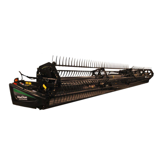
- Page 1 FD75 ® FlexDraper Combine Header IMPORTANT: PAGE 31 HAS BEEN UPDATED SINCE THIS MANUAL WAS PUBLISHED. Operator’s Manual 147695 Revision A 2016 Model Year Original Instruction Featuring MacDon FLEX-FLOAT Technology ™ The harvesting specialists.
- Page 2 ® FD75 FlexDraper Header for Combines Published: May 2015...
- Page 3 Declaration of Conformity 147695 Revision A...
- Page 4 147695 Revision A...
- Page 5 Keep this manual handy for frequent reference and to pass on to new Operators or Owners. A storage case for this manual is located inside the header left endshield. Call your MacDon Dealer if you need assistance, information, or additional copies of this manual. NOTE: Keep your MacDon publications up-to-date.
- Page 6 List of Revisions The following lists the changes from the previous version (169894 Revision A) of this document. Summary of Change Refer To ® • FD75 FlexDraper Header Operator’s Manual from New Book Part Number MD #196894_A to MD #147695_A •...
-
Page 7: Model And Serial Number
Model and Serial Number Record the model number, serial number, and model year of the header, combine adapter, and transport/stabilizer wheel option (if installed) on the lines below. NOTE: Right-hand (RH) and left-hand (LH) designations are determined from the operator’s position, facing forward. Draper Header Header Model: Serial Number:... -
Page 9: Table Of Contents
TABLE OF CONTENTS Declaration of Conformity ........................i Introduction ............................. iii List of Revisions ..........................iv Model and Serial Number......................... v Safety ..............................1 Safety Alert Symbols........................1 Signal Words........................... 2 General Safety ..........................3 Maintenance Safety ......................... 5 Hydraulic Safety ..........................6 Safety Signs ............................ - Page 10 TABLE OF CONTENTS Locking/Unlocking Header Wings..................64 Operating in Flex Mode ....................64 Operating in Rigid Mode....................65 3.7.3 Header Angle......................... 66 Controlling Header Angle ....................67 3.7.4 Reel Speed..........................67 Optional Reel Drive Sprockets ..................68 3.7.5 Ground Speed ........................68 3.7.6 Draper Speed ........................
- Page 11 TABLE OF CONTENTS 3.8.5 Gleaner R62/R72 Combines ....................114 Determining System Requirements (Gleaner R62/R72) ............ 114 Calibrating the Auto Header Height Control (Gleaner R62/R72) ........114 Setting the Sensitivity of the Auto Header Height Control (Gleaner R62/R72 Series) ... 114 3.8.6 Gleaner R65/R75 Combines ....................
- Page 12 TABLE OF CONTENTS 3.12 Upper Cross Auger (UCA) ......................177 3.12.1 Removing Beater Bars......................177 3.12.2 Installing Beater Bars ......................178 3.13 Transporting Header ........................179 3.13.1 Transporting Header on Combine...................179 3.13.2 Towing..........................179 Attaching Header to Towing Vehicle ................180 Towing the Header ......................180 3.13.3 Converting from Transport to Field Position................181 Removing Tow-Bar ......................181 Storing Tow-Bar ......................182...
- Page 13 TABLE OF CONTENTS 5.3.5 Checking Hydraulic Hoses and Lines..................259 5.3.6 Lubrication and Servicing.......................259 Service Intervals ......................260 Greasing Procedure.......................268 Lubricating Reel Drive Chain ..................269 Lubricating Auger Drive Chain ..................270 Lubricating Header Drive Gearbox ..................271 Hydraulics ............................273 5.4.1 Reservoir ..........................273 Checking Oil Level in Hydraulic Reservoir ...............273 Adding Oil ........................273 Changing Oil .........................274 5.4.2...
- Page 14 TABLE OF CONTENTS Installing Knife Drive Box Pulley..................315 Installing Knife Drive Box....................315 Changing Oil in Knife Drive Box ..................318 5.9.2 Knife Drive Belts ........................318 Removing Knife Drive Belt....................318 Installing Knife Drive Belts ....................319 Tensioning Knife Drive Belts ...................320 5.10 Adapter Feed Draper ........................322 5.10.1 Replacing Adapter Feed Draper .....................322 5.10.2...
- Page 15 TABLE OF CONTENTS 5.14.1 Replacing Reel Drive Sprocket....................372 Removing Drive Cover ....................372 Loosening Drive Chain ....................372 Removing Drive Sprocket ....................373 Installing Drive Sprocket....................373 Tightening Drive Chain ....................374 Installing Drive Cover .....................374 5.14.2 Replacing Double Reel U-Joint....................375 Removing Drive Cover ....................375 Removing Double Reel U-Joint ..................375 Installing Double Reel U-Joint..................376 Installing Drive Cover .....................377...
- Page 16 TABLE OF CONTENTS 6.2.1 Cutterbar Wearplate ......................409 6.2.2 Knifehead Shield ........................409 6.2.3 Stub Guard Conversion Kit ....................410 6.2.4 Vertical Knife Mounts......................410 Header............................411 6.3.1 Divider Latch Kit ........................411 6.3.2 Stabilizer Wheels ........................411 6.3.3 Rice Divider Rods .........................412 6.3.4 Stabilizer/Slow Speed Transport Wheels.................412 Crop Delivery ..........................413 6.4.1...
-
Page 17: Safety
1 Safety 1.1 Safety Alert Symbols This safety alert symbol indicates important safety messages in this manual and on safety signs on the header. This symbol means: • ATTENTION! • BECOME ALERT! • YOUR SAFETY IS INVOLVED! Carefully read follow safety message accompanying this symbol. -
Page 18: Signal Words
SAFETY 1.2 Signal Words Three signal words, DANGER, WARNING, and CAUTION, are used to alert you to hazardous situations. The appropriate signal word for each situation has been selected using the following guidelines: DANGER Indicates an imminently hazardous situation that, if not avoided, will result in death or serious injury. WARNING Indicates a potentially hazardous situation that, if not avoided, could result in death or serious injury. -
Page 19: General Safety
SAFETY 1.3 General Safety CAUTION The following are general farm safety precautions that should be part of your operating procedure for all types of machinery. Protect yourself. • When assembling, operating, and servicing machinery, wear all the protective clothing and personal safety devices that could be necessary for the job at hand. - Page 20 SAFETY • Wear close-fitting clothing and cover long hair. Never wear dangling items such as scarves or bracelets. • Keep all shields in place. Never alter or remove safety equipment. Make sure driveline guards can rotate independently of the shaft and can telescope freely. •...
-
Page 21: Maintenance Safety
SAFETY 1.4 Maintenance Safety To ensure your safety while maintaining the machine: • Review the operator’s manual and all safety items before operation and/or maintenance of the machine. • Place all controls in Neutral, stop the engine, set the park brake, remove the ignition key, and wait for all moving parts to stop before servicing, adjusting, and/or repairing. -
Page 22: Hydraulic Safety
SAFETY 1.5 Hydraulic Safety • Always place hydraulic controls Neutral before dismounting. • Make sure that all components in the hydraulic system are kept clean and in good condition. • Replace any worn, cut, abraded, flattened, or crimped hoses and steel lines. •... -
Page 23: Safety Signs
SAFETY 1.6 Safety Signs • Keep safety signs clean and legible at all times. • Replace safety signs that missing become illegible. • If original parts on which a safety sign was installed are replaced, be sure the repair part also bears the current safety sign. -
Page 24: Safety Decal Locations
SAFETY 1.7 Safety Decal Locations Figure 1.15: Upper Cross Auger A - MD #174682 Figure 1.16: Slow Speed Transport A - MD #220799 147695 Revision A... - Page 25 SAFETY Figure 1.17: Slow Speed Transport Tow-Bar A - MD #220797 B - MD #220798 Figure 1.18: Vertical Knife A - MD #174684 147695 Revision A...
- Page 26 SAFETY Figure 1.19: Endsheets, Reel Arms, Backsheet A - MD #131393 B - MD #174632 C - MD #184371 D - MD #184371 (DK Only) E - MD #131392 (2 Places) F - MD #131391 (2 Places) G - MD #174436 H - MD #184371 (DK 2 Places) 147695 Revision A...
- Page 27 SAFETY Figure 1.20: Backtube A - MD #184372 B - MD #166466 C - MD #131391 D - MD #131392 E - MD #184372 (Split Frame) 147695 Revision A...
-
Page 28: Understanding Safety Signs
SAFETY 1.8 Understanding Safety Signs MD #131391 Crushing hazard DANGER • Rest header on ground or engage safety props before going under unit. Figure 1.21: MD #131391 MD #131392 Crushing hazard WARNING • To avoid injury from fall of raised reel; fully raise reel, stop the engine, remove the key, and engage safety prop on each reel support arm before working on or under reel. - Page 29 SAFETY MD #166466 High pressure oil hazard WARNING • Do not go near leaks. • High pressure oil easily punctures skin causing serious injury, gangrene, or death. • If injured, seek emergency medical help. Immediate surgery is required to remove oil. •...
- Page 30 SAFETY MD #174434 Header hazard DANGER • Rest header on ground or engage mechanical locks before going under unit. Figure 1.27: MD #174434 MD #174436 High pressure oil hazard WARNING • Do not go near leaks • High pressure oil easily punctures skin causing serious injury, gangrene, or death.
- Page 31 SAFETY MD #174682 Auger entanglement hazard CAUTION • To avoid injury from entanglement with rotating auger, stand clear of header while machine is running. Figure 1.30: MD #174682 MD #174684 Sharp component hazard CAUTION • Wear heavy canvas or leather gloves when working with knife.
- Page 32 SAFETY MD #184372 General hazard pertaining machine operation and servicing CAUTION To avoid injury or death from improper or unsafe machine operation: • Read the operator’s manual and follow all safety instructions. If you do not have a manual, obtain one from your Dealer.
- Page 33 SAFETY MD #190546 Slippery surface WARNING • Do not use this area as a step or platform. • Failure to comply could result in serious injury or death. Figure 1.34: MD #190546 MD #193147 Transport/roading hazard WARNING • Ensure tow-bar lock mechanism is locked. Figure 1.35: MD #193147 147695 Revision A...
- Page 34 SAFETY MD #194521 Auger entanglement hazard CAUTION • To avoid injury from entanglement with rotating auger, stand clear of header/mower while machine is running. General hazard pertaining machine operation and servicing. CAUTION • Read the operator’s manual and follow safety instructions.
- Page 35 SAFETY MD #220798 Loss of control hazard in transport CAUTION • Do not tow the header with a dented or otherwise damaged tow pole (the circle with the red X shows a dent in the pole). • Consult the operator’s manual for more information. Figure 1.38: MD #220798 MD #220799 Transport/roading hazard...
-
Page 37: Product Overview
A hydraulic cylinder link between the header and the machine to which it is attached: Center-link It is used to change header angle CGVW Combined vehicle gross weight D-Series header MacDon’s D50, D60, and D65 rigid draper headers Double knife Double-knife drive Double-draper drive Double reel ®... - Page 38 PRODUCT OVERVIEW Term Definition An internally threaded fastener that is designed to be paired with a bolt National Pipe Thread: A style of fitting used for low pressure port openings Threads on NPT fittings are uniquely tapered for an interference fit O-ring boss: A style of fitting commonly used in port opening on manifolds, pumps, and motors O-ring face seal: A style of fitting commonly used for connecting hoses and tubes...
-
Page 39: Specifications
PRODUCT OVERVIEW 2.2 Specifications | FD75 | CA25 | Attachments S: standard / O : optional (factory installed) / O : optional (dealer installed) / -: not available Cutterbar Effective cutting width (distance between crop divider points) 30-ft. header 30 ft. (360 in. [9144 mm]) 35-ft. - Page 40 PRODUCT OVERVIEW Conveyor (Draper) and Decks Draper width 41-19/32 in. (1057 mm) Draper drive Hydraulic Draper speed: CA25 Combine Adapter controlled 0–464 fpm (141 m/min.) Delivery opening width 73-19/32 in. (1870 mm) PR15 Pick-Up Reel Quantity of tine tubes 5-, 6-, or 9-tine tubes Center tube diameter 8 in.
- Page 41 PRODUCT OVERVIEW Attachments CA25 Combine Adapter Width 78-11/16 in. (2000 mm) Feed draper 350–400 fpm Speed (107–122 m/min) Width 65-5/16 in. (1660 mm) Outside diameter 22 in. (559 mm) Feed auger Tube diameter 14 in. (356 mm) Speed (varies with 150 rpm combine model) 16 US Gallons...
-
Page 42: Component Identification
PRODUCT OVERVIEW 2.3 Component Identification ® 2.3.1 FD75 FlexDraper ® Figure 2.2: FD75 FlexDraper Components A - Wing Float Linkage B - Center-Link C - Center Reel Arm Prop Handle D - Transition Pan E - Reel Fore-Aft Cylinder F - Reel Lift Cylinder G - Endshield H - Knife Drive J - Crop Divider... -
Page 43: Ca25 Combine Adapter
PRODUCT OVERVIEW 2.3.2 CA25 Combine Adapter Figure 2.3: Header Side of CA25 Combine Adapter A - Feed Auger B - Header Float Springs C - Center-Link D - Hydraulic Reservoir E - Gearbox F - Header Support Arm G - Feed Draper 147695 Revision A... - Page 44 PRODUCT OVERVIEW Figure 2.4: Combine Side of CA25 Combine Adapter A - Adapter Gearbox B - Hydraulic Compartment Cover C - Reservoir Oil Level Sight Glass D - Center-Link E - Header Height Control Indicator F - Transition Frame G - Torque Wrench H - Header Float Lock J - Side Draper Speed Control 147695...
-
Page 45: Operation
• It is your responsibility to read and understand this manual completely before operating the header. Contact your MacDon Dealer if an instruction is not clear to you. • Follow all safety messages in the manual and on safety decals on the machine. -
Page 46: Operational Safety
OPERATION 3.2 Operational Safety CAUTION Follow these safety precautions: • Follow all safety and operational instructions given in your operator’s manuals. If you do not have a combine manual, get one from your Dealer and read it thoroughly. • Never attempt to start the engine or operate the machine except from the combine seat. -
Page 47: Reel Safety Props
OPERATION DANGER To avoid bodily injury or death from unexpected start-up or fall of raised machine, always stop engine, remove key, and engage safety props before going under header for any reason. 3.2.2 Reel Safety Props WARNING To avoid bodily injury from fall of raised reel, always engage reel safety props before going under raised reel for any reason. -
Page 48: Disengaging Reel Safety Props
OPERATION 3. At the center reel arm on double-reel headers, use handle (A) to move lock rod to inboard position (B), engaging pin (C) under prop. 4. Lower reel until safety props contact cylinder mounts on outer reel arms and pin at center arm. Figure 3.4: Center Arm Reel Prop Disengaging Reel Safety Props 1. -
Page 49: Endshields
OPERATION 3. Use handle move lock outboard position. Figure 3.6: Center Arm Safety Prop 3.2.3 Endshields A hinged, polyethylene endshield is fitted on each end of the header. Opening Endshields To open an endshield, follow these steps: 1. Remove lynch pin (A) and tool (B) from pin (C) at top rear of endshield. -
Page 50: Closing Endshields
OPERATION 2. Use tool (B) to unlock latch (A) at lower rear corner of endshield. 3. Lift shield at aft end to clear pin at top rear of endshield. 4. Swing shield out and away from header while maintaining forward pressure to prevent shield from slipping out of tab (C) at front of endsheet. -
Page 51: Removing Endshields
OPERATION 3. Push in shield to engage lower latch (A). 4. Use tool (B) to lock lower latch (A). Figure 3.11: Left-Hand Endshield 5. Replace tool (B) and lynch pin (A) on top pin (C). Figure 3.12: Left-Hand Endshield Pin Removing Endshields To remove an endshield, follow these steps: 1. -
Page 52: Installing Endshields
OPERATION Installing Endshields To install an endshield, follow these steps: 1. Position endshield on support (A) and align the hole in the endshield with stud (B) on the support. Figure 3.14: Left-Hand Endshield 2. Secure endshield to the support with acorn nut (A). 3. -
Page 53: Adjusting Endshields
OPERATION Adjusting Endshields Plastic endshields may expand or contract when subjected to large temperature changes. The position of the top pin and lower catch can be adjusted to compensate for dimensional changes. To adjust the endshield, perform the following: 1. Check gap ‘X’ between the front end of shield and header frame and compare to chart. -
Page 54: Linkage Covers
OPERATION 3.2.4 Linkage Covers Plastic covers that are attached to the header frame protect the header wing balance mechanism from debris and weather. Removing Linkage Covers To remove a linkage cover, follow these steps: 1. Remove screw (A) and lift outboard end of cover (B). Figure 3.18: Linkage Cover 2. -
Page 55: Installing Linkage Covers
OPERATION Installing Linkage Covers To install a linkage cover, follow these steps: 1. Position inboard end of cover (A) over linkage and behind indicator bar (B). 2. Lower cover until secure and against header tube. Figure 3.20: Linkage Cover 3. Install screw (A) to hold cover (B) in place. Figure 3.21: Linkage Cover 147695 Revision A... -
Page 56: Daily Start-Up Check
OPERATION 3.2.5 Daily Start-Up Check CAUTION • Clear the area of other persons, pets, etc. Keep children away from machinery. Walk around the machine to be sure no one is under, on, or close to it. • Wear close-fitting clothing and protective shoes with slip-resistant soles. -
Page 57: Break-In Period
OPERATION 3.3 Break-in Period NOTE: Until you become familiar with the sound and feel of your new header, be extra alert and attentive. After attaching the header to the combine for the first time, follow these steps: 1. Operate the machine with reel drapers and knife running slowly for five minutes, watching and listening FROM THE OPERATOR’S SEAT for binding or interfering parts. -
Page 58: Shutting Down The Machine
OPERATION 3.4 Shutting Down the Machine CAUTION To shut down and before leaving the combine seat for any reason, follow these steps: • Park on level ground if possible. • Lower the header fully. • Place all controls in NEUTRAL or PARK. •... -
Page 59: Cab Controls
OPERATION 3.5 Cab Controls CAUTION Be sure all bystanders are clear of machine before starting engine or engaging any header drives. Refer to your combine operator’s manual for identification of in-cab controls for: • Header engage/disengage control • Header height •... -
Page 60: Header Setup
3.6.1 Header Attachments Several attachments to improve performance of your FD75 header are available as options that can be installed by your MacDon Dealer. Refer to 6 Options and Attachments, page 407 in this manual for a description of each item. - Page 61 OPERATION 147695 Revision A...
- Page 62 OPERATION 147695 Revision A...
- Page 63 OPERATION 147695 Revision A...
-
Page 64: Optimizing Header For Straight Combining Canola
OPERATION 3.6.3 Optimizing Header for Straight Combining Canola Ripe canola can be straight combined, but most varieties are very susceptible to shelling and subsequent seed loss. This section provides recommended attachments, settings, and adjustments to optimize ® FD75 FlexDraper headers for straight combining canola. The optimization process includes the following modifications to the header: •... -
Page 65: Adjusting Feed Auger Springs
OPERATION Adjusting Feed Auger Springs The CA25 feed auger has an adjustable spring tensioning system that allows the auger to float on the crop instead of crushing and damaging it. The tension is set at factory setting and is adequate for most crop conditions. If necessary, adjust the auger tension springs as follows: 1. -
Page 66: Reel Settings
OPERATION 3.6.4 Reel Settings Table 3.3 FD75 Reel Settings Chart Cam Setting Number Reel Position Reel Finger Pattern (Finger Speed Gain) Number 1 (0) 6 or 7 2 (20%) 6 or 7 147695 Revision A... - Page 67 OPERATION Cam Setting Number Reel Position Reel Finger Pattern (Finger Speed Gain) Number 3 (30%) 3 or 4 4 (35%) 2 or 3 NOTE: • Adjust reel forward to get closer to ground when tilting header back. Fingers/tines will dig into ground at extreme reel forward positions, so adjust skid shoes or header angle to compensate.
-
Page 68: Header Operating Variables
OPERATION 3.7 Header Operating Variables Satisfactory function of the header in all situations requires making proper adjustments to suit various crops and conditions. Correct operation reduces crop loss and allows cutting of more acres. As well, proper adjustments and timely maintenance will increase the length of service you receive from the machine. - Page 69 OPERATION Adjusting Stabilizer/Slow Speed Transport Wheels The proper setting requires balancing the amount of header weight carried by the float and the stabilizer/slow speed transport wheels. Refer to 3.6.2 Header Settings, page 44 for recommended use in specific crops and crop conditions. DANGER To avoid bodily injury or death from unexpected start-up of machine, always stop engine and remove key from ignition before leaving operator’s seat for any reason.
- Page 70 OPERATION 12. Lower header to desired cutting height using combine controls and check load indicator. As an example the image shows that the wheels are set to a range between ‘2’ and ‘3’ on load indicator. Figure 3.26: Load Indicator IMPORTANT: Continuous operation with excessive spring compression (i.e., load indicator reading greater than...
- Page 71 OPERATION 2. Support wheel weight by lifting slightly with one hand on handle (B). Pull up on handle (A) to release lock. 3. Lift wheel with handle (B) and engage support channel into center slot (C) in upper support. 4. Push down on handle (A) to lock. Figure 3.28: Stabilizer Wheel 5.
-
Page 72: Cutting On The Ground
OPERATION Cutting On the Ground Cutting on the ground is performed with the header fully lowered so that the cutterbar is on the ground. The orientation of the knife and knife guards relative to the ground (or header angle) is controlled with the skid shoes and center-link, and NOT with the header lift cylinders. - Page 73 OPERATION 6. Reinsert pin (B), engage in frame, and secure with lynch pin (A). 7. Check that all of the skid shoes are adjusted to the same position. 8. Adjust header angle to desired working position using the machine’s header angle controls. If angle is not critical, set it to mid-position.
-
Page 74: Header Float
OPERATION 3.7.2 Header Float The header float system reduces the ground pressure at the cutterbar and allows it to more easily follow the ground and quickly respond to sudden ground contour changes or obstacles. Header float is indicated on the CA25 float indicator (A) and the values 0 to 4 represent the force of the cutterbar on the ground, with ‘0’... - Page 75 OPERATION 1. Park combine on level surface. 2. Fully lower the reel and adjust the fore-aft position to between five and six on the position indicator decal (A) at the right side reel arm. Figure 3.36: Fore-Aft Position 3. Adjust the center-link to a position between ‘B’ and ‘C’ on the indicator (A).
- Page 76 OPERATION 7. Place wing lock spring handles lock (upper) position. Figure 3.38: Wing Lock in Lock Position 8. Move both header float lock levers down (UNLOCK). Figure 3.39: Header Float Lock in UNLOCK Position 9. Place stabilizer wheels and slow speed transport wheels (if equipped) in storage position as follows: a.
- Page 77 OPERATION 10. Remove supplied torque wrench (A) from storage position at right-hand side of adapter frame. Pull slightly in direction shown to disengage wrench from hook. Figure 3.41: Torque Wrench 11. Place supplied torque wrench (A) onto float lock at (B). Note position of wrench for checking right- or left-hand side.
- Page 78 3.7.1 Cutting Height, page 52 for details. NOTE: If adequate header float cannot be achieved using all of the available adjustments, an optional heavy duty spring is available. See your MacDon Dealer or refer to the parts catalog for ordering information. 147695 Revision A...
-
Page 79: Locking/Unlocking Header Float
OPERATION 18. Return torque wrench (A) to storage location at right-hand side of adapter frame. Figure 3.46: Torque Wrench Locking/Unlocking Header Float The function of the header float locks is to lock and unlock the header float system. There are two locks—one on each side of the adapter. -
Page 80: Locking/Unlocking Header Wings
OPERATION Locking/Unlocking Header Wings The FD75 is designed to operate with the cutterbar on the ground. The three sections move independently to follow the ground contours. In this mode, each wing is unlocked and is free to move up and down. The FD75 can also be operated as a rigid header with the cutterbar straight. -
Page 81: Operating In Rigid Mode
OPERATION 5. Place the torque wrench (A) on bolt (B) and use it to move the wing until the lock disengages. 6. Replace the torque wrench (A) and reinstall the linkage cover. 7. The wings should now freely move up and down with equal hand force and the cutterbar should be straight. -
Page 82: Header Angle
OPERATION 5. Place the torque wrench (A) on bolt (B) and use it to move the wing until the lock engages. 6. Replace the torque wrench (A) and reinstall the linkage cover. 7. The wings will not move relative to the header. Figure 3.53: Header Wing 3.7.3 Header Angle Header angle is the angle between the drapers and the ground, and is adjustable to accommodate crop conditions... -
Page 83: Controlling Header Angle
OPERATION Controlling Header Angle The header/guard angle is changed by adjusting the length of the center-link between the combine adapter and the header. The header/guard angle is controlled from the combine cab with a switch on the operator’s control console, and an indicator on the center-link. -
Page 84: Optional Reel Drive Sprockets
Refer to the following table and contact your MacDon Dealer for ordering information. -
Page 85: Draper Speed
OPERATION Figure 3.57: Ground Speed vs Acres A - 30 ft. B - 35 ft. C - 40 ft. Example shown above: At a ground speed of 6 miles per hour (9.7 km/h) with a 40 ft. header, the area cut in one hour would be approximately 28 acres (11.3 hectares). -
Page 86: Adjusting Side Draper Speed
3.6.3 Optimizing Header for Straight Combining Canola, page 48 NOTE: Insufficient draper speed may be caused by low relief pressure. See your MacDon Dealer for checking and adjusting relief pressure in the CA25 hydraulics. Figure 3.59: Flow Control Valve 147695... -
Page 87: Adjusting Feed Draper Speed
OPERATION Adjusting Feed Draper Speed The feed draper moves the cut crop from the side drapers into the adapter feed auger. The adapter feed draper (A) is driven by a hydraulic motor from a pump which is powered by the combine feeder house drive through a gearbox on the adapter. -
Page 88: Checking Knife Speed
6. Compare measured pulley rpm with the values in the knife speed chart. Refer to 3.7.7 Knife Speed, page 7. If it is higher than the specified range for your header, contact your MacDon dealer. Figure 3.62: Knife Drive Pulley 147695 Revision A... -
Page 89: Reel Height
OPERATION 3.7.8 Reel Height The crop type and condition determine the operating height of the reel. Set reel height to carry material past the knife onto the drapers with minimal disturbance and damage to the cut crop. Also refer to 3.7.9 Reel Fore-Aft Position, page The reel height is controlled with switches in the cab. -
Page 90: Adjusting Reel Fore-Aft Position
OPERATION A decal (A) is provided on the reel right support arm for identifying reel position. The cam disc aft edge (B) is the gauge indicator. For straight standing crop, center the reel over the cutterbar (4–5 on decal). For crops that are down, tangled, or leaning, it may be necessary to move the reel ahead of the cutterbar (lower number on decal). -
Page 91: Repositioning Fore-Aft Cylinders
OPERATION Repositioning Fore-Aft Cylinders The reel can be moved approximately 9 in. (227 mm) further aft by repositioning the fore-aft cylinders on the reel arms. This may be desirable when straight-combining canola. If the Multi-Crop Rapid Reel Conversion option is installed, refer to 3.7.10 Repositioning Fore-Aft Cylinders with Multi-Crop Rapid Reel Conversion Option, page To reposition the cylinders on a double reel, follow these steps:... - Page 92 OPERATION Reposition right arm cylinder as follows: NOTE: Reel components are not shown for clarity. 6. Remove four bolts (A) securing cylinder bracket (B) to reel arm. 7. Push reel back until bracket (B) lines up with the aft set of holes (C).
- Page 93 OPERATION Reposition left arm cylinder as follows: NOTE: Reel components are not shown for clarity. 9. Remove pin (A) securing cylinder (B) to bracket/light assembly (C). 10. Remove bolts (D) securing bracket (C) to reel arm and remove bracket/light assembly. 11.
-
Page 94: Repositioning Fore-Aft Cylinders With Multi-Crop Rapid Reel Conversion Option
OPERATION 3.7.10 Repositioning Fore-Aft Cylinders with Multi-Crop Rapid Reel Conversion Option The reel can be moved approximately 9 in. (227 mm) further aft by repositioning the fore-aft cylinders on the reel arms. The Multi-Crop Conversion option is applicable to double-reel headers only. WARNING Stop combine engine and remove key before making adjustments to machine. - Page 95 OPERATION Reposition center arm cylinder as follows: NOTE: Reel components are not shown for clarity. 6. Remove cotter pin (A) and remove clevis pin (B). 7. Push reel back until cylinder rod (C) lines up with the aft hole in brackets (D). 8.
-
Page 96: Reel Tine Pitch
OPERATION Figure 3.75: Aft Position – Right Arm 3.7.11 Reel Tine Pitch The pick-up reel is designed to pick up flattened and severely lodged crops. It is not always necessary to increase the tine pitch (higher cam setting) to pick up crops that are lodged, but rather, the cam settings are mainly used to determine how the crop will get delivered to the drapers. - Page 97 OPERATION Cam Position 2, Reel Position 3 or 4 is the recommended starting position for most crops and conditions. • This setting gives a fingertip speed approximately 20% faster than the reel speed. • If crops tend to stall on the cutterbar with the reel in a forward position, the cam setting should be increased to push the crop past the rear edge of the cutterbar.
-
Page 98: Adjusting Reel Cam
OPERATION Cam Position 4, Header Angle At Maximum, and Reel Fully Forward provides the maximum amount of reel reach below the cutterbar to pick up lodged crops and gives a finger tip speed approximately 35% faster than the reel speed. •... -
Page 99: Crop Dividers
OPERATION 3.7.12 Crop Dividers Crop dividers are used to help divide the crop when harvesting. They are removable to allow installation of vertical knives and to decrease transport width. Removing Crop Dividers from Header with Latch Option To remove crop dividers from a header with the latch option, follow these steps: DANGER To avoid bodily injury or death from unexpected start-up or fall of raised machine, always stop engine, remove key, and engage safety props before going under header for any reason. -
Page 100: Removing Crop Dividers From Header Without Latch Option
OPERATION Removing Crop Dividers from Header without Latch Option To remove crop dividers from a header without the latch option, follow these steps: DANGER To avoid bodily injury or death from unexpected start-up or fall of raised machine, always stop engine, remove key, and engage safety props before going under header for any reason. - Page 101 OPERATION 3. At divider storage location, lift divider to disengage lugs (A) at lower end and then lower it slightly to disengage pin (B) from endsheet. Figure 3.85: Stored Crop Divider 4. Position crop divider as shown by locating lugs (A) in holes in endsheet.
-
Page 102: Installing Crop Dividers On Header Without Latch Option
OPERATION 7. Check that divider does NOT move laterally. Adjust bolts (A) as required to tighten divider and remove lateral play when pulling at divider tip. 8. Close/install endshields. Figure 3.87: Crop Divider Installing Crop Dividers on Header without Latch Option To install crop dividers on a header without the latch option, follow these steps: DANGER To avoid bodily injury or death from unexpected start-up or fall of raised machine, always stop engine,... -
Page 103: Crop Divider Rods
OPERATION 5. Lift forward end of divider and install bolt (A) and special stepped washer (B) (step towards divider). Tighten bolt. 6. Check that divider does not move laterally. Adjust bolts (C) as required to tighten divider and remove lateral play when pulling at divider tip. 7. -
Page 104: Removing Crop Divider Rods
OPERATION Removing Crop Divider Rods To remove divider rods, follow these steps: 1. Loosen bolt (B) and remove rod (A). Figure 3.90: Crop Divider Rod 2. Store both rods on the inboard side of the right endsheet. Figure 3.91: Stored Divider Rod Rice Dividers Optional special rice dividers can be installed and used when required. -
Page 105: Auto Header Height Control (Ahhc)
OPERATION 3.8 Auto Header Height Control (AHHC) MacDon’s Auto Header Height Control (AHHC) feature works in conjunction with the AHHC option available on certain combine models. A sensor is installed in the float indicator box (A) on the CA25 Combine Adapter. This sensor send a signal to the combine allowing it to maintain a consistent cutting height and an optimum adapter float as the header follows... - Page 106 OPERATION NOTE: If your CA25 Combine Adapter is not equipped to work with a specific combine model, you will need to install the appropriate combine completion package. Completion packages come with instructions for installing the AHHC sensor on the combine adapter. Refer to the following instructions for your specific combine model: •...
-
Page 107: Auto Header Height Control Sensor Output Voltage Range - Combine Requirements
OPERATION 3.8.1 Auto Header Height Control Sensor Output Voltage Range – Combine Requirements The Auto Header Height Control (AHHC) sensor output must be within a specific voltage range for each combine, or the AHHC feature will not work properly. Table 3.10 Combine Voltage Limits Range (Difference Combine Low Voltage Limit... - Page 108 OPERATION 3. Adjust the cable take-up bracket (B) (if necessary) until the pointer (A) on the float indicator is on ‘0’. Figure 3.95: Float Indicator Box (Most Common 5 Volt AHHC Sensor Assembly Shown) 4. Using a voltmeter (A), measure the voltage between the ground (Pin 2) and signal (Pin 3) wires at the AHHC sensor in the float indicator box.
-
Page 109: Adjusting Voltage Limits
OPERATION Adjusting Voltage Limits NOTE: The Auto Header Height Control (AHHC) sensor assemblies used for Lexion and some New Holland combines are slightly different from the sensor assemblies used for other combine models—all three assemblies are illustrated in this procedure. 1. -
Page 110: Challenger 6 And 7 Series Combines
OPERATION Figure 3.100: Most Common 5 Volt AHHC Sensor Assembly 3.8.2 Challenger 6 and 7 Series Combines Checking Voltage Range from the Combine Cab (Challenger 6 and 7 Series) NOTE: Changes may have been made to the combine controls or display since this document was published. Refer to the combine operator’s manual for updates. - Page 111 OPERATION 3. Adjust the cable take-up bracket (B) (if necessary) until the pointer (A) on the float indicator is on ‘0’. Figure 3.102: Float Indicator Box 4. Go to the FIELD page on the combine monitor, and then press the diagnostics icon. MISCELLANEOUS page displays.
-
Page 112: Engaging The Auto Header Height Control (Challenger 6 Series)
OPERATION 7. Fully lower the combine feeder house adapter should be fully separated from the header). NOTE: You may need to hold the header down switch for a few seconds to ensure the feeder house is fully lowered. 8. Read voltage. 9. -
Page 113: Calibrating The Auto Header Height Control (Challenger 6 Series)
OPERATION Calibrating the Auto Header Height Control (Challenger 6 Series) NOTE: For best performance of the Auto Header Height Control (AHHC) system, perform these procedures with the center-link set to D. When setup and calibration are complete, adjust the center-link back to desired header angle. Refer to 3.7.3 Header Angle, page NOTE:... - Page 114 OPERATION 4. Press HEADER button. The HEADER CALIBRATION page displays a warning. Figure 3.109: Challenger Combine Display 5. Read the warning message, and then press the green check mark button. Figure 3.110: Challenger Combine Display 6. Follow the on-screen prompts to complete calibration. NOTE: The calibration procedure can be cancelled at anytime by pressing the cancel button in the...
-
Page 115: Adjusting The Header Height (Challenger 6 Series)
OPERATION Adjusting the Header Height (Challenger 6 Series) Once the Auto Header Height Control (AHHC) is activated, press and release the header lower button on the control handle. The AHHC will automatically lower the header to the selected height setting. NOTE: Changes may have been made to the combine controls or display since this document was published. -
Page 116: Setting The Sensitivity Of The Auto Header Height Control (Challenger 6 Series)
OPERATION 2. Press HEADER CONTROL (A). The HEADER CONTROL page displays. Figure 3.114: Challenger Combine Display 3. Go to the TABLE SETTINGS tab. 4. Press up arrow on MAX UP PWM to increase percentage number and increase raise speed; Press down arrow on MAX UP PWM to decrease percentage number and decrease raise speed. -
Page 117: Case Ih 2300/2500 And 5088/6088/7088 Combines
OPERATION 2. Press the HEADER CONTROL button (A). The HEADER CONTROL page appears. You can adjust sensitivity on this page using the up and down arrows. Figure 3.116: Challenger Combine Display 3. Adjust the sensitivity to the maximum setting. 4. Activate the AHHC, and press the header lower button on the control handle. - Page 118 OPERATION 1. Turn mode select switch (A) to HT. 2. Set the desired header height with position control knob (B). The AHHC will raise and lower the header to maintain this fixed distance from the ground. 3. Turn feeder ON. 4.
-
Page 119: Calibrating The Auto Header Height Control (Case Ih 2300/2500 And 5088/6088/7088)
OPERATION Calibrating the Auto Header Height Control (Case IH 2300/2500 and 5088/6088/7088) For best performance of the Auto Header Height Control (AHHC) system, perform ground calibration with center-link set to D. When calibration is complete, adjust the center-link back to desired header angle. Refer to 3.7.3 Header Angle, page NOTE: Changes may have been made to the combine controls or display since this document was published. -
Page 120: Setting The Sensitivity Of The Auto Header Height (Case Ih 2300/2500 And 5088/6088/7088)
OPERATION Figure 3.123: Joystick Lever (Case IH 5088/6088/7088) Setting the Sensitivity of the Auto Header Height (Case IH 2300/2500 and 5088/6088/7088) The sensitivity adjustment controls the distance the cutterbar must travel up or down before the Auto Header Height Control (AHHC) reacts and raises or lowers the feeder house. When the sensitivity is set to maximum, only small changes in ground height are needed to cause the feeder house to raise or lower. -
Page 121: Case Ih 5130/6130/7130, 7010/8010, 7120/8120/9120, And 7230/8230/9230 Combines
OPERATION Figure 3.125: Height Sensitivity Change Screen 3.8.4 Case IH 5130/6130/7130, 7010/8010, 7120/8120/9120, and 7230/8230/9230 Combines Checking Voltage Range from the Combine Cab (Case 8010) NOTE: Changes may have been made to the combine controls or display since this document was published. Refer to the combine operator’s manual for updates. - Page 122 OPERATION 3. Adjust the cable take-up bracket (B) (if necessary) until the pointer (A) on the float indicator is on ‘0’. Figure 3.127: Float Indicator Box 4. Ensure header float is unlocked. 5. Select DIAG (A) on the Universal display MAIN screen. The DIAG screen opens.
- Page 123 OPERATION 7. Select HEIGHT/TILT (A). SENSOR window opens. Figure 3.130: Case 8010 Combine Display 8. Select LEFT SEN (A). The exact voltage is displayed. Raise and lower the header to see the full range of voltage readings. Figure 3.131: Case 8010 Combine Display 9.
-
Page 124: Checking Voltage Range From The Combine Cab (Case Ih 5130/6130/7130, 7010/8010; 7120/8120/9120; 7230/8230/9230)
OPERATION Checking Voltage Range from the Combine Cab (Case IH 5130/6130/7130, 7010/8010; 7120/8120/9120; 7230/8230/9230) NOTE: Changes may have been made to the combine controls or display since this document was published. Refer to the combine operator’s manual for updates. To check the sensor output voltage range from the combine cab for Pro 600 Display, follow these steps: 1. - Page 125 OPERATION 4. Ensure header float is unlocked. 5. Select DIAGNOSTICS (A) on the MAIN screen. The DIAGNOSTICS screen opens. 6. Select SETTINGS. The SETTINGS screen displays. Figure 3.135: Case IH Combine Display 7. Select GROUP arrow (A). GROUP window opens. Figure 3.136: Case IH Combine Display 8.
-
Page 126: Calibrating The Auto Header Height Control (Case Ih 5130/6130/7130, 7010/8010; 7120/8120/9120; 7230/8230/9230)
OPERATION 9. Select LEFT HEADER HEIGHT SEN (A), and then select the GRAPH button (B). The exact voltage is displayed at top of screen. Raise and lower the header to see the full range of voltage readings. 10. Adjust the voltage limits (refer to Adjusting Voltage Limits, page 93) if the sensor voltage is not within the... - Page 127 OPERATION 1. Ensure center-link is set to D. 2. Ensure all header and adapter electrical and hydraulic connections are made. 3. Select TOOLBOX on the MAIN screen, and then select HEADER. 4. Set appropriate HEADER STYLE. Figure 3.140: Case IH Combine Display 5.
-
Page 128: Calibrating The Auto Header Height Control System (Case Combines With Version 28.00 Software)
OPERATION 9. Install FORE-AFT CONTROL, and HDR FORE-AFT TILT (if applicable). Figure 3.143: Case IH Combine Display 10. Press HEAD2 at bottom of screen. 11. Ensure HEADER TYPE is DRAPER. NOTE: If recognition resistor is plugged in to header harness, you will not be able to change this. 12. - Page 129 OPERATION 2. Select TOOLBOX on the MAIN screen, and then select HEADER SETUP. 3. Locate the HEADER SUB TYPE field. It will be located on either the HEAD 1 or the HEAD 2 tab. 4. Select 2000 (A). Figure 3.145: Combine Display 5.
-
Page 130: Gleaner R62/R72 Combines
OPERATION 3.8.5 Gleaner R62/R72 Combines Determining System Requirements (Gleaner R62/R72) NOTE: Changes may have been made to the combine controls or display since this document was published. Refer to the combine operator’s manual for updates. The following system components are required in order for the Auto Header Height Control (AHHC) system to work: •... - Page 131 OPERATION 1. Engage the Main Threshing Clutch (A) and Header Clutch (B). Figure 3.149: Combine Control Console 2. Speed the throttle (A) to over 2000 rpm. Figure 3.150: Throttle 147695 Revision A...
- Page 132 OPERATION 3. Push the AUTO HEADER HEIGHT button (A). The LED light (B) should flash continuously indicating that it is in standby mode and waiting for a response from the operator. Figure 3.151: Combine Header Control System 4. Briefly press the header down button (A). The header should lower automatically and the LED light should stay illuminated indicating that the auto height system is engaged and working.
-
Page 133: Gleaner R65/R75 Combines
OPERATION 3.8.6 Gleaner R65/R75 Combines Checking Voltage Range from the Combine Cab (Gleaner R65/R75) NOTE: Changes may have been made to the combine controls or display since this document was published. Refer to the combine operator’s manual for updates. To check the sensors output voltage range from the combine cab, follow these steps: 1. -
Page 134: Engaging The Auto Header Height Control (Gleaner R65/R75)
OPERATION Figure 3.156: Combine Heads Up Display Engaging the Auto Header Height Control (Gleaner R65/R75) NOTE: Changes may have been made to the combine controls or display since this document was published. Refer to the combine operator’s manual for updates. The following system components are required in order for the Auto Header Height Control (AHHC) to work: •... - Page 135 OPERATION Figure 3.157: Combine AHHCs 1. Press the AUTO MODE (A) button until the AHHC LED light (B) begins flashing. If the RTC light is flashing, press the AUTO MODE (A) button again until it switches to AHHC. 2. Briefly press button (A) on the control handle. The AHHC light should change from flashing to solid.
-
Page 136: Calibrating The Auto Header Height Control (Gleaner R65/R75)
The engine rpm also must be above 2000 rpm. The Header Tilt option on 2004 and earlier model combines does not work with MacDon headers. This system will have to be removed and disabled in order to calibrate the Auto Header Height Control (AHHC). -
Page 137: Turning The Accumulator Off (Gleaner R65/R75)
OPERATION 5. Press CAL2 button (G) until lower header light (E) stops flashing, and release it when the raise header light (D) begins flashing. 6. Raise header to its maximum height (ensure the header is resting on the down-stop pads). 7. -
Page 138: Adjusting The Header Raise/Lower Rate (Gleaner R65/R75)
OPERATION Adjusting the Header Raise/Lower Rate (Gleaner R65/R75) NOTE: Changes may have been made to the combine controls or display since this document was published. Refer to the combine operator’s manual for updates. The Auto Header Height Control (AHHC) system’s stability is affected by hydraulic flow rates. -
Page 139: Adjusting The Sensitivity Of The Auto Header Height Control (Gleaner R65/R75)
OPERATION To adjust header height, ensure the header is in Auto Header Height Control (AHHC) mode. This is indicated by the AUTO MODE LED light (A) displaying a continuous, solid light. The header will lower to the height (ground pressure) corresponding to the position selected with the height control knob (B). -
Page 140: Troubleshooting Alarms And Diagnostic Faults (Gleaner R65/R75)
OPERATION Figure 3.164: Auto Header Height Control (AHHC) Console The sensitivity adjustment dial (A) controls the distance the cutterbar must travel up or down before the AHHC reacts and raises or lowers the feeder house. When the sensitivity adjustment dial (A) is set to maximum (turned completely clockwise), only small changes in ground height are needed to cause the feeder house to raise or lower. - Page 141 OPERATION Display type: Displayed on tachometer (A) as ‘XX’ or ‘XXX’. Figure 3.165: Tachometer Displayed on LCD (A) as ‘XX in.’ or ‘XXX cm’. Figure 3.166: Combine LCD Display 147695 Revision A...
- Page 142 OPERATION Alarm conditions: If an error is indicated in message received from the fuse panel, an audible alarm sounds. The LCD on the EIP indicates the header system in error as HDR CTRL followed by HGT ERR for height, and HDR CTRL followed by TILT ERR for tilt.
-
Page 143: John Deere 50 Series Combines
OPERATION 3.8.7 John Deere 50 Series Combines Checking Voltage Range from the Combine Cab (John Deere 50 Series) NOTE: Changes may have been made to the combine controls or display since this document was published. Refer to the combine operator’s manual for updates. To check the sensor output voltage range from the combine cab, follow these steps: 1. - Page 144 OPERATION Figure 3.169: Combine HHS Monitor 4. Press the DIAGNOSTIC button (D) on the monitor – DIA appears on the monitor. 5. Press the UP button (A) until EO1 appears on the monitor – this is the header adjustments. 6. Press the ENTER button (C). 7.
-
Page 145: Calibrating The Auto Header Height Control (John Deere 50 Series)
OPERATION Calibrating the Auto Header Height Control (John Deere 50 Series) For best performance of the Auto Header Height Control (AHHC), perform these procedures with the center-link set to D. When setup and calibration are complete, adjust the center-link back to desired header angle. Refer to 3.7.3 Header Angle, page NOTE: Changes may have been made to the combine controls or display since this document was published. - Page 146 OPERATION 7. Press the UP or DOWN buttons until hdr appears on the monitor. 8. Press the enter button – HDR H-DN appears on the monitor. Figure 3.171: Combine Display 9. Fully lower feeder house to the ground. NOTE: You may need to hold the header down switch for a few seconds to ensure the feeder house is fully lowered.
-
Page 147: John Deere 60 Series Combines
OPERATION 3.8.8 John Deere 60 Series Combines Checking Voltage Range from the Combine Cab (John Deere 60 Series) NOTE: Changes may have been made to the combine controls or display since this document was published. Refer to the combine operator’s manual for updates. To check the sensor output voltage range from the combine cab, follow these steps: 1. -
Page 148: Calibrating The Auto Header Height Control (John Deere 60 Series)
OPERATION Figure 3.175: Combine HHS Monitor 4. Adjust the voltage limits (refer to Adjusting Voltage Limits, page 93) if the sensor voltage is not within the low and high limits or if the range between the low and high limits is insufficient (refer to Table 3.10 Combine Voltage Limits, page 91). - Page 149 OPERATION 5. Press the DIAGNOSTIC button (A) on the monitor – DIA appears on the monitor. 6. Press the CAL button (B) – DIA-CAL appears on the monitor. Figure 3.176: Combine Display 7. Press the UP or DOWN buttons until HDR appears on the monitor.
-
Page 150: Turning The Accumulator Off (John Deere 60 Series)
OPERATION 10. Press the CAL button (A) to save the calibration of the header – HDR H-UP appears on the monitor. 11. Raise the header three feet off the ground and press the CAL (A) button – EOC appears on the monitor. 12. -
Page 151: Setting The Sensitivity Of The Auto Header Height Control (John Deere 60 Series)
NOTE: Do NOT use the active header float function (A) in combination with the MacDon Auto Header Height Control (AHHC) – the two systems will counteract one another. The header symbol (B) on the display should NOT have a wavy line under it and should... -
Page 152: Adjusting The Threshold For The Drop Rate Valve (John Deere 60 Series)
OPERATION 1. Press the DIAGNOSTIC button (A) on the monitor – DIA appears on the monitor. 2. Press the UP button (B) until EO1 appears on the monitor, and press ENTER (D) – this is the header adjustment. 3. Press the UP (B) or DOWN (C) button until ‘112’... -
Page 153: John Deere 70 Series Combines
OPERATION 1. Press the DIAGNOSTIC button (A) on the monitor – DIA appears on the monitor. 2. Press the UP button (B) until EO1 appears on the monitor and press ENTER (C) – this is the header adjustment. 3. Press the UP (B) or DOWN button until ‘114’ is displayed on the top portion of the monitor –... - Page 154 OPERATION 2. Check that float lock linkage is on down stops (washer [A] and nut [B] cannot be moved) at both locations. NOTE: If the header is not on down stops during the next two steps, the voltage may go out of range during operation causing a malfunction of the AHHC system.
- Page 155 OPERATION 5. Ensure the three icons (A) depicted in the illustration at right appear on the monitor. Figure 3.187: Combine Display 6. Use scroll knob (A) to highlight the middle icon (the green ‘i’) and press the check mark button (B) to select it.
- Page 156 OPERATION 9. Use the scroll knob to highlight LC 1.001 VEHICLE (A) is highlighted and press the check mark button to select it. Figure 3.190: Combine Display 10. Use the scroll knob to highlight the DOWN ARROW (A) and press the check mark button to scroll through the list until 029 DATA (B) is displayed and voltage reading (C) appears on the monitor.
-
Page 157: Calibrating Feeder House Speed (John Deere 70 Series)
OPERATION Calibrating Feeder House Speed (John Deere 70 Series) The feeder house speed must be calibrated before you calibrate the Auto Header Height Control (AHHC) system. Refer to the combine operator’s manual for instructions. Calibrating the Auto Header Height Control (John Deere 70 Series) For best performance of the Auto Header Height Control (AHHC), perform these procedures with the center-link set to D. -
Page 158: Setting The Sensitivity Of The Auto Header Height Control (John Deere 70 Series)
OPERATION Setting the Sensitivity of the Auto Header Height Control (John Deere 70 Series) NOTE: Changes may have been made to the combine controls or display since this document was published. Refer to the combine operator’s manual for updates. 1. Press button (A) twice and the current sensitivity setting will appear on the monitor (the lower the reading, the lower the sensitivity). -
Page 159: John Deere S Series Combines
OPERATION 1. Press button (A) and the current raise/lower rate setting will appear on the monitor (the lower the reading, the slower the rate). 2. Use scroll knob (B) to adjust the rate. The adjustment will be saved automatically. NOTE: If the page remains idle for a short period of time, it will automatically return to the previous page. - Page 160 OPERATION 2. Check that float lock linkage is on down stops (washer [A] and nut [B] cannot be moved) at both locations. NOTE: If the header is not on down stops during the next two steps, the voltage may go out of range during operation causing a malfunction of the AHHC system.
- Page 161 OPERATION 5. Press DIAGNOSTIC READINGS icon on the CALIBRATION page. The DIAGNOSTIC READINGS page appears. This page provides access to calibrations, header options, and diagnostic information. Figure 3.201: Combine Display 6. Select AHHC RESUME (A) and a list of calibration options appears.
-
Page 162: Calibrating The Auto Header Height Control (John Deere S Series)
• CENTER HEADER HEIGHT • RIGHT HEADER HEIGHT A reading is displayed for only the center header height sensor. On the MacDon header, there is only one sensor located in the float indicator box on top of the CA25. Figure 3.204: Combine Display 10. - Page 163 OPERATION 4. Press the DIAGNOSTIC icon (A) on the main page of the monitor. The CALIBRATION page appears. Figure 3.205: Combine Display 5. Select THRESHING CLEARANCE (A) and a list of calibration options appears. Figure 3.206: Combine Display 6. Select FEEDER HOUSE SPEED (A) and calibrate. 7.
-
Page 164: Setting The Sensitivity Of The Auto Header Height Control (John Deere S Series)
OPERATION 8. Press icon (A) with either FEEDER HOUSE SPEED or HEADER selected and the icon will turn green. Figure 3.208: Combine Display 9. Click button (A) and instructions will appear on screen to guide you through the remaining calibration steps. NOTE: If an error code appears during calibration, the sensor is out of voltage range and will require... -
Page 165: Adjusting The Manual Header Raise/Lower Rate (John Deere S Series)
OPERATION 2. Press the ‘-’ or ‘+’ icon (A) to adjust rates. NOTE: The numbers depicted on the displays in these illustrations are for reference purposes only; they are not intended to represent the specific settings for your equipment. Figure 3.211: Combine Display Adjusting the Manual Header Raise/Lower Rate (John Deere S Series) NOTE: Changes may have been made to the combine controls or display since this document was published. -
Page 166: Lexion 500 Series Combines
OPERATION 3.8.11 Lexion 500 Series Combines Calibrating the Auto Header Height Control (Lexion 500 Series) For best performance of the Auto Header Height Control (AHHC), perform these procedures with the center-link set to D. When setup and calibration are complete, adjust the center-link back to desired header angle. Refer to 3.7.3 Header Angle, page NOTE: Changes may have been made to the combine controls or display since this document was published. - Page 167 OPERATION 5. Use the ‘<’ or ‘>’ key to select CUTT.HEIGHT LIMITS, and press the OK key (C). 6. Follow the procedure displayed on the screen to program the upper and lower limits of the header into the CEBIS. Figure 3.216: Combine Display 7.
-
Page 168: Setting Cutting Height (Lexion 500 Series)
OPERATION Setting Cutting Height (Lexion 500 Series) Cutting heights can be programmed into the preset cutting height and auto contour systems. Use the preset cutting height system for cutting heights above 5.9 in. (150 mm), and use the auto contour system for cutting heights below 5.9 in. - Page 169 OPERATION 8. Briefly press button (A) or button (B) in order to select the set point. 9. Repeat Step 7., page 152 for the set point. Figure 3.221: Joystick Buttons Setting Cutting Height Manually (Lexion 500 Series) NOTE: Changes may have been made to the combine controls or display since this document was published. Refer to the combine operator’s manual for updates.
- Page 170 OPERATION NOTE: Changes may have been made to the combine controls or display since this document was published. Refer to the combine operator’s manual for updates. 1. Use the ‘<’ key (C) or the ‘>’ key (D) to select SENSITIVITY CAC, and press the OK key (E). 2.
- Page 171 OPERATION Figure 3.225: Flow Chart for Setting the Sensitivity of the Float Optimizer 147695 Revision A...
- Page 172 OPERATION Adjusting Auto Reel Speed (Lexion 700 Series) NOTE: Changes may have been made to the combine controls or display since this document was published. Refer to the combine operator’s manual for updates. 1. Use control knob (A) to highlight the HEADER/REEL icon (B), and press control knob (A) to select it.
-
Page 173: Lexion 700 Series Combines
OPERATION 3. Select ACTUAL VALUE (A) from the AUTO REEL SPEED window (if you are using Auto Reel Speed). The ACTUAL VALUE window opens and displays the auto reel speed. Figure 3.228: Combine Display, Console, and Joystick Lever 4. Use control knob (A) to raise or lower the reel speed. Figure 3.229: Combine Display, Console, and Joystick Lever 3.8.12 Lexion 700 Series Combines... - Page 174 OPERATION 3. Use control knob (A) to highlight the AUTO CONTOUR icon (B) and press control knob (A) to select it. Figure 3.230: Combine Display, Console, and Joystick Lever 4. Use control knob (A) to highlight the icon that resembles a header with up and down arrows (not shown), and press control knob (A) to select it.
- Page 175 OPERATION 6. Use control knob (A) to highlight the icon that resembles a screwdriver (B). 7. Engage the combine separator and feeder house. 8. Press control knob (A) and a progress bar chart will appear. Figure 3.233: Combine Display, Console, and Joystick Lever 9.
-
Page 176: Setting Cutting Height (Lexion 700 Series)
OPERATION Setting Cutting Height (Lexion 700 Series) NOTE: Changes may have been made to the combine controls or display since this document was published. Refer to the combine operator’s manual for updates. 1. Lower the header to desired cutting height or ground pressure setting. - Page 177 OPERATION 1. Use control knob (A) to highlight the HEADER/REEL icon (B), and press control knob (A) to select it. The HEADER/REEL window opens. 2. Select HEADER icon. Figure 3.238: Combine Display, Console, and Joystick Lever 3. Select the FRONT ATTACHMENT PARAMETER SETTINGS icon (A).
-
Page 178: Adjusting Auto Reel Speed (Lexion 700 Series)
OPERATION Adjusting Auto Reel Speed (Lexion 700 Series) NOTE: Changes may have been made to the combine controls or display since this document was published. Refer to the combine operator’s manual for updates. 1. Use control knob (A) to highlight the HEADER/REEL icon (B), and press control knob (A) to select it. -
Page 179: New Holland Combines
OPERATION 3. Select ACTUAL VALUE (A) from the AUTO REEL SPEED window (if you are using Auto Reel Speed). The ACTUAL VALUE window opens and displays the auto reel speed. Figure 3.243: Combine Display, Console, and Joystick Lever 4. Use control knob (A) to raise or lower the reel speed. Figure 3.244: Combine Display, Console, and Joystick Lever 3.8.13 New Holland Combines... - Page 180 OPERATION 2. Check that float lock linkage is on down stops (washer [A] and nut [B] cannot be moved) at both locations. NOTE: If the header is not on down stops during the next two steps, the voltage may go out of range during operation causing a malfunction of the AHHC system.
- Page 181 OPERATION 4. Ensure header float is unlocked. 5. Select DIAGNOSTICS (A) on the main screen. The DIAGNOSTICS screen displays. 6. Select SETTINGS. The SETTINGS screen displays. Figure 3.248: Combine Display 7. Select the GROUP drop-down arrow (A). The GROUP window opens. Figure 3.249: Combine Display 8.
-
Page 182: Engaging The Auto Header Height Control (New Holland Cr/Cx Series)
OPERATION 9. Select LEFT HEADER HEIGHT SEN (A), and then select GRAPH button (B). The exact voltage is displayed at top of screen. 10. Raise and lower the header to see the full range of voltage readings. 11. Adjust the voltage limits (refer to Adjusting Voltage Limits, page 93) if the sensor voltage is not within the... -
Page 183: Calibrating The Auto Header Height Control (New Holland Cr/Cx Series)
OPERATION Calibrating the Auto Header Height Control (New Holland CR/CX Series) For best performance of the Auto Header Height Control (AHHC), perform these procedures with the center-link set to D. When setup and calibration are complete, adjust the center-link back to desired header angle. Refer to 3.7.3 Header Angle, page NOTE: Changes may have been made to the combine controls or display since this document was published. - Page 184 OPERATION 3. Follow the calibration steps in the order in which they appear in the window. As you proceed through the calibration process, the display will automatically update to show the next step. NOTE: Pressing the ESC key during any of the steps or letting the system sit idle for more than three minutes will cause the calibration procedure to stop.
-
Page 185: Adjusting Header Raise Rate (New Holland Cr/Cx Series)
OPERATION 1. Select MAXIMUM STUBBLE HEIGHT calibration window. Message: “Set header desired maximum stubble height”. Message: “Then press ENTER”. Figure 3.256: Calibration Window 2. Move header to the correct position using the header up or down control switch on the multifunction handle. 3. -
Page 186: Setting The Header Lower Rate To 50 (New Holland Cr/Cx Series)
OPERATION 1. Select HEADER RAISE RATE on the combine display screen. 2. Use the ‘+’ or ‘–’ buttons to change the setting. 3. Press ENTER to save the new setting. NOTE: The raise rate can be changed from 32–236 in steps of 34. -
Page 187: Sensor Operation
OPERATION 1. Engage threshing and feeder house. 2. Select HEIGHT SENSITIVITY on the combine display screen. 3. Use the ‘+’ or ‘–’ buttons to change the setting to 200. 4. Press ENTER to save the new setting. NOTE: The sensitivity can be changed from 10–250 in steps of 10. - Page 188 OPERATION In addition to the power (A) and ground (B) wires, a signal wire (C) is connected internally to a movable wiper that is attached to an external arm and sweeps the high resistance filament band. As the external arm is rotated and the wiper is moved toward or away from the power wire connection, the measured resistance at the signal wire (C) changes.
-
Page 189: Levelling The Header
OPERATION 3.9 Levelling the Header The adapter is factory-set to provide the proper level for the header, and should not normally require adjustment. If the header is NOT level, perform the following checks prior to adjusting the levelling linkages: • Check combine tire pressures. •... - Page 190 OPERATION NOTE: Always be sure there is a minimum 1/8 in. (2–3 mm) clearance (A) between frame and back of bell crank lever. NOTE: Float should be checked after levelling header. Refer Checking and Adjusting Header Float, page Figure 3.265: Bell Crank 147695 Revision A...
-
Page 191: Unplugging Cutterbar
OPERATION 3.10 Unplugging Cutterbar To remove plugged material from the cutterbar, follow these steps: 1. Stop forward movement of machine and disengage header drives. 2. Raise header to prevent it from filling with dirt, and engage header drive clutch. 3. If plug does NOT clear, disengage header drive clutch and raise header fully. CAUTION Lowering rotating reel on a plugged cutterbar will damage the reel components. -
Page 192: Unplugging Adapter
OPERATION 3.11 Unplugging Adapter To clear a plug from the adapter, follow these steps: 1. Stop forward movement of the machine, and disengage header drives. 2. Raise header slightly off the ground, and raise the reel. 3. Reverse the combine feed as per manufacturers specification (reverse feed varies for different combines). 4. -
Page 193: Upper Cross Auger (Uca)
IMPORTANT: The upper cross auger drive motor must be equipped with a case drain kit when used on single draper drive headers. See your MacDon Dealer for details. Figure 3.266: Upper Cross Auger 3.12.1 Removing Beater Bars To remove beater bars, follow these steps: WARNING Stop engine and remove key before removing plugged material from header. -
Page 194: Installing Beater Bars
OPERATION 3.12.2 Installing Beater Bars To install beater bars, follow these steps: 1. Locate one beater bar (B) with one clamp set (C) on auger tube and loosely secure with carriage bolt (A) and nut. Bolt head MUST face direction of auger rotation. -
Page 195: Transporting Header
• Travel speed should be such that complete control and machine stability are maintained at all times. 3.13.2 Towing Headers with the Slow Speed Transport/Stabilizer Wheel option can be towed behind a properly configured MacDon windrower or an agricultural tractor. Refer to the combine operator’s manual for instructions. -
Page 196: Attaching Header To Towing Vehicle
• Connect header wiring harness 7-pole plug to mating receptacle on towing vehicle. (The 7-pole receptacle is available from your MacDon Dealer parts department). • Ensure lights are functioning properly and clean the slow moving vehicle emblem and other reflectors. -
Page 197: Converting From Transport To Field Position
OPERATION 3.13.3 Converting from Transport to Field Position To convert the header from Transport to Field position, follow these steps: Removing Tow-Bar Remove tow-bar as follows: 1. Block the tires to prevent header rolling, and unhook from towing vehicle. 2. Disconnect wiring connector (A) on tow-bar. 3. -
Page 198: Storing Tow-Bar
OPERATION 5. Remove clevis aside later installation. 6. Push latch (B) and lift tow-bar (C) from hook. Release latch. 7. Reinstall clevis pin. Figure 3.271: Tow-Bar Latch Storing Tow-Bar Store tow-bar as follows: 1. At the left end of the header, place the inner end of the outer half of the tow-bar in cradle (A) on header backtube. -
Page 199: Moving Front (Left) Wheels Into Field Position
OPERATION 4. At the right end of the header, place the inner end of the inner half of the tow-bar in cradle (A) on header backtube. 5. Secure tube end in support (B) with clevis pin (C). Secure with hairpin. 6. - Page 200 OPERATION 2. Swivel front wheel assembly (A), so wheels are aligned with lower frame. 3. Remove pin (B) and pull wheel assembly towards rear of header. Store pin (B) in hole (C) at top of leg. 4. Pull handle (D) up to release and lower the linkage in the vertical support.
-
Page 201: Moving Rear (Right) Wheels Into Field Position
OPERATION 7. Lift wheel assembly to desired height and slide linkage (A) into appropriate slot in vertical support. 8. Push down on handle (B) to lock. Figure 3.276: Front (Left) Wheels Moving Rear (Right) Wheels into Field Position To move the rear (right) transport wheels into field position, follow these steps: 1. - Page 202 OPERATION 6. Pull pin (A) on brace (B) on the left-hand wheel in front of the cutterbar. Disengage brace from cutterbar and lower the brace against axle (C). 7. Remove pin (D), lower the support (E) onto axle, and reinsert pin into support. 8.
-
Page 203: Converting From Field To Transport Position
OPERATION 13. The conversion is complete when the wheels are as shown. Figure 3.281: Field Position A - Left Side B - Right Side 3.13.4 Converting from Field to Transport Position To convert the header from field to transport position, follow these steps: DANGER To avoid bodily injury or death from unexpected start-up or fall of raised machine, always stop engine, remove key, and engage safety props before going under header for any reason. - Page 204 OPERATION 3. Remove hair pin and clevis pin (A). 4. Pull latch handle (B) to release suspension linkage (C) and pull suspension linkage (C) away from spindle (D). 5. Slowly lower the wheels. Figure 3.283: Wheels 6. Lower handle (B) to lock. Figure 3.284: Wheel Linkage 147695 Revision A...
- Page 205 OPERATION 7. Remove pin (A) from storage at top of leg (B). 8. Move swivel wheels clockwise that connector (C) is turned towards the front end of the header. 9. Insert pin (A) and turn to lock. 10. Lower header so that left wheels are just touching the ground.
-
Page 206: Moving Rear (Right) Wheels Into Transport Position
OPERATION Moving Rear (Right) Wheels into Transport Position To move the right (rear) transport wheels into transport position, follow these steps: 1. Remove hairpin (A) from latch (B). 2. Lift latch (B), disengage right axle (C), and lower to the ground. CAUTION Stand clear of wheels and release linkage carefully as wheels will drop once the mechanism is released. - Page 207 OPERATION 8. Left wheel is now in Transport position as shown. Figure 3.288: Transport Position 9. Pull pin (A), and swivel wheel (B) clockwise 90 . Figure 3.289: Right Rear Wheel 10. Lock wheel (A) with pin (B). Move the right axle (C) to front of header.
-
Page 208: Attaching Tow-Bar
OPERATION 11. Remove pin (A), raise support (B) to position shown, and reinsert pin (A). IMPORTANT: Ensure pin (A) engages the tube on the axle. 12. Swing brace (C) into position as shown and insert brace into slot (D) behind cutterbar. Position brace so that pin (E) engages hole in bracket (F). - Page 209 OPERATION 5. At left side of the header, unhook rubber strap (D) on cradle (A). 6. Remove hitch pin (C) from support (B), and remove tow-bar. 7. Install rubber strap (D) on cradle (A). Figure 3.293: Tow-Bar 8. Connect the outer half (B) of the tow-bar to the inner half (A).
- Page 210 OPERATION 9. Lift the outer half (B) and insert it into the inner half (A). Figure 3.295: Tow-Bar 10. Secure the two halves together with L-pin (A), then turn to lock. Secure pin with ring (B). 11. Connect electrical harness to connector (C). Figure 3.296: Tow-Bar 12.
- Page 211 OPERATION 15. Make the electrical connection (A) at the front wheel. Figure 3.298: Tow-Bar Harness 147695 Revision A...
-
Page 212: Storing Header
Oil knife components to prevent rust. 8. Check for worn or broken components, and repair or order replacements from your MacDon Dealer. Attention to these items right away will save time and effort at beginning of next season. -
Page 213: Header Attachment/Detachment
4 Header Attachment/Detachment This chapter includes instructions for setting up, attaching, and detaching the header. Combine Section Case IH 7010, 8010, 7120, 8120, 9120, 5088, 6088, 4.2 Case IH Combines, page 199 7088, 5130, 6130, 7130, 7230, 8230, 9230 John Deere 60, 70, and S Series 4.3 John Deere Combines, page 207 Lexion 500, 700 (R Series) 4.4 Lexion Combines, page 214... -
Page 214: Adjusting Auger Speed
The auger speed is determined by the combine input shaft and is matched to each particular combine, so no adjustment is necessary. However, optional drive sprockets are available to change the auger speed to optimize auger performance. See your MacDon Dealer. NOTE: For special conditions, 20-, 22-, and 26-tooth sprockets are available to change adapter feed auger speed. -
Page 215: Case Ih Combines
HEADER ATTACHMENT/DETACHMENT 4.2 Case IH Combines 4.2.1 Attaching Header to Case IH Combine ® To attach the FD75 FlexDraper header and adapter to a Case IH combine, complete the following steps: 1. Ensure handle (A) is positioned so that hooks (B) can engage adapter. - Page 216 HEADER ATTACHMENT/DETACHMENT 5. Lift lever (A) on adapter at left side of feeder house, and push handle (B) on combine to engage locks (C) on both sides of the feeder house. 6. Push down on lever (A) so that slot in lever engages handle and locks handle in place.
- Page 217 HEADER ATTACHMENT/DETACHMENT 12. Position coupler on header receptacle (A), and push handle (B) (not shown) to engage coupler pins into receptacle. 13. Push handle (B) to closed position until lock button (C) snaps out. Figure 4.6: Hydraulic Connection 14. Remove cover on electrical receptacle (A). Ensure receptacle is clean and has no signs of damage.
- Page 218 HEADER ATTACHMENT/DETACHMENT 16. Align lugs on connector (A) with slots in receptacle (B), push connector onto receptacle, and turn collar on connector to lock it in place. Figure 4.9: Electrical Connection 17. Rotate disc (A) on adapter driveline storage hook, and remove driveline from hook.
-
Page 219: Detaching Header From Case Ih Combine
HEADER ATTACHMENT/DETACHMENT 19. Disengage both adapter float locks by moving latch (A) away from adapter, and moving both header float lock levers (B) down (UNLOCK). Figure 4.12: Float Lock in UNLOCK Position 4.2.2 Detaching Header from Case IH Combine To detach the header from a Case IH combine, follow these steps: DANGER To avoid bodily injury or death from unexpected start-up or fall of raised machine, always stop engine, remove key, and engage safety props before going under header for any reason. - Page 220 HEADER ATTACHMENT/DETACHMENT 2. Engage both float locks by moving lever (A) upwards at each lock until it latches into lock position. Figure 4.13: Float Locked IMPORTANT: If slow speed transport wheels are installed, header may be detached in either Transport or Field mode. If detaching with wheel in Field mode, set wheels to storage or uppermost working position;...
- Page 221 HEADER ATTACHMENT/DETACHMENT 4. Slide driveline in hook (A) so that disc (B) drops to secure driveline. Figure 4.15: Driveline 5. Remove electrical connector (A) and replace cover (B). 6. Push in lock button (C) and pull handle (D) to release coupler (E).
- Page 222 HEADER ATTACHMENT/DETACHMENT 9. Push handle (A) to closed position until lock button (B) snaps out. Close cover (C). Figure 4.18: Header Receptacle 10. Lift lever (A), pull and lower handle (B) to disengage feeder house/adapter lock (C). 11. Lower feeder house until disengages...
-
Page 223: John Deere Combines
HEADER ATTACHMENT/DETACHMENT 4.3 John Deere Combines 4.3.1 Attaching Header to John Deere Combine To attach the header to a John Deere combine, complete the following steps: DANGER To avoid bodily injury or death from unexpected start-up of machine, always stop engine and remove key from ignition before leaving operator’s seat for any reason. - Page 224 HEADER ATTACHMENT/DETACHMENT 7. Position coupler (A) onto receptacle, and pull handle (B) so that lugs on coupler are engaged into handle. 8. Pull handle (B) to full horizontal position and ensure that coupler (A) is fully engaged into receptacle, and that the two feeder house pins (C) are engaged into adapter brackets.
- Page 225 HEADER ATTACHMENT/DETACHMENT 12. Rotate disc (A) on adapter driveline storage hook and remove driveline from hook. Figure 4.25: Driveline 13. Pull back collar (A) on end of driveline and push onto combine output shaft (B) until collar locks. Figure 4.26: Driveline 147695 Revision A...
-
Page 226: Detaching Header From John Deere Combine
HEADER ATTACHMENT/DETACHMENT 14. Disengage both adapter float locks by moving latch (A) away from adapter and moving both header float lock levers (B) down (UNLOCK). Figure 4.27: Float Lock in UNLOCK Position 4.3.2 Detaching Header from John Deere Combine DANGER To avoid bodily injury or death from unexpected start-up or fall of raised machine, always stop engine, remove key, and engage safety props before going under header for any reason. - Page 227 HEADER ATTACHMENT/DETACHMENT 2. Engage both header float locks by lifting lever (A) at each lock until it latches into the lock position. Figure 4.28: Float Locked IMPORTANT: If slow speed transport wheels are installed, header may be detached in either Transport or Field mode. If detaching with wheel in Field mode, set wheels to storage or uppermost working position;...
- Page 228 HEADER ATTACHMENT/DETACHMENT 4. Slide driveline in hook (A) so that disc (B) drops to secure. Figure 4.30: Driveline 5. Lift handle (A) on adapter. Figure 4.31: Coupler Storage 6. Disconnect harness (A) from combine connector. 7. Remove lynch pin (B) and slide lock (C) to release handle (D).
- Page 229 HEADER ATTACHMENT/DETACHMENT 9. Position coupler (A) on adapter receptacle and lower handle (B) to lock coupler. Figure 4.33: Coupler Storage 10. Push handle (A) on combine toward feeder house to disengage feeder house pin (B) from adapter. Figure 4.34: Feeder House Locks 11.
-
Page 230: Lexion Combines
HEADER ATTACHMENT/DETACHMENT 4.4 Lexion Combines 4.4.1 Attaching Header to Lexion Combine DANGER To avoid bodily injury or death from unexpected start-up of machine, always stop engine and remove key from ignition before leaving operator’s seat for any reason. To attach the header to a Lexion combine, complete the following steps: 1. - Page 231 HEADER ATTACHMENT/DETACHMENT 6. Remove locking pin (B) from adapter pin (A). Figure 4.38: Locking Pins 7. Lower handle (A) to engage adapter pins (B) into feeder house. Reinsert locking pin (C) and secure with hairpin. 8. Stop engine and remove key from ignition. Figure 4.39: Engaging Pins 9.
- Page 232 HEADER ATTACHMENT/DETACHMENT 10. Place adapter receptacle cover onto combine receptacle. Figure 4.41: Receptacle Cover 11. Clean mating surface of coupler (A) and position onto adapter receptacle (B). 12. Turn knob (C) to secure coupler to receptacle. 13. Connect combine harness (D) to reel fore-aft/header tilt selector receptacle (E).
- Page 233 HEADER ATTACHMENT/DETACHMENT 15. Attach driveline (A) to combine output shaft. Figure 4.44: Driveline and Output Shaft 16. Disengage both adapter float locks by moving latch (A) away from adapter and moving both header float lock levers (B) down (UNLOCK). Figure 4.45: Float Lock in UNLOCK Position 147695 Revision A...
-
Page 234: Detaching Header From Lexion Combine
HEADER ATTACHMENT/DETACHMENT 4.4.2 Detaching Header from Lexion Combine DANGER To avoid bodily injury or death from unexpected start-up or fall of raised machine, always stop engine, remove key, and engage safety props before going under header for any reason. DANGER To avoid bodily injury or death from unexpected start-up of machine, always stop engine and remove key from ignition before leaving operator’s seat for any reason. - Page 235 HEADER ATTACHMENT/DETACHMENT 3. Disconnect driveline (A) from combine. Figure 4.47: Driveline 4. Slide driveline in hook (A) so that disc (B) drops to secure driveline. Figure 4.48: Driveline 5. Unplug electrical connector from adapter receptacle. 6. Unscrew knob (B) on coupler (C) to release coupler from adapter.
- Page 236 HEADER ATTACHMENT/DETACHMENT 7. Remove cover (A) from combine receptacle. Figure 4.50: Cover 8. Position coupler (A) onto combine receptacle, and turn knob (B) to secure coupler to receptacle. Figure 4.51: Combine Coupler 9. Place cover (A) on adapter receptacle. Figure 4.52: Adapter 147695 Revision A...
- Page 237 HEADER ATTACHMENT/DETACHMENT 10. Remove locking pin (A) from adapter pin (B). 11. Raise handle (C) to disengage adapter pins (B) from feeder house. Replace locking pin (A) in adapter pin, and secure with hairpin. Figure 4.53: Feeder House Locks 12. Lower feeder house to ground until feeder house posts (A) disengage adapter (B).
-
Page 238: New Holland Combines
HEADER ATTACHMENT/DETACHMENT 4.5 New Holland Combines 4.5.1 Attaching Header to New Holland CR/CX Combine DANGER To avoid bodily injury or death from unexpected start-up of machine, always stop engine and remove key from ignition before leaving operator’s seat for any reason. To attach a header to a New Holland combine, complete the following steps: 1. - Page 239 HEADER ATTACHMENT/DETACHMENT 5. Lift lever (A) on adapter at left side of feeder house, and push handle (B) on combine so that hooks (C) engage pins (D) on both sides of the feeder house. 6. Push down on lever (A) so that slot in lever engages handle and locks handle in place.
- Page 240 HEADER ATTACHMENT/DETACHMENT 12. Position coupler (A) onto adapter receptacle, and push handle (B) to engage pins into receptacle. 13. Push handle (B) to closed position until lock button (C) snaps out. 14. Remove cover on adapter electrical receptacle. 15. Remove connector (D) from combine. 16.
-
Page 241: Detaching Header From New Holland Combine
HEADER ATTACHMENT/DETACHMENT 19. Disengage both adapter float locks by moving latch (A) away from adapter, and moving both header float lock levers (B) down (UNLOCK). Figure 4.63: Float Lock in UNLOCK Position 4.5.2 Detaching Header from New Holland Combine DANGER To avoid bodily injury or death from unexpected start-up or fall of raised machine, always stop engine, remove key, and engage safety props before going under header for any reason. - Page 242 HEADER ATTACHMENT/DETACHMENT 2. Engage the adapter float locks by lifting lever (A) at each lock until it latches into the lock position. Figure 4.64: Float Locked IMPORTANT: If slow speed transport wheels are installed, header may be detached in either Transport or Field mode. If detaching with wheel in Field mode, set wheels to storage or uppermost working position;...
- Page 243 HEADER ATTACHMENT/DETACHMENT 4. Slide driveline in hook (A) so that disc (B) drops to secure driveline. Figure 4.66: Driveline 5. Push in lock button (B), and pull handle (C) to release coupler (A). Figure 4.67: Adapter Connections 6. Push handle (A) to closed position until lock button (B) snaps out.
- Page 244 HEADER ATTACHMENT/DETACHMENT 7. Position coupler (A) onto storage plate (B) on combine. Figure 4.69: Combine Coupler 8. Remove electrical connector (A) from adapter. Figure 4.70: Adapter Connections 9. Connect electrical connector to combine at (A). Figure 4.71: Combine Couplers 147695 Revision A...
- Page 245 HEADER ATTACHMENT/DETACHMENT 10. Replace cover (A) on adapter receptacle. Figure 4.72: Adapter Receptacles 11. Lift lever (A) and pull and lower handle (B) to disengage feeder house/adapter lock (C). Figure 4.73: Feeder House Locks 12. Lower feeder house until feeder house (A) disengages adapter support (B).
-
Page 246: Cr Feeder Deflectors
HEADER ATTACHMENT/DETACHMENT 4.5.3 CR Feeder Deflectors For New Holland combines: Feeder short deflectors have been factory-installed on the adapter to improve feeding into the feeder house. They may also have been installed as an option on older machines. If necessary, they can be removed. -
Page 247: Challenger, Gleaner, And Massey Ferguson Combines
HEADER ATTACHMENT/DETACHMENT 4.6 Challenger, Gleaner, and Massey Ferguson Combines 4.6.1 Attaching Header to Challenger, Gleaner, or Massey Ferguson Combine To attach a header to a Challenger, Gleaner, or Massey Ferguson combine, complete the following steps: 1. Retract lugs (A) at base of feeder house with lock handle (B). - Page 248 HEADER ATTACHMENT/DETACHMENT CAUTION Never start or move the machine until you are sure all bystanders have cleared the area. 2. Start engine, and slowly drive combine up to header until feeder house is directly under the adapter top cross member (A), and alignment pins (B) on feeder house are aligned with holes (C) in adapter frame.
- Page 249 HEADER ATTACHMENT/DETACHMENT Figure 4.80: Gleaner LL Model Alignment Pins 3. Raise feeder house to lift header ensuring feeder house saddle (A) and alignment pins are properly engaged in adapter frame. 4. Raise header slightly off the ground. DANGER To avoid bodily injury or death from unexpected start-up of machine, always stop engine and remove key from ignition before leaving operator’s seat for any reason.
- Page 250 HEADER ATTACHMENT/DETACHMENT Figure 4.83: Gleaner R and S Series 7. Raise handle (A) to release coupler (B) from adapter. Figure 4.84: Adapter Coupler 8. Push handle (A) on combine to full open position. 9. Clean mating surfaces of coupler (B) and receptacle if necessary.
- Page 251 HEADER ATTACHMENT/DETACHMENT 10. Position coupler (A) onto combine receptacle, and pull handle (B) to fully engage coupler into receptacle. 11. Connect reel fore-aft/header tilt selector harness (C) to combine harness (D). Figure 4.86: Coupler 12. Rotate disc (A) on adapter driveline storage hook, and remove driveline from hook.
-
Page 252: Detaching Header From Challenger, Gleaner, Or Massey Ferguson Combine
HEADER ATTACHMENT/DETACHMENT 14. Disengage both adapter float locks by moving latch (A) away from adapter, and moving both header float lock levers (B) down (UNLOCK). 15. Disengage both header float locks by pushing down float lock handle (A) and placing it under the hook (UNLOCK). - Page 253 HEADER ATTACHMENT/DETACHMENT 2. Engage the float locks by lifting lever (A) at each lock until it latches into the lock position. Figure 4.90: Float Locked IMPORTANT: If slow speed transport wheels are installed, header may be detached in either Transport or Field mode. If detaching with wheel in Field mode, set wheels to storage or uppermost working position;...
- Page 254 HEADER ATTACHMENT/DETACHMENT 4. Slide driveline in hook (A) so that disc (B) drops to secure driveline. Figure 4.92: Driveline 5. Disconnect harness at connector (A). 6. Move handle (B) on combine multi-coupler to full open position to release coupler (C) from combine. Figure 4.93: Couplers 7.
- Page 255 HEADER ATTACHMENT/DETACHMENT 9. Retract lugs (A) at base of feeder house with lock handle (B). Figure 4.95: Challenger and Massey Ferguson Figure 4.96: Gleaner R and S Series 10. Lower feeder house until saddle (A) disengages and clears adapter support. 11.
-
Page 256: Attaching And Detaching Header From Adapter And Combine
HEADER ATTACHMENT/DETACHMENT 4.7 Attaching and Detaching Header from Adapter and Combine These procedures are the same for all makes and models of combines. The headers can be attached to the adapter from either the Field or the Transport configuration. In the procedures that follow, the adapter remains attached to the combine. Use these procedures when: •... - Page 257 HEADER ATTACHMENT/DETACHMENT 5. Engage the float locks by lifting lever (A) until it latches into the lock position. NOTE: Stabilizer/Slow Speed Transport wheels can be used to support header. Figure 4.100: Float Locked 6. Remove two hex head bolts (A) attaching filler (B) to transition pan at front corners, fold back filler (B) for access to latch, shown in next image.
- Page 258 HEADER ATTACHMENT/DETACHMENT 7. Remove 9/16 in. nut from bolt (C). 8. Rotate latch (A) down with a 15/16 in. (24 mm) wrench on hex (B) to raise feed deck slightly so that bolt (C) can be removed. 9. Rotate latch (A) up and back to lower adapter deck and disengage transition pan tube (D).
- Page 259 HEADER ATTACHMENT/DETACHMENT 15. Place a 6 in. (150 mm) block (A) under the header leg. This will assist with disconnecting the center-link. 16. Disengage combine lift cylinder locks, start engine, and lower header until the header leg rests on the block or stabilizer wheels are the ground.
- Page 260 HEADER ATTACHMENT/DETACHMENT 21. If quick disconnects installed, disconnect as follows: a. Line up slot (A) in collar with pin (B) on connector. b. Push collar toward pin, and pull connector to disengage. c. Install plugs or caps on hose ends (if equipped). Figure 4.108: Quick Disconnect 22.
-
Page 261: Attaching Header To Adapter And Combine
HEADER ATTACHMENT/DETACHMENT 4.7.2 Attaching Header to Adapter and Combine The FD75 can be attached to the adapter from either Field configuration or Transport configuration. DANGER To avoid bodily injury or death from unexpected start-up of machine, always stop engine and remove key from ignition before leaving operator’s seat for any reason. - Page 262 HEADER ATTACHMENT/DETACHMENT 3. Ensure latches (A) at front corners of adapter are rotated towards the rear of adapter. CAUTION Be sure all bystanders are clear of machine before starting engine or engaging any header drives. Figure 4.113: Latches 4. Start engine, and lower combine feeder house so that adapter arms (B) are aligned with header balance channels (B).
- Page 263 HEADER ATTACHMENT/DETACHMENT 10. Connect center-link: a. Pull pin (B) part way out of bracket, and remove prop from under center-link (A). b. Install pin (B) through center-link (A) and bracket, and secure with lynch pin. Figure 4.116: Center-Link 11. Connect reel hydraulics (A) at right end of adapter matching colored cable ties.
- Page 264 HEADER ATTACHMENT/DETACHMENT WARNING Keep hands clear of the area between guards and knife at all times. Figure 4.119: Cutterbar Hazard 20. Remove bolt (A) at both sides of opening to allow attachment of adapter deck. 21. Rotate latch (B) forward and down to engage transition pan tube (C).
- Page 265 HEADER ATTACHMENT/DETACHMENT 24. Install fillers (A) at each front corner of feed deck with two 3/8 in. x 0.75 long hex head bolts (B) at each location. Figure 4.122: Fillers 25. Connect knife and draper drive hydraulic hoses (B) at bracket. 26.
- Page 266 HEADER ATTACHMENT/DETACHMENT 27. If quick disconnects are installed, connect as follows: a. Remove covers (if installed) from receptacles and hose ends. b. Check connectors, and clean if required. c. Push hose connector onto mating receptacle until collar on receptacle snaps into lock position. NOTE: Ensure hoses are clear of driveline and adjacent structure.
-
Page 267: Maintenance And Servicing
The following instructions are provided to assist Operator in the use of header. Detailed maintenance, service, and parts information are contained in the technical manual and parts catalog which are available from your MacDon Dealer. CAUTION To avoid personal injury, before servicing header or opening drive covers: 1. -
Page 268: Maintenance Specifications
MAINTENANCE AND SERVICING 5.2 Maintenance Specifications 5.2.1 Recommended Fluids and Lubricants Your machine can operate at top efficiency only if clean lubricants are used. • Use clean containers to handle all lubricants. • Store in an area protected from dust, moisture, and other contaminants. Lubricant Specification Description... -
Page 269: Installing A Sealed Bearing
MAINTENANCE AND SERVICING 1. Locate ends of chain on sprocket. 2. Install pin connector (A) into chain, preferably from the sprocket backside. 3. Install connector (B) onto pins. 4. Install spring clip (C) onto front pin (D) with closed end of clip in direction of sprocket rotation. -
Page 270: Maintenance Requirements
MAINTENANCE AND SERVICING 5.3 Maintenance Requirements The following maintenance schedule is a listing of periodic maintenance procedures, organized by service intervals. Regular maintenance is the best insurance against early wear and untimely breakdowns. Following this schedule will increase machine life. For detailed instructions, refer to the specific headings in this section. -
Page 271: Maintenance Schedule/Record
MAINTENANCE AND SERVICING 5.3.1 Maintenance Schedule/Record Copy this page to continue record. Maintenance ▲ - Change - Check - Lubricate Action: Record Hour Meter Reading Date Serviced by First Use, Refer to 5.3.2 Break-In Inspection, page 257 End of Season, Refer to 5.3.4 End-of-Season Service, page 257 10 Hours or Daily Hydraulic hoses and... - Page 272 MAINTENANCE AND SERVICING Maintenance ▲ - Change - Lubricate - Check Action: Record Wheel bolt torque Knife drive box lubricant level Knife drive box mounting bolts Auger drive chain Float pivots Float spring tensioners ...
-
Page 273: Break-In Inspection
MAINTENANCE AND SERVICING 5.3.2 Break-In Inspection A break-in inspection includes checking belts, fluids, and a general machine inspection for loose hardware or other areas of concern. The break-in inspection ensures that all components can operate for an extended period without requiring service or replacement. Timing Item Refer To... - Page 274 Oil knife components to prevent rust. 9. Check for worn or broken components and repair or order replacement from your MacDon Dealer. Attention to these items right away will save time and effort at beginning of next season.
-
Page 275: Checking Hydraulic Hoses And Lines
MAINTENANCE AND SERVICING 5.3.5 Checking Hydraulic Hoses and Lines Check hydraulic hoses and lines daily for signs of leaks. WARNING • Avoid high-pressure fluids. Escaping fluid can penetrate the skin causing serious injury. Relieve pressure before disconnecting hydraulic lines. Tighten all connections before applying pressure. Keep hands and body away from pin holes and nozzles which eject fluids under high pressure. -
Page 276: Service Intervals
MAINTENANCE AND SERVICING Service Intervals Refer to the illustrations on the following pages to identify the various locations that require lubrication and servicing. Illustrations are organized by the frequency of service that is required. IMPORTANT: Unless otherwise specified, use High Temperature Extreme Pressure (EP2) Performance with 1% Maximum Molybdenum Disulphide (NLGI Grade 2) Lithium Base. - Page 277 MAINTENANCE AND SERVICING Figure 5.7: Every 50 Hours C - Driveline Slip Joint 12 A - Drive Roller Bearing B - Idler Roller Bearing (Both Sides) D - Driveline Universal (2 Places) 12. Use High Temperature Extreme Pressure (EP2) Performance With 10% Max Molybdenum Disulphide (NLGI Grade 2) Lithium Base 147695 Revision A...
- Page 278 MAINTENANCE AND SERVICING Figure 5.8: Every 100 Hours A - Float Pivot - RH and LH B - Auger Drive Chain - Refer to Lubricating Auger Drive Chain, page 270 C - LH Float Spring Tensioners D - RH Float Spring Tensioners E - Driveline Guard - 2 Places F - Reel Drive Chain- 1 Place - Refer to Lubricating Reel Drive Chain, page 269...
- Page 279 MAINTENANCE AND SERVICING Figure 5.9: Every 100 Hours (Continued) A - Knife Drive Box (Check Oil Level Between Lower Hole and End of Dipstick) B - Upper Cross Auger Bearing (1 Place) C - Main Drive Gearbox Oil Level - Refer to Lubricating Header Drive Gearbox, page 271 147695 Revision A...
- Page 280 MAINTENANCE AND SERVICING Figure 5.10: Every 250 Hours A - Upper Cross Auger U-joint and Bearing 13 B - Upper Cross Auger Bearing (2 Places) C - Reel U-joint (1 Place) D - Flex Linkage (2 Places) - Both Sides 13.
- Page 281 MAINTENANCE AND SERVICING Figure 5.11: Every 250 Hours A - Auger Pivots B - Rear Axle Pivots C - Front Wheel Pivot (1 Place) D - Frame/Wheel Pivot (1 Place) - Both Sides 147695 Revision A...
- Page 282 MAINTENANCE AND SERVICING Figure 5.12: Every 250 Hours (Continued) A - Double Reel U-Joint 14 14. U-joint has an extended lubrication cross and bearing kit. Stop greasing when greasing becomes difficult or if U-joint stops taking grease. Overgreasing will damage U-joint. Six to eight pumps are sufficient at first grease (factory).
- Page 283 MAINTENANCE AND SERVICING Figure 5.13: Every 500 Hours A - Reel Right Bearing (1 Place) B - Reel Center Bearing (1 Place) C - Wheel Bearings (4 Places) D - Reel Left Bearing (1 Place) 147695 Revision A...
-
Page 284: Greasing Procedure
MAINTENANCE AND SERVICING Greasing Procedure Greasing points are marked on the machine by decals showing a grease gun and grease interval in hours of operation. Master grease point location decals as shown below are provided on the header and adapter back frame. Use the recommended lubricants specified in this manual. -
Page 285: Lubricating Reel Drive Chain
MAINTENANCE AND SERVICING Lubricating Reel Drive Chain 1. Remove the six bolts (B) that secure the upper cover (A) to the reel drive and to the lower cover (C). NOTE: The lower cover (C) may also be removed by taking off the three bolts (D). Figure 5.16: Drive Cover 2. -
Page 286: Lubricating Auger Drive Chain
MAINTENANCE AND SERVICING Lubricating Auger Drive Chain Lubricate auger drive chain every 100 hours. This can be done with the adapter attached to the combine, but is easier if the adapter is detached. The auger drive cover consists of an upper and a lower half. Only the upper half needs to be removed to grease the chain. -
Page 287: Lubricating Header Drive Gearbox
MAINTENANCE AND SERVICING 5. Reinstall cover (C) by positioning the inboard lip into the auger tube and rotating back to engage the rear support. 6. Replace and tighten bolts (A) and (B). Figure 5.21: Auger Drive Lubricating Header Drive Gearbox Checking Oil Level in Header Drive Gearbox DANGER To avoid bodily injury or death from unexpected start-up of machine, always stop engine and remove key... - Page 288 MAINTENANCE AND SERVICING Adding Oil to Header Drive Gearbox DANGER To avoid bodily injury or death from unexpected start-up of machine, always stop engine and remove key from ignition before leaving operator’s seat for any reason. To add oil to the header drive gearbox, follow these steps: 1.
-
Page 289: Hydraulics
MAINTENANCE AND SERVICING 5.4 Hydraulics The CA25 Combine Adapter’s hydraulic system drives the adapter feed draper, the header drapers, and knife drive(s). Reel hydraulics are provided by the combine. 5.4.1 Reservoir The adapter frame is used as a reservoir. Refer to 5.2.1 Recommended Fluids and Lubricants, page 252 for oil requirements. -
Page 290: Changing Oil
MAINTENANCE AND SERVICING 1. Clean filler cap (A) of any dirt or debris. 2. Turn filler cap (A) counterclockwise until loose, and then remove cap. 3. Add warm oil (approximately 70°F [21°C.]) and fill to required level. Refer to 5.2.1 Recommended Fluids and Lubricants, page 252 for specifications. -
Page 291: Changing Oil Filter
Change oil filter after the first 50 hours of operation and every 250 hours thereafter. Depending on the manifold installed, obtain filter part MD #123989 for Bosch manifold or MD #151975 for Parker manifold from your MacDon Dealer. To change the oil filter, follow these steps:... - Page 292 MAINTENANCE AND SERVICING 6. Reinstall cover (B) with screws (A). Figure 5.31: Adapter Hydraulics 147695 Revision A...
-
Page 293: Electrical
MAINTENANCE AND SERVICING 5.5 Electrical Use electrical tape and wire clips as required to prevent wires from dragging or rubbing. Keep lights clean and replace defective bulbs. 5.5.1 Replacing Light Bulbs To replace a light bulb, follow these steps: 1. Using a Phillips screwdriver, remove screws (A) from fixture and remove plastic lens. -
Page 294: Header Drive
MAINTENANCE AND SERVICING 5.6 Header Drive The header drive consists of a driveline from the combine to the CA25 Combine Adapter gearbox that drives the feed auger and a hydraulic pump. The pump provides hydraulic power to the drapers, knife, and optional equipment. -
Page 295: Installing Driveline
MAINTENANCE AND SERVICING 5.6.2 Installing Driveline To install the driveline, follow these steps: DANGER To avoid bodily injury or death from unexpected start-up of machine, always stop engine and remove key from ignition before leaving operator’s seat for any reason. IMPORTANT: If combine output shaft splines match adapter input shaft splines, ensure driveline is installed with longer guard at adapter gearbox end. -
Page 296: Removing Driveline Guard
MAINTENANCE AND SERVICING 5.6.3 Removing Driveline Guard The main driveline guard normally remains attached to the driveline, but can be removed for maintenance. DANGER To avoid bodily injury or death from unexpected start-up of machine, always stop engine and remove key from ignition before leaving operator’s seat for any reason. - Page 297 MAINTENANCE AND SERVICING 3. Release grease zerk/lock (A) with a screwdriver. Figure 5.39: Guard 4. Rotate guard locking ring (A) counterclockwise with a screwdriver until lugs (B) line up with slots in guard. 5. Pull guard off driveline. Figure 5.40: Guard 147695 Revision A...
-
Page 298: Installing Driveline Guard
MAINTENANCE AND SERVICING 5.6.4 Installing Driveline Guard To install the main driveline guards, follow these steps: 1. Slide guard onto driveline, and line up slotted lug on locking ring (A) with arrow (B) on guard. Figure 5.41: Guard 2. Push guard onto ring until locking ring is visible in slots (A). - Page 299 MAINTENANCE AND SERVICING 4. Push grease zerk (A) back into guard. Figure 5.44: Guard 5. Reassemble driveline. NOTE: The splines are keyed so that universals are aligned. Align weld (A) with missing spline (B) when assembling. Figure 5.45: Driveline 6. Slide driveshaft in hook (A) so that disc (B) drops to secure driveshaft, or connect to combine.
-
Page 300: Adjusting Tension On Gearbox Drive Chain
MAINTENANCE AND SERVICING 5.6.5 Adjusting Tension on Gearbox Drive Chain The chain inside the gearbox has been tensioned at the factory and requires no maintenance, other than to adjust the tension every 500 hours or annually. To adjust chain tension, follow these steps: DANGER To avoid bodily injury or death from unexpected start-up of machine, always stop engine and remove key from ignition before leaving operator’s seat for any reason. -
Page 301: Auger
MAINTENANCE AND SERVICING 5.7 Auger The CA25 Combine Adapter auger feeds the cut crop from the draper decks into the combine feeder house. 5.7.1 Adjusting Auger to Pan Clearance IMPORTANT: An appropriate distance must be maintained between the auger and the auger pan. Too little clearance may result in the tines or flighting contacting and damaging the draper or feed pan under certain orientations of the header. -
Page 302: Adjusting Auger Drive Chain Tension
MAINTENANCE AND SERVICING 6. Loosen two nuts (B). 7. Set clearance (C) to 3/16–3/8 in. (5–10 mm) with adjuster bolt (A). Turn bolt clockwise to increase clearance, counterclockwise to decrease. NOTE: The clearance increases to 1–1-1/2 in. (25–40 mm) when the center-link fully retracts for a flatter header angle. -
Page 303: Removing Auger Drive Chain
MAINTENANCE AND SERVICING 6. Loosen the bolt (A) that secures the idler sprocket. 7. Rotate auger in reverse to take up slack in lower strand of chain (B). 8. Push idler sprocket down to eliminate remaining slack in upper strands. 9. - Page 304 MAINTENANCE AND SERVICING 1. Detach header from combine. For instructions, refer to 4 Header Attachment/Detachment, page 197. 2. Remove the six bolts (A) that secure the top cover on the auger chain case. 3. Remove the three bolts (B) and loosen two bolts (E) that secure the bottom cover.
- Page 305 MAINTENANCE AND SERVICING 7. Remove lower bolt (A) and loosen top bolt (B). Swing C-clamp (C) and slide drive assembly to the right. NOTE: This will allow the drive sprocket to fall off shaft. Figure 5.56: Auger Support 8. Using a pry bar (A), slide drum assembly to the right side of the CA25.
- Page 306 MAINTENANCE AND SERVICING NOTE: Once the drum starts sliding to the right, the drive sprocket will fall off. Figure 5.58: Auger Drive 9. Place a wooden block (A) under the drive end of the auger to prevent the auger from dropping onto the feed draper and damaging it.
-
Page 307: Installing Auger Drive Chain
MAINTENANCE AND SERVICING 11. Slide left housing (A) back into position so the endless chain (B) can be removed. Figure 5.61: Auger Drive 5.7.4 Installing Auger Drive Chain To install the auger drive chain, follow these steps: 1. Place the drive chain over the sprocket. Slide the left-hand housing toward the drum and mount just enough to still leave the driveshaft 1/2 in. - Page 308 MAINTENANCE AND SERVICING 5. Loosen bolt (A) securing idler sprocket (B). 6. Rotate auger in reverse to take up slack in lower strand of chain (C). Figure 5.64: Auger Drive 7. Push idler sprocket (A) down to eliminate remaining slack in upper strands (B). 8.
-
Page 309: Auger Tines
MAINTENANCE AND SERVICING 10. Reinstall covers (C) and (D). Engage inboard lip of cover into auger tube and rotate cover back to engage rear support. 11. Install cover retainer (F). 12. Replace and tighten bolts (A), (B), and (E). Figure 5.66: Auger Drive 5.7.5 Auger Tines The CA25 auger uses retracting tines to feed the crop into the combine feeder house. - Page 310 MAINTENANCE AND SERVICING 3. Remove screws (A), and remove access cover (B). Figure 5.67: Auger 4. From inside the auger, remove hairpin (A), and pull tine (B) out of bushing (C). 5. From inside the auger, swivel tine away from bushing, pull from plastic guide (D), and remove from auger.
-
Page 311: Installing Feed Auger Tines
MAINTENANCE AND SERVICING 7. Remove screws (A) securing plastic guide (B) to auger, and remove guide from inside auger. Figure 5.70: Auger 8. Position cover (A) from inside auger over hole, and ® secure with screws (B). Coat screws with Loctite #243 (or equivalent), and torque to 75 in·lbf (8.5 N·m). -
Page 312: Replacing Auger Tine Guides
MAINTENANCE AND SERVICING NOTE: The #6 tine (A) must also be inserted through the square tube (B). 4. Secure tine (A) in bushing (C) with hairpin (D). Install hairpin with closed end leading with respect to auger forward rotation. Figure 5.73: Tine 5. -
Page 313: Flighting Extensions
MAINTENANCE AND SERVICING 2. Position plastic guide (B) from inside auger and secure ® with screws (A). Coat screws with Loctite #243 (or equivalent), and torque to 75 in·lbf (8.5 N·m). 3. Reinstall tine. Refer to Installing Feed Auger Tines, page 295. -
Page 314: Removing Flighting Extensions
MAINTENANCE AND SERVICING 3. With flighting in desired place, mark holes (A) (three per extension), and drill 3/8 in. (76 mm) holes in auger tube. Figure 5.79: Flighting Extension 4. Install bolts. Remove nearest access cover (A) to access inside of drum to install nuts. Tighten all hardware. -
Page 315: Knife
MAINTENANCE AND SERVICING 5.8 Knife WARNING Keep hands clear of the area between guards and knife at all times. CAUTION To avoid personal injury, before servicing machine or opening drive covers, refer to 5.1 Preparation for Servicing, page 251. CAUTION Wear heavy gloves when working around or handling knives. - Page 316 MAINTENANCE AND SERVICING To replace a section, follow these steps: 1. Stroke knife as required to center the section (A) between guards. 2. Remove nuts (B). 3. Remove bars (C) and lift section off the knife bar. 4. If section is under a splice bar (D), remove the bar. 5.
-
Page 317: Removing Knife
MAINTENANCE AND SERVICING 5.8.2 Removing Knife WARNING Stand to rear of knife during removal to reduce risk of injury from cutting edges. Wear heavy gloves when handling knife. Manually stroke knife to its outer limit and clean area around the knifehead. 1. -
Page 318: Installing Knifehead Bearing
MAINTENANCE AND SERVICING 8. Using a flat-ended tool with approximately the same diameter as pin (A). From the underside of the knifehead, tap the seal (B), bearing (C), plug (D), and O-ring (E) from the knifehead. NOTE: Seal (B) can be replaced without removing the bearing. -
Page 319: Spare Knife
MAINTENANCE AND SERVICING NOTE: For ease of removing or installing knifehead pin, remove grease zerk from pin. 2. Install knifehead pin (A) through the output arm and into the knifehead. 3. Set groove (B) in knifehead pin 1/16 in. (1.5 mm) above (C). -
Page 320: Adjusting Knife Guards
Adjusting Knife Guards To adjust knife guards, follow these steps: NOTE: The guard straightening tool (MD #140135) is available from your MacDon Dealer. 1. To adjust guard tips upward, position tool as shown, and pull up. Figure 5.91: Upward Adjustment 2. -
Page 321: Replacing Pointed Guards On A Single-Knife Header
MAINTENANCE AND SERVICING Replacing Pointed Guards on a Single-Knife Header To replace pointed knife guards on a single-knife header, follow these steps: WARNING To avoid bodily injury from fall of raised reel, always engage reel safety props before going under raised reel for any reason. -
Page 322: Replacing Stub Guards On A Single-Knife Header
MAINTENANCE AND SERVICING 1. Remove two bolts and nuts (B) that attach knife guard (A) and top guide (C) to cutterbar. 2. Remove knife guard, plastic wear plate (if installed), top guide (C), and adjuster bar (D). Figure 5.95: Double-Knife Guard 3. -
Page 323: Replacing Stub Guards On A Double-Knife Header
MAINTENANCE AND SERVICING To replace stub guards, follow these steps: 1. Remove the two nuts (A) and bolts that attach stub guard (B) and top guide (C) to cutterbar. 2. Remove guard, plastic wear plate (if installed), top guide, and adjuster bar (D). 3. -
Page 324: Checking Knife Hold-Downs
MAINTENANCE AND SERVICING 1. Remove the two nuts (A) and bolts that attach guard (B) and top guide (C) and adjuster bar (D) to cutterbar. 2. Remove guard, plastic wear plate (if installed), top guide (C), and adjuster bar (D). 3. - Page 325 MAINTENANCE AND SERVICING Adjusting Hold-Downs with Pointed Guards To adjust the clearance between hold-downs and knife on header with pointed guards, follow these steps: 1. Check the clearance (A) between the normal hold-down and knife section with a feeler gauge. The clearance should be 0.004–0.024 in.
-
Page 326: Knifehead Shield
The shield attaches to the endsheet and reduces the knifehead opening to prevent cut crop from accumulating in the knifehead cut-out, especially in severely lodged crops. The shield(s) and mounting hardware are available from your MacDon Dealer. IMPORTANT: Shields should be removed when cutting with the cutterbar on the ground in muddy conditions. Mud may pack into the cavity behind the shield and cause knife drive box failures. - Page 327 MAINTENANCE AND SERVICING 3. Place knifehead shield (A) against endsheet as shown. Orient the shield so that cutout matches profile of knifehead and/or hold-downs. 4. Bend shield along slit to conform to endsheet. 5. Align mounting holes and then install two 3/8 in. x 1/2 ®...
-
Page 328: Knife And Knife Drive
MAINTENANCE AND SERVICING 5.9 Knife and Knife Drive 5.9.1 Knife Drive Box The knife drive box converts rotational motion into reciprocating motion to the knife. It is belt driven from a hydraulic motor that is powered by the adapter hydraulic pump. CAUTION To avoid personal injury, before servicing machine or opening drive covers, refer to 5.1 Preparation for... - Page 329 MAINTENANCE AND SERVICING 4. Open the access cover (A) on the endsheet behind cutterbar to provide clearance between the knife drive box pulley and the endsheet. Figure 5.106: Access Cover 5. Remove belt (A) from drive pulley (B). 6. Slip belt (A) over and behind the knife drive box pulley (C).
-
Page 330: Removing Knife Drive Box Pulley
MAINTENANCE AND SERVICING 14. Remove bolt (A) that clamps the knife drive arm to the knife drive box output shaft. 15. Remove the knife drive arm (B) from the knife drive box output shaft. 16. Remove the four knife drive box mounting bolts (C, D). NOTE: Do NOT remove bolt (E), this is factory set. -
Page 331: Installing Knife Drive Box Pulley
MAINTENANCE AND SERVICING Installing Knife Drive Box Pulley To install the knife drive box pulley, follow these steps: 1. Ensure splines and bores in pulley or drive arm are free of paint oil and solvents. ® 2. Apply Loctite #243 adhesive (or equivalent) to spline. Apply in two bands (A) around shaft as shown, with one band at end of spline and one band approximately mid-way. - Page 332 MAINTENANCE AND SERVICING ® 4. Apply Loctite #243 to the output shaft in two bands as shown at (A). 5. Slide output arm (B) onto output shaft. Rotate pulley to ensure drive arm just clears frame on inboard stroke to ensure proper placement on splines.
- Page 333 11. Check the knife drive box pulley and drive pulley alignment. If adjustment is required, contact your MacDon Dealer. 12. Tighten knife drive box side bolts (A) first, then the bottom bolts (B). Torque to 200 ft·lbf (271 N·m). 13. Stroke the output arm to mid stroke, check and ensure that the knife bar does not contact the front of the first guard.
-
Page 334: Changing Oil In Knife Drive Box
MAINTENANCE AND SERVICING Changing Oil in Knife Drive Box Change knife drive box lubricant after the first 50 hours of operation and every 1000 hours (or 3 years) thereafter. To change the oil in the knife drive box, follow these steps: 1. -
Page 335: Installing Knife Drive Belts
MAINTENANCE AND SERVICING 1. Open endshield. Refer to Opening Endshields, page 2. Loosen the two bolts (A) that secure the motor assembly to header endsheet. 3. Loosen the belt by turning the tensioning bolt (B) counterclockwise. Figure 5.120: Knife Drive 4. -
Page 336: Tensioning Knife Drive Belts
MAINTENANCE AND SERVICING 1. Route knife drive belt (A) around knife drive box pulley (C) and knife drive pulley (B). Use notch in pulley (C) to assist in installing belt. NOTE: When installing new belt, never pry belt over pulley. Be sure drive motor is fully forward. - Page 337 MAINTENANCE AND SERVICING 4. Ensure that clearance between belt (A) and belt guide (B) is 1/32 in. (1 mm). 5. Loosen three bolts (C), and adjust position of guide (B) as required. 6. Tighten bolts (C). 7. Close endshield. Figure 5.126: Knife Drive 147695 Revision A...
-
Page 338: Adapter Feed Draper
MAINTENANCE AND SERVICING 5.10 Adapter Feed Draper CAUTION To avoid personal injury, before servicing machine or opening drive covers, refer to 5.1 Preparation for Servicing, page 251. 5.10.1 Replacing Adapter Feed Draper The draper should be replaced or repaired if it is torn, missing slats, or cracked. 1. -
Page 339: Adjusting Feed Draper Tension
MAINTENANCE AND SERVICING 7. Install new draper over drive roller (A) with chevron cleat (B) pointing to front of adapter. Make sure draper guides fit in drive roller grooves (C). 8. Pull draper along bottom of adapter deck and over draper supports (D). -
Page 340: Adapter Drive Roller
MAINTENANCE AND SERVICING 3. Loosen jam nut (A). 4. Hold nut (B) with a wrench and turn bolt (C) clockwise to increase tension and counterclockwise to decrease tension. IMPORTANT: Adjust both sides equally. 5. Correct tension is when retainer (D) is flush with spring holder and bolt (E) is free. - Page 341 MAINTENANCE AND SERVICING 5. Remove the draper connector straps (A) along the draper joint. 6. Open the draper. Figure 5.133: Draper Connection 7. Loosen setscrew and unlock the bearing lock collar (A). 8. Remove three bolts (B). 9. Remove bearing flangettes (C) and bearing. Figure 5.134: Bearing 10.
-
Page 342: Installing Adapter Feed Draper Drive Roller
MAINTENANCE AND SERVICING Installing Adapter Feed Draper Drive Roller 1. Apply grease to spline. 2. Position roller (C) in adapter frame. 3. Slide motor (B) into the drive roller. Secure the motor to the feed deck with four bolts (A). Figure 5.136: Motor 4. -
Page 343: Replacing Adapter Feed Draper Drive Roller Bearing
MAINTENANCE AND SERVICING Replacing Adapter Feed Draper Drive Roller Bearing Removing Adapter Feed Draper Drive Roller Bearing 1. Remove the header from the adapter. For instructions, refer to 4.7.1 Detaching Header from Adapter and 240. Combine, page WARNING To avoid bodily injury or death from unexpected startup of machine, always stop combine engine and remove key before making adjustments to machine. -
Page 344: Adapter Idler Roller
MAINTENANCE AND SERVICING Installing Adapter Feed Draper Drive Roller Bearing 1. Install bearing flangettes (C) and new bearing. 2. Install three bolts (B) to secure bearing and flangettes to the feed deck. 3. Lock bearing collar (A) and tighten setscrew. 4. -
Page 345: Replacing Adapter Feed Draper Idler Roller Bearing
MAINTENANCE AND SERVICING 5. Remove draper connector straps (A). 6. Open the feed draper. Figure 5.143: Draper Connector 7. Remove two bolts (A) at both ends of the idler roller. 8. Remove the idler roller assembly (B). Figure 5.144: Idler Roller Replacing Adapter Feed Draper Idler Roller Bearing 1. - Page 346 MAINTENANCE AND SERVICING 2. Remove nut (A). 3. Using a hammer, tap the bearing assembly (B) until it slides off the shaft. Figure 5.146: Idler Roller 4. Secure the housing (D) and remove the internal retaining ring (A), bearing (B), and two seals (C). 5.
-
Page 347: Installing Adapter Feed Draper Idler Roller
MAINTENANCE AND SERVICING Installing Adapter Feed Draper Idler Roller 1. Position the idler roller assembly (B) in adapter deck. 2. Install two bolts (A) at both ends of the idler roller. Figure 5.149: Idler Roller 3. Close the feed draper and connect with connector straps (A), bolts, and nuts. -
Page 348: Adapter Stripper Bars And Feed Deflectors
MAINTENANCE AND SERVICING 5.11 Adapter Stripper Bars and Feed Deflectors 5.11.1 Installing Stripper Bars To install stripper bars to the adapter, follow these steps: 1. Detach header from combine. Refer to 4 Header Attachment/Detachment, page your specific combine. 2. Position stripper bar (A) so notch (B) is at corner of frame. - Page 349 MAINTENANCE AND SERVICING 2. Determine position of existing deflector (A) by measuring gap (B) between deflector forward edge and pan. Figure 5.153: Feed Deflector-End View 3. Remove two bolts and nuts (B) securing deflector (A) to adapter frame, and remove deflector. 4.
-
Page 350: Header Drapers
MAINTENANCE AND SERVICING 5.12 Header Drapers The draper should be replaced or repaired if it is torn, missing slats, or cracked. 5.12.1 Removing Drapers To remove a side draper, follow these steps: WARNING To avoid bodily injury from fall of raised reel, always engage reel safety props before going under raised reel for any reason. -
Page 351: Adjusting Side Draper Tension
MAINTENANCE AND SERVICING 1. Apply talc (baby powder) or talc/graphite lubricant mix to the draper surface that forms the seal with the cutterbar and to the underside draper guides. 2. Insert draper into deck at outboard end, under the rollers. Pull draper into deck while feeding it at the end. 3. - Page 352 MAINTENANCE AND SERVICING NOTE: The drapers are tensioned at the factory and should NOT require adjustment. If adjustment is required, draper tension should be just enough to prevent slipping and to keep the draper from sagging below the cutterbar. 1. Ensure white bar (A) is about halfway in the window. CAUTION Check to be sure all bystanders have cleared the area.
-
Page 353: Adjusting Header Draper Tracking
MAINTENANCE AND SERVICING IMPORTANT: Do NOT adjust nut (C). This nut is used for draper alignment only. 6. Turn adjuster bolt (A) counterclockwise to loosen, and white indicator bar (B) will move outboard in direction of arrow (D) to indicate that draper is loosening. Loosen until bar is about halfway in window. - Page 354 MAINTENANCE AND SERVICING Table 5.1 Header Draper Tracking Tracking Adjustment Method Location Tighten nut Backward Increase ‘X’ Drive Roller Loosen nut Forward Decrease ‘X’ Tighten nut Backward Increase ‘Y’ Idler Roller Loosen nut Forward Decrease ‘Y’ Figure 5.163: Adjustments 1. Refer to Table 5.1 Header Draper Tracking, page 338 to determine which roller requires adjustment and the A - Drive Roller...
-
Page 355: Adjusting Deck Height
MAINTENANCE AND SERVICING 5.12.5 Adjusting Deck Height To prevent material from entering drapers and cutterbar, maintain deck height so that the draper runs just below the cutterbar with maximum 1/32 in. (1 mm) gap (A), or with draper deflected down slightly (up to 1/16 in. [1.5 mm]) to create a seal. -
Page 356: Draper Roller Maintenance
MAINTENANCE AND SERVICING 5. Set deck (A) to 5/16–3/8 in. (8–9 mm) below the cutterbar (C) to create a seal. 6. Tighten deck support hardware (D). 7. Check dimension (B) again it should be set to 5/16–3/8 in. (8–9 mm). 8. -
Page 357: Side Draper Idler Roller
MAINTENANCE AND SERVICING Side Draper Idler Roller Removing Side Draper Idler Roller 1. If draper connector is not visible, engage the header until the connector is accessible, preferably close to the outboard end of the deck. WARNING To avoid bodily injury or death from unexpected start-up or fall of raised machine, always stop engine, remove key, and engage safety props before going under machine for any reason. - Page 358 MAINTENANCE AND SERVICING Replacing Side Draper Idler Roller Bearing 1. Remove draper idler roller assembly. Refer to Removing Side Draper Idler Roller, page 341. 2. Remove bearing assembly (A) and seal (B) from roller tube (C) as follows: a. Attach a slide hammer (D) to threaded shaft (E) in bearing assembly.
-
Page 359: Side Draper Deck Drive Roller
MAINTENANCE AND SERVICING Installing Side Draper Idler Roller 1. Position stub shaft in idler roller in forward arm (B) on deck. 2. Push on roller to deflect forward arm slightly so that stub shaft at rear of roller can be slipped into rear arm (C). - Page 360 MAINTENANCE AND SERVICING 5. Remove fasteners (A) and tube connectors (B) at the draper joint to uncouple the draper. 6. Pull the draper off the drive roller. Figure 5.177: Draper Connector 7. Line up the setscrews with the hole (A) in the guard. Remove the two setscrews that hold the motor onto the drive roller.
- Page 361 MAINTENANCE AND SERVICING 2. Remove bearing assembly (A) and seal (B) from roller tube (C) as follows: a. Attach a slide hammer (D) to threaded shaft (E) in bearing assembly. b. Tap out the bearing assembly (A) and seal (B). 3.
- Page 362 MAINTENANCE AND SERVICING Installing Side Draper Drive Roller 1. Position the drive roller (B) between the roller support arms. 2. Install bolt (A) that holds the drive roller to the arm closest to the cutterbar. Torque bolt to 70 ft·lbf (95 N·m).
-
Page 363: Replacing Draper Deflectors
MAINTENANCE AND SERVICING 7. Tension the draper with tensioner bolt (A) and follow the directions on the decal for proper draper tensioning. 8. Disengage the reel and header safety props. 9. Start the engine and lower header and reel. 10. Run machine to verify that draper tracks correctly. 11. -
Page 364: Installing Narrow Draper Deflectors
MAINTENANCE AND SERVICING 7. Remove the four screws (A) and remove deflector (B). 8. Repeat above steps for opposite end. Figure 5.187: Forward Deflector Installing Narrow Draper Deflectors Narrow deflectors can replace wide deflectors if bunching occurs at the ends of the header when decks are set for center delivery. - Page 365 MAINTENANCE AND SERVICING 8. Position aft deflector (C) as shown and install three 3/8 in. x 3/4 carriage bolts (B) and lock nuts. Orientation of bolts not important. ® 9. Install two Torx head screws (A) and lock nuts with heads facing down.
-
Page 366: Reel
MAINTENANCE AND SERVICING 5.13 Reel CAUTION To avoid personal injury, before servicing machine or opening drive covers, refer to 5.1 Preparation for Servicing, page 251. 5.13.1 Reel Clearance to Cutterbar The minimum clearance between the reel fingers and the cutterbar ensures that the reel fingers do not contact the cutterbar during operation. - Page 367 MAINTENANCE AND SERVICING 2. Move spring handles (A) down to (UNLOCK) position. Figure 5.191: Wing Lock in UNLOCK Position 3. Raise header and place two 6 in. (150 mm) blocks (A) under the cutterbar, just inboard of the wing flex points. 4.
-
Page 368: Adjusting Reel Clearance
MAINTENANCE AND SERVICING 8. Measure clearance (X) between points (Y) and (Z) at ends of each reel (A), and at flex locations (B). NOTE: The reel has been adjusted at the factory to provide more clearance at the center of the reel than at the ends (‘frown’) to compensate for reel flexing. -
Page 369: Reel Frown
MAINTENANCE AND SERVICING 1. Adjust outboard reel arm lift cylinders to set clearance at outboard ends of reel as follows: a. Loosen bolt (A). b. Turn cylinder rod (B) out of clevis to raise reel and increase clearance to cutterbar, or turn cylinder rod into clevis to lower reel and decrease clearance. -
Page 370: Centering The Reel
MAINTENANCE AND SERVICING 1. Position the reel over the cutterbar (between ‘4’ and ‘5’ on the fore-aft position decal). This position provides adequate clearance at all reel fore-aft positions. 2. Record the measurement at each reel disc location for each reel tube. Figure 5.198: Fore-Aft Position Decal 3. -
Page 371: Reel Tines
MAINTENANCE AND SERVICING 2. Loosen bolt (A) on each brace (B). 3. Move forward end of reel center support arm (C) laterally as required to center both reels. 4. Tighten bolts (A) and torque to 265 ft·lbf (359 N·m). Figure 5.200: Reel Center Support Arm 5.13.4 Reel Tines IMPORTANT: Keep reel tines in good condition. -
Page 372: Installing Steel Tines
MAINTENANCE AND SERVICING Installing Steel Tines WARNING To avoid bodily injury from fall of raised reel, always engage reel safety props before going under raised reel for any reason. IMPORTANT: Ensure tine tube is supported at all times to prevent damage to the tube or other components. 1. -
Page 373: Installing Plastic Fingers
MAINTENANCE AND SERVICING 2. Push finger top clip back toward reel tube and remove from finger tube. Figure 5.204: Plastic Fingers Installing Plastic Fingers WARNING To avoid bodily injury from fall of raised reel, always engage reel safety props before going under raised reel for any reason. -
Page 374: Tine Tube Bushings
MAINTENANCE AND SERVICING 5.13.5 Tine Tube Bushings Removing Bushings from 5-, 6- or 9-Bat Reels WARNING To avoid bodily injury from fall of raised reel, always engage reel safety props before going under raised reel for any reason. NOTE: If only replacing the cam end bushing, refer to Cam End Bushings. Center Disc and Tail-End Bushings 1. - Page 375 MAINTENANCE AND SERVICING 5. Rotate arm (A) clear of disc and slide arm inboard off bushing and remove bushing halves (B). If required remove the next tine or plastic finger, so that the arm can slide off the bushing. Refer to: •...
- Page 376 MAINTENANCE AND SERVICING 9. At the tine tube support (if installed) locations ,either release the bushing clamps or disconnect the support channels from the tube support, depending on which tine tube is being moved. Three tine tubes (B) require that the channels be disconnected and two (C) require only to remove the bushing clamp.
- Page 377 MAINTENANCE AND SERVICING 12. Slide tine tube (A) outboard to expose the bushing. Remove the bushing halves (B). If required, remove the next tine or plastic finger, so that the arm can slide off the bushing. Refer to: • Removing Plastic Fingers, page 356 •...
-
Page 378: Installing Bushings On 5-, 6- Or 9-Bat Reels
MAINTENANCE AND SERVICING 13. Slide support (A) off of the bushing halves (B). NOTE: Two tine tubes have supports that are assembled opposite to what is shown. Those supports (A) can be rotated for the flange to clear the channels before they can be moved off the bushing. - Page 379 MAINTENANCE AND SERVICING NOTE: A pair of modified channel lock pliers is recommended to install the bushing clamps. Secure pliers (A) in vice and grind in a notch (B) at the end of each arm that fits the clamp (C). Figure 5.219: Modified Pliers Cam End Bushings 1.
- Page 380 MAINTENANCE AND SERVICING 6. Tighten clamp (A) with modified channel lock pliers (B) so that finger pressure will NOT move clamp. IMPORTANT: Overtightening clamp may result in breakage. Figure 5.222: Installing Clamp 7. Line up tine bar (B) with cam arm and install bolt (A). Torque bolt to 120 ft·lbf (165 N·m).
- Page 381 MAINTENANCE AND SERVICING 10. At the cam end, install endshield support (A) at applicable tine tube location on the cam end. 11. Reinstall reel endshields. Refer to 5.13.6 Reel Endshields, page 369. Figure 5.225: Cam End Center Disc and Tail End Bushings 12.
- Page 382 MAINTENANCE AND SERVICING 17. Tighten clamp (A) with modified channel lock pliers (B) so that finger pressure will NOT move clamp. IMPORTANT: Over-tightening clamp may result in breakage. Figure 5.228: Clamp 18. At the center disc, install the bolts (A) securing arm (B) to disc.
- Page 383 MAINTENANCE AND SERVICING Tine Tube Support (If installed) Bushings 20. Position bushing halves (B) on tine tube with flangeless end adjacent to reel arm, and locate lug in each bushing half in hole in tine tube. 21. Slide support (C) onto bushing (B). For the opposite tine tube, rotate support (C), or slightly move tine tube so that it clears channels (D).
- Page 384 MAINTENANCE AND SERVICING 24. Tighten clamp (A) with modified channel lock pliers (B) so that finger pressure will not move clamp. IMPORTANT: Over-tightening clamp may result in breakage. Figure 5.233: Clamp 25. Reattach channels (C) to support (A) with screws (B) and nuts.
-
Page 385: Reel Endshields
MAINTENANCE AND SERVICING 5.13.6 Reel Endshields The reel endshields and supports do not require regular maintenance, but should be checked periodically for damage and loose or missing fasteners. Endshields or supports that are slightly dented or deformed may be repaired. Severely damaged components should be replaced. -
Page 386: Replacing Support
MAINTENANCE AND SERVICING 5. Lift endshield off supports. Figure 5.238: Reel Endshields 6. Move endshield (A) away from support (B), and place new endshield (C) onto supports. 7. Reattach end of endshield (A) to support (B). 8. Reinstall bolts (D). 9. - Page 387 MAINTENANCE AND SERVICING 5. Move endshields (A) away from tine tube and rotate support (B) towards reel to remove it. 6. Insert tabs of new support (B) into slots in endshields and rotate into endshields. Ensure tabs engage both endshields. 7.
-
Page 388: Reel Drive
MAINTENANCE AND SERVICING 5.14 Reel Drive The reel is hydraulically driven through a chain case that is attached to the right end on a single reel header, and between the reels on a double-reel header. 5.14.1 Replacing Reel Drive Sprocket For Case IH and New Holland combine models, the combine needs to be configured for reel sprocket size to optimize the auto reel to ground speed control. -
Page 389: Removing Drive Sprocket
MAINTENANCE AND SERVICING Removing Drive Sprocket 1. Remove the drive chain (A) from the drive sprocket (B). Figure 5.244: Reel Drive 2. Remove the cotter pin (A), slotted nut (B), and flat washer (C) from the motor shaft. 3. Remove the drive sprocket (D). Ensure key remains in the shaft. -
Page 390: Tightening Drive Chain
MAINTENANCE AND SERVICING 3. Install the chain (A) onto drive sprocket (B). Figure 5.247: Reel Drive Tightening Drive Chain 1. Ensure the six bolts (B) securing motor mount to chain case are loose. 2. Slide motor and motor mount upwards until chain (A) is tight, and tighten bolts (nuts on backside). -
Page 391: Replacing Double Reel U-Joint
MAINTENANCE AND SERVICING 5.14.2 Replacing Double Reel U-Joint The reel drive U-joint allows movement between the two reels. This allows either reel to move independently. Lubricate the U-joint in accordance with the requirements. Refer to 5.3.6 Lubrication and Servicing, page 259. -
Page 392: Installing Double Reel U-Joint
MAINTENANCE AND SERVICING 2. Remove four bolts (A) attaching reel tube to U-joint flange (B) and move reel sideways to disengage stub shaft from U-joint. Figure 5.252: U-Joint 3. Remove six bolts (A) attaching U-joint flange (B) to driven sprocket (C). 4. -
Page 393: Installing Drive Cover
MAINTENANCE AND SERVICING 2. Position right-hand reel tube against reel drive and engage stub shaft into U-joint pilot hole. 3. Rotate reel until holes in end of reel tube and U-joint flange (B) line up. 4. Install four bolts (A) and torque to 70–80 ft·lbf (95–108 N·m). -
Page 394: Replacing Reel Drive Motor
5.14.3 Replacing Reel Drive Motor The reel drive motor does not require regular maintenance or servicing. If problems develop with the motor, it should be removed and serviced at your MacDon Dealer. Removing Drive Cover 1. Remove the six bolts (B) that secure the upper cover (A) to the reel drive and to the lower cover (C). -
Page 395: Removing Drive Sprocket
MAINTENANCE AND SERVICING Removing Drive Sprocket 1. Remove the drive chain (A) from the drive sprocket (B). Figure 5.260: Reel Drive 2. Remove the cotter pin (A), slotted nut (B), and flat washer (C) from the motor shaft. 3. Remove the drive sprocket (D). Ensure key remains in the shaft. -
Page 396: Removing Reel Drive Motor
MAINTENANCE AND SERVICING Removing Reel Drive Motor To remove the reel drive motor from a single or double-reel header, follow these steps: 1. Disconnect hydraulic lines (A) at motor (B). Cap or plug open ports and lines. 2. Slide motor (B) and motor mount (C) up or down so that attachment bolts (D) are exposed in holes and slots in back plate. - Page 397 MAINTENANCE AND SERVICING 1. Slide motor mount (A) up or down so that mounting holes are accessible through openings in chain case. 2. Attach hydraulic motor (B) and spacer (C) to motor mount with four 1/2 in. x 1.75 countersunk bolts (D). 3.
-
Page 398: Installing Drive Sprocket
MAINTENANCE AND SERVICING Installing Drive Sprocket 1. Install the new drive sprocket (D), flat washer (C), and slotted nut (B), onto the motor shaft. 2. Torque nut to 40 ft·lbf (54 N·m). Tighten to next slot if necessary to install cotter pin (A). Figure 5.266: Reel Drive Sprocket 3. -
Page 399: Installing Drive Cover
MAINTENANCE AND SERVICING Installing Drive Cover 1. Position the lower cover (C) first (if removed) and secure with three bolts (D). 2. Install upper cover (A) using the six bolts (B). Figure 5.269: Reel Drive Cover 5.14.4 Replacing Drive Chain The drive chain on a high-torque double-reel drive can be replaced using two methods. -
Page 400: Loosening Drive Chain
MAINTENANCE AND SERVICING Loosening Drive Chain 1. Loosen nuts (A). Slide motor (B) and motor mount (C) down towards reel shaft. Figure 5.271: Reel Drive Disconnecting the Reel Drive Method 1. Support inboard end of right reel with a front end loader and nylon slings (or equivalent setup). - Page 401 MAINTENANCE AND SERVICING 3. Move right-hand reel sideways to separate the reel tube (A) and U-joint (B). 4. Remove the chain (C). 5. Route new chain (C) over U-joint (B) and locate on sprockets. Figure 5.274: Reel Drive Chain 6. Position right-hand reel tube (A) against reel drive and engage stub shaft into U-joint (B) pilot hole.
-
Page 402: Breaking The Chain Method
3. Locate ends of chain on sprocket (B). Figure 5.277: Reel Drive 4. Install pin connector (A) (not available as a MacDon part) into chain, preferably from sprocket backside. 5. Install connector (B) onto pins. -
Page 403: Installing Drive Cover
MAINTENANCE AND SERVICING Installing Drive Cover 1. Position the lower cover (C) first (if removed) and secure with three bolts (D). 2. Install upper cover (A) using the six bolts (B). Figure 5.280: Double-Reel Drive Cover 5.14.5 Adjusting Reel Drive Chain Tension Removing Drive Cover 1. -
Page 404: Tightening Drive Chain
MAINTENANCE AND SERVICING Tightening Drive Chain 1. Ensure the six bolts (B) securing motor mount to chain case are loose. 2. Slide motor and motor mount upwards until chain (A) is tight, and tighten bolts (nuts on backside). 3. There should be 1/8 in. (3 mm) of slack in the chain. Adjust if necessary. -
Page 405: Replacing Reel Speed Sensor
MAINTENANCE AND SERVICING 5.14.6 Replacing Reel Speed Sensor The reel speed sensor system is located inside the reel drive cover. Removing Drive Cover 1. Remove the six bolts (B) that secure the upper cover (A) to the reel drive and to the lower cover (C). NOTE: The lower cover (C) may also be removed by taking off the three bolts (D). -
Page 406: Replacing John Deere Sensor
MAINTENANCE AND SERVICING 2. Cut cable tie (A) securing harness to cover. 3. Remove screws (B) and remove sensor (C) and harness. Bend cover (D) (if necessary) to remove harness. 4. Feed wire of new sensor behind cover (D) through chain case. -
Page 407: Replacing Lexion 400 Series Sensor
MAINTENANCE AND SERVICING Replacing Lexion 400 Series Sensor To replace the reel speed sensor for a Lexion 400 series combine, follow these steps: 1. Disconnect connector (C). 2. Remove top nuts (D) and remove sensor (B). 3. Remove top nut from new sensor and locate in support. Secure with top nut (D). -
Page 408: Installing Drive Cover
MAINTENANCE AND SERVICING Installing Drive Cover 1. Position the lower cover (C) first (if removed) and secure with three bolts (D). 2. Install upper cover (A) using the six bolts (B). Figure 5.291: Reel Drive Cover 147695 Revision A... -
Page 409: Transport System (Optional)
MAINTENANCE AND SERVICING 5.15 Transport System (Optional) Refer to 6.3.4 Stabilizer/Slow Speed Transport Wheels, page 412 for more information. 5.15.1 Checking Wheel Bolt Torque If a Transport System is installed, follow procedure for torquing the wheel bolts. IMPORTANT: Whenever a wheel is removed and reinstalled, check torque after one hour of operation and every 100 hours thereafter. -
Page 410: Checking Axle Bolt Torque
MAINTENANCE AND SERVICING 5.15.2 Checking Axle Bolt Torque If a transport system is installed, follow this procedure for torquing the axle bolts. Figure 5.293: Axle Bolts 1. Check and tighten axle bolts DAILY until torque is maintained as follows: • (A): 180 ft·lbf (244 N·m) •... -
Page 411: Checking Tire Pressure
MAINTENANCE AND SERVICING 5.15.3 Checking Tire Pressure Check tire pressure daily. Maintain pressure recommended in following table: Load Range Pressure Size 65 psi (448 kPa) ST205/75 R15 80 psi (552 kPa) WARNING • Service tires safely. • A tire can explode during inflation and cause serious injury or death. -
Page 412: Checking And Adjusting Header Wing Balance
MAINTENANCE AND SERVICING 5.16 Checking and Adjusting Header Wing Balance The header wing float allows the wings to react to changing ground conditions. If set too light, the wings will bounce on the ground. If set too heavy, the wings will dig into the ground. The wings need to be balanced for the float system to work properly. - Page 413 MAINTENANCE AND SERVICING 5. Remove linkage cover (A) by removing bolt (B) and rotating cover upward until inboard end can be lifted off. Figure 5.297: Linkage Cover NOTE: Refer to the decal (A) inside each linkage cover. Figure 5.298: Linkage Cover 6.
- Page 414 MAINTENANCE AND SERVICING 7. Retrieve wrench (A) from right-hand adapter leg. Figure 5.300: Torque Wrench 8. Place torque wrench (A) on bolt (B). Figure 5.301: Balance Linkage 9. Check that pointer (D) is properly positioned as follows: a. Use wrench (A) to move bell crank (B) so that lower edge of bell crank is parallel to top-link (C).
- Page 415 MAINTENANCE AND SERVICING 10. Move wing upward with torque wrench (A) until pointer lower alignment tab (C) lines up with upper edge of top-link (B). Observe indicator reading (A) on wrench and record it. Figure 5.303: Balance Linkage 11. Move wing downward with torque wrench (A) until pointer upper alignment tab (C) lines up with the lower edge of the top-link (B).
- Page 416 MAINTENANCE AND SERVICING • If the indicator range is as shown at right, the wing is too heavy. Figure 5.306: Wrench Indicator 12. Place wrench (A) back onto the right-hand adapter leg. Figure 5.307: Torque Wrench 13. Lock the wings by moving spring handles (A) to upper LOCK position.
-
Page 417: Adjusting Wing Balance
MAINTENANCE AND SERVICING 14. Reinstall linkage cover (A), secure with bolt (B). Figure 5.309: Linkage Cover 5.16.2 Adjusting Wing Balance Before proceeding, check the wing balance to verify how to adjust the wing. Refer to 5.16.1 Checking Wing Balance, page 396. - Page 418 MAINTENANCE AND SERVICING 5. Remove linkage cover (A) by removing bolt (B). Figure 5.311: Linkage Cover NOTE: Refer to decal (A) inside each linkage cover. Figure 5.312: Linkage Cover 6. Unlock the wings by moving handle (A) to lower (UNLOCK) position. Figure 5.313: Wing Lock in UNLOCK Position 147695 Revision A...
- Page 419 MAINTENANCE AND SERVICING 7. Retrieve wrench (A) from adapter leg. Figure 5.314: Torque Wrench 8. Place torque wrench (A) on bolt (B). Figure 5.315: Balance Linkage 9. Loosen the clevis bolt (A) for the wing requiring adjustment as determined by the wing balance check. NOTE: Do NOT loosen any other hardware.
- Page 420 17. If the cutterbar is not straight when wings are in lock mode, then further adjustments are required. Contact your MacDon Dealer. Figure 5.318: Wing Lock in Lock Position 15. These dimensions are initial settings. Further adjustment will be required if any optional kits have been installed by the Dealer.
- Page 421 MAINTENANCE AND SERVICING 18. Replace torque wrench on adapter frame. 19. Reinstall linkage cover (A) and secure it with bolt (B). Figure 5.319: Linkage Cover 147695 Revision A...
-
Page 423: Options And Attachments
6 Options and Attachments The following options and attachments are available for use with your header. Most come with installation instructions. See your MacDon Dealer for availability and ordering information. 6.1 Reel 6.1.1 Multi-Crop Rapid Reel Conversion Kit This kit decreases the time required to change the fore-aft... -
Page 424: Pr15 Tine Tube Reel Conversion Kit
The steel shields attach to ends of the reel(s) and help in clearing material in heavy, hard-to-cut crops. They are standard equipment on all, except nine-bat headers. See your MacDon Dealer for more information. Installation and adjustment instructions are included with the kit. Figure 6.3: Reel Endshields 6.1.5 Reel Tine Tube Reinforcing Kit... -
Page 425: Cutterbar
OPTIONS AND ATTACHMENTS 6.2 Cutterbar 6.2.1 Cutterbar Wearplate Available as an attachment, they are recommended for cutting on the ground where soil adheres to steel. Bundles by header size: • 30 ft. – MD #B4839 • 35 ft. – MD #B4840 •... -
Page 426: Stub Guard Conversion Kit
OPTIONS AND ATTACHMENTS 6.2.3 Stub Guard Conversion Kit Stub guards, complete with top guides and adjuster shoes, are designed to cut tough crops. Installation and adjustment instructions are included in the kit. Order bundle according to the length of your header: •... -
Page 427: Header
OPTIONS AND ATTACHMENTS 6.3 Header 6.3.1 Divider Latch Kit The latches attach to the endsheets. They allow for quick removal of endsheet divider cones to accommodate storage and if required, to reduce the transport width of the header. Installation instructions are included with the kit. MD #B5607 Figure 6.9: Divider Latch 6.3.2 Stabilizer Wheels... -
Page 428: Rice Divider Rods
The Stabilizer/Slow Speed Transport Wheels convert to transport mode to allow the header to be towed behind a properly configured MacDon windrower (or agricultural tractor) at slow speed. A tow pole is included in the kit. For use on 30-, 35-, 40-, and 45-ft. headers. -
Page 429: Crop Delivery
OPTIONS AND ATTACHMENTS 6.4 Crop Delivery 6.4.1 CA25 Feed Auger Flighting Flighting extensions are available as an option for the CA25 feed auger. The flighting extension kit may improve feeding in certain crops such as rice or heavy green crop. It is not recommended in cereal crops. -
Page 430: Draper Deflector (Narrow)
OPTIONS AND ATTACHMENTS 6.4.3 Draper Deflector (Narrow) Narrow metal deflectors attach to the inboard side of the endsheets and prevent material from falling through the gap between the endsheet and draper while minimizing reel carryover in bushy type crops. ® Refer to the FD75 FlexDraper Combine Header Parts Catalog for required parts. -
Page 431: Upper Cross Auger (Uca)
OPTIONS AND ATTACHMENTS 6.4.5 Upper Cross Auger (UCA) Attaches in front of the backtube, the UCA improves feeding of crop to the center of the header in heavy crop conditions. Ideal for high volume harvesting of forages, oats, canola, mustard and other tall, bushy, hard to feed crops. -
Page 433: Troubleshooting
Reel too far forward Move reel back on arms ahead of cutterbar Position, page 73 Cutting at speeds over 6 • See your MacDon Dealer Replace with standard mph (10 km/h) with high • 5.14.1 Replacing Reel torque (19-tooth) reel drive... - Page 434 Adjust reel position/finger properly ahead of knife pitch • 3.7.11 Reel Tine Pitch, page 80 • See your MacDon Dealer Divider runs down thick crop at ends, preventing • 5.8.7 Knife Guards, page Replace 3 or 4 end guards proper feeding due to...
-
Page 435: Cutting Action And Knife Components
5.8.7 Knife Guards, page Cutting edge of guards not close enough or parallel to Align guards knife sections • See your MacDon Dealer • Checking Knife Tangled/tough-to-cut crop Install stub guards Hold-Downs, page 308 •... - Page 436 TROUBLESHOOTING Symptom Problem Solution Section • 3.7.8 Reel Height, page Reel too high or too Lower reel or move far forward reel rearward • 3.7.9 Reel Fore-Aft Position, page 73 3.7.5 Ground Speed, page Ground speed to slow Increase ground speed 5.9.2 Knife Drive Belts, Loose knife drive belt Adjust drive belt tension...
- Page 437 Section, page 299 Incorrect knife speed Adjust knife speed 3.7.7 Knife Speed, page 71 Excessive vibration of Driveline U-joints worn Replace U-joints See your MacDon Dealer adapter and header Bent cutterbar Straighten cutterbar See your MacDon Dealer Knife hold-downs not Checking Knife...
-
Page 438: Reel Delivery
Wrapping on reel end 3.7.4 Reel Speed, page Reel speed too fast Reduce reel speed Install optional endshields Crop conditions See your MacDon Dealer Reel not centered in 5.13.3 Centering the Reel, Center reel in header header page 354 Reel tines not aggressive 3.7.11 Reel Tine Pitch,... - Page 439 TROUBLESHOOTING Symptom Problem Solution Section 3.7.4 Reel Speed, page Reel speed too fast Reduce reel speed Move to a more Reel fingers not 3.7.11 Reel Tine Pitch, aggressive finger pitch aggressive enough page 80 notch 3.7.8 Reel Height, page Reel too low Raise reel Relief valve on combine Increase relief pressure...
-
Page 440: Header And Drapers
3.7.6 Draper Speed, page Speed control set too low Increase control setting Increase relief pressure to Relief pressure too low recommended setting See your MacDon Dealer Insufficient side draper Worn out gear pump Replace pump speed Combine header drive too... - Page 441 Header angle too flat Steepen header angle Increase side draper 3.7.6 Draper Speed, page speed Material overload on Install upper cross auger See your MacDon Dealer drapers (UCA) 4.1.1 Using Flighting Add flighting extensions Extensions, page 197 Hesitation in flow of Material accumulation at 4.1.2 Using Stripper Bars,...
- Page 442 Lower auger auger to drive roller Pan Clearance, page 285 Auger speed too slow Install auger speed-up kit See your MacDon Dealer Side drapers running too Increase side draper 3.7.6 Draper Speed, page Side drapers back-feed slow in heavy crop...
- Page 443 TROUBLESHOOTING Symptom Problem Solution Section Material wrapping at Crop conditions do not 3.12 Upper Cross Auger upper cross auger Remove beater bars require beater bars (UCA), page 177 (UCA) beater bars Material accumulating Trim deflector or replace on end deflectors and End deflectors too wide with narrow deflector —...
-
Page 444: Cutting Edible Beans
Vines and plants build up Install divider rod on endsheet Reel ends wrap up with Uncut crop interfering on Add reel endshields See your MacDon Dealer crop reel ends 3.7.8 Reel Height, page Reel wraps up with crop Reel too low... - Page 445 Problem Solution Section Dirt packs on bottom Install cutterbar wearplate of cutterbar and raises on bottom of cutterbar and See your MacDon Dealer cutterbar off the ground skid shoes 5.8.1 Replacing Knife • Section, page 299 Worn/damaged knife Replace sections or •...
- Page 446 Cutterbar pushing too Regular guards push dirt much trash and dirt and plug up with trash Install stub guard See your MacDon Dealer or plug up with trash and conversion kit then push dirt Improper support for Install center skid shoes...
- Page 447 TROUBLESHOOTING Symptom Problem Solution Section Adjust front deck hooks to obtain proper clearance 5.12.5 Adjusting Deck between cutterbar and Height, page 339 draper Excessive gap between Cutterbar fills up with top of front of draper and Raise header fully at each dirt cutterbar end of field or as required...
-
Page 449: Reference
8 Reference 8.1 Torque Specifications The following tables provide the correct torque values for various bolts, cap screws, and hydraulic fittings. • Tighten all bolts to the torque values specified in the charts (unless otherwise noted throughout this manual). • Replace hardware with the same strength and grade of bolt. •... - Page 450 REFERENCE Table 8.2 SAE Grade 5 Bolt and Grade F Distorted Thread Nut Torque (ft·lbf) Torque (N·m) Nominal (*in·lbf) Size (A) Min. Max. Min. Max. 1/4-20 5/16-18 *149 *164 16.7 18.5 3/8-16 7/16-14 1/2-13 9/16-12 Figure 8.2: Bolt Grades 5/8-11 A - Nominal Size B - SAE-8 C - SAE-5...
-
Page 451: Metric Bolt Specifications
REFERENCE Table 8.4 SAE Grade 8 Bolt and Grade 8 Free Spinning Nut Torque (ft·lbf) Torque (N·m) Nominal (*in·lbf) Size (A) Min. Max. Min. Max. 1/4-20 *150 *165 16.8 18.6 5/16-18 3/8-16 7/16-14 1/2-13 9/16-12 Figure 8.4: Bolt Grades 5/8-11 A - Nominal Size B - SAE-8 C - SAE-5... - Page 452 REFERENCE Table 8.6 Metric Class 8.8 Bolts and Class 9 Distorted Thread Nut Torque (ft·lbf) Torque (N·m) Nominal (*in·lbf) Size (A) Min. Max. Min. Max. 3-0.5 3.5-0.6 4-0.7 5-0.8 6-1.0 8-1.25 *167 *185 18.8 20.8 Figure 8.6: Bolt Grades 10-1.5 12-1.75 14-2.0 16-2.0...
- Page 453 REFERENCE Table 8.8 Metric Class 10.9 Bolts and Class 10 Distorted Thread Nut Torque (ft·lbf) Torque (N·m) Nominal (*in·lbf) Size (A) Min. Max. Min. Max. 3-0.5 3.5-0.6 4-0.7 5-0.8 6-1.0 *105 10.7 11.8 8-1.25 Figure 8.8: Bolt Grades 10-1.5 12-1.75 14-2.0 16-2.0 20-2.5...
-
Page 454: Metric Bolt Specifications Bolting Into Cast Aluminum
REFERENCE 8.1.3 Metric Bolt Specifications Bolting into Cast Aluminum Table 8.9 Metric Bolt Bolting into Cast Aluminum Bolt Torque Nominal 10.9 Size (A) (Cast Aluminum) (Cast Aluminum) N·m N·m ft·lbf ft·lbf – – – – – – – Figure 8.9: Bolt Grades –... - Page 455 REFERENCE Table 8.10 Flare-Type Hydraulic Tube Fittings Torque Value Flats from Finger Tight (FFFT) SAE Dash Size Thread Size (in.) Swivel Nut or ft·lbf N·m Tube Hose — — 5/16–24 3–4 4–5 — — 3/8–24 5–6 7–8 7/16–20 13–14 18–19 2-1/2 1/2–20 14–15...
-
Page 456: O-Ring Boss (Orb) Hydraulic Fittings (Adjustable)
REFERENCE 8.1.5 O-Ring Boss (ORB) Hydraulic Fittings (Adjustable) 1. Inspect O-ring (A) and seat (B) for dirt or obvious defects. 2. Back off the lock nut (C) as far as possible. Ensure that washer (D) is loose and is pushed toward the lock nut (C) as far as possible. - Page 457 REFERENCE Table 8.11 O-Ring Boss (ORB) Hydraulic Fittings (Adjustable) Torque Value SAE Dash Size Thread Size (in.) ft·lbf (*in·lbf) N·m 5/16–24 *53–62 6–7 3/8–24 *106–115 12–13 7/16–20 14–15 19–21 1/2–20 15–24 21–33 9/16–18 19–21 26–29 3/4–16 34–37 46–50 7/8–14 55–60 75–82 1-1/16–12 88–97...
-
Page 458: O-Ring Boss (Orb) Hydraulic Fittings (Non-Adjustable)
REFERENCE 8.1.6 O-Ring Boss (ORB) Hydraulic Fittings (Non-Adjustable) 1. Inspect O-ring (A) and seat (B) for dirt or obvious defects. 2. Check that O-ring (A) is NOT on the threads and adjust if necessary. 3. Apply hydraulic system oil to the O-ring. 4. -
Page 459: O-Ring Face Seal (Orfs) Hydraulic Fittings
REFERENCE 8.1.7 O-Ring Face Seal (ORFS) Hydraulic Fittings 1. Check components to ensure that the sealing surfaces and fitting threads are free of burrs, nicks, scratches, or any foreign material. Figure 8.14: Hydraulic Fitting 2. Apply hydraulic system oil to the O-ring (B). 3. - Page 460 REFERENCE Table 8.13 O-Ring Face Seal (ORFS) Hydraulic Fittings Torque Value SAE Dash Size Thread Size (in.) Tube O.D. (in.) ft·lbf N·m Note 3/16 – – 9/16 18–21 25–28 Note – – 5/16 11/16 29–32 40–44 13/16 41–45 55–61 59–65 80–88 1-3/16 85–94...
-
Page 461: Conversion Chart
REFERENCE 8.2 Conversion Chart Table 8.14 Conversion Chart Inch-Pound Units SI Units (Metric) Quantity Factor Unit Name Abbreviation Unit Name Abbreviation Area Acres acres x 0.4047 = Hectares US gallons Flow x 3.7854 = Liters per minute L/min per minute Force Pounds force x 4.4482 =... -
Page 462: Unloading And Assembly
REFERENCE 8.3 Unloading and Assembly Refer to the header-specific instructions for unloading, assembly, and setup procedures that are included with your shipment. The instruction part numbers are shown in the following table: MacDon Instruction Shipping Destination Header Description Part Number ®... -
Page 463: Index
Index installing ............. 297 removing ............ 298 adapters tension spring ..........49 attaching to combine and header..... 245 tine..............293 auger............. 285 installing ............. 295 auger drive ..........198 removing ............ 293 tension springs ..........49 tine guide auger tine guide replacing ............ - Page 464 INDEX checking voltage range from the cab..108 how AHHC works.......... 89 combine output voltage requirements..91 sensor operation ......... 171 Case IH 7010 combines........105 sensor output voltage calibrating checking voltage range from the cab... 94 AHHC ............110 checking voltage range manually ....91 maximum stubble height ......
- Page 465 INDEX John Deere 60 series combines ...... 131 adjusting voltage limits ....... 93 adjusting checking voltage range manually ....91 drop rate valve threshold ......136 Lexion 700 series combines ......157 sensing grain header height ..... 134 adjusting sensitivity ..........135 auto reel speed.........
- Page 466 INDEX installing ............178 installing on header without latch option ..... 86 removing ............177 removing from header with latch option....83 belts removing from header without latch option ..84 knife drive belt cutterbars installing belts – SK, DK ......319 unplugging .............
- Page 467 INDEX installing ............. 346 floats removing ............ 343 header float drivelines checking and adjusting ........58 driveline guard wing float locks..........63 installing ............. 282 unlocking..........64–65 removing ............ 280 installing ............279 removing ............278 drives gearboxes header............278 drive chain adjusting ............
- Page 468 INDEX float ..............58 float locks ............63 knives ............299, 306 header angle............ 66 checking speed ..........72 controlling............. 67 hold-downs levelling ............173 adjusting on headers with pointed operating variables ........... 52 guards ............309 recommended settings ........44 adjusting on headers with stub guards..
- Page 469 INDEX lubricating header drive gearbox...... 271 changing oil ..........318 operating modes flex mode............64 rigid mode............65 operating variables ..........52 main drivelines operations ............29 adjusting tension on gearbox drive chain..284 operator responsibility .......... 29 maintenance options.............. 407 annual ............
- Page 470 INDEX removing U-joint – DR ......... 375 removing ............ 355 reel drive sprocket .......... 372 reels, See PR15 pick-up reels reel endshied ..........369 references replacing ............ 369 conversion chart..........445 replacing support ........370 definition of terms ..........21 reel settings .............
- Page 471 INDEX removing idler roller........341 removing from 5-, 6- or 9-bat reels ....358 idler roller bearing reel conversion kit .......... 408 replacing bearing ........342 tine tube kit ............ 408 replacing drive roller bearing ......344 tines roller bearing feed auger .............
- Page 472 INDEX wheel bolt torque..........393 upper cross augers ........177, 415 troubleshooting..........417 installing beater bars ........178 crop loss at cutterbar ........417 removing beater bars........177 cutting action and knife components ....419 cutting edible beans........428 headers and drapers ........424 reel delivery ...........
- Page 474 10708 N. Pomona Avenue Kansas City, Missouri United States 64153-1924 t. (816) 891-7313 f. (816) 891-7323 MacDon Australia Pty. Ltd. A.C.N. 079 393 721 P.O. Box 243, Suite 3, 143 Main Street Greensborough, Victoria, Australia 3088 t. 03 9432 9982 f.
Need help?
Do you have a question about the FFT FlexDraper FD75 and is the answer not in the manual?
Questions and answers