Chapters
Table of Contents

Related Manuals for Evoqua Wallace & Tiernan MICRO/2000


Summary of Contents for Evoqua Wallace & Tiernan MICRO/2000
- Page 1 Wallace & Tiernan® Instruction Manual MICRO/2000® and DEOX/2000® Measurement Module W3T331759 / WT.050.585.003.UE.IM. 1014 Suite 3, 2nd Floor, One 60 London Road, Sevenoaks, TN13 1BT Tel.: +44 1732 771777 Fax: +44 1732 771800 www.evoqua.com...
- Page 2 Wallace & Tiernan, Barrier, Chem-Ad, DEPOLOX, OSEC, and V10k are trademarks of Evoqua, its subsidiaries or affiliates. The designations used in this publication may be trademarks whose use by third parties for their own purposes could violate the rights of the owners.All rights, especially those to duplication and distribution as well as translation, are...
- Page 3 International Contact Information Area Phone email Australia +61 (0) 3 8720 6597 info.au@evoqua.com Canada +1 905 944 2800 canadainfo@evoqua.com Germany +49 8221 9040 wtger@evoqua.com Singapore +65 8630 7100 infosg@evoqua.com U.S.A. +1 856 507 9000 wtus@evoqua.com U.K. +44 (0) 1732 771777 info.uk@evoqua.com...
- Page 5 Minor changes may be made to the equipment that are not immediately reflected in the manual - if such a change appears to have been made, contact Evoqua Water Technologies for information. Our guarantee is conditional upon the equipment being used in accordance with the instructions herein and we therefore recommend that they be read and fully understood before the equipment is placed in service.
- Page 6 MICRO/2000® AND DEOX/2000® MODULE Intended Use The MICRO/2000® and DEOX/2000®Analyser are exclusively designed for measurement and control tasks in conjunction with the SFC or MFC controllers when required for the treatment of waste water, potable water and industrial water. The operational safety of the unit is only guaranteed if it is used in accordance with its intended application.
- Page 7 MICRO/2000® AND DEOX/2000® MODULE GENERAL SAFETY INSTRUCTIONS Evoqua Water Technologies attaches great importance to ensuring work on it's system is safe. This is taken into account in the design of the system, by the integration of safety features. Safety Instructions The safety instructions in this documentation must always be observed.
- Page 8 The unit must not be exposed to ambient conditions outside those specified. • Maintenance work must be executed at recommended intervals. • Use of original Evoqua Water Technologies spare parts. If any of the above conditions are not met, the warranty could be void. W3T331759 / WT.050.585.003.UE.IM.1014...
- Page 9 MICRO/2000® AND DEOX/2000® MODULE SPECIFIC OPERATING PHASES Normal Operation Never employ procedures which could affect safety. Only operate the unit when the housing is closed. Inspect the unit at least once daily for externally visible damage and faults. Inform the responsible person/authority immediately of any detected changes (including any changes in the operating performance).
- Page 10 MICRO/2000® AND DEOX/2000® MODULE W3T331759 / WT.050.585.003.UE.IM.1014...
- Page 11 MICRO/2000® AND DEOX/2000® MODULE TECHNICAL DATA List of Contents Section Specifications MICRO/2000® and DEOX/2000® Flow block assembly 1.1.1 Electrodes and Sensors 1.1.2 Scope of Supply Standard 1.2.1 Description Versions 1.3.1 Design Electronic module 1.4.1 MICRO/2000® and DEOX/2000® flow block assembly 1.4.2 Specifications MICRO/2000®...
- Page 12 MICRO/2000® AND DEOX/2000® MODULE full scale (whichever is greater) DEOX/2000® - 0.01 mg/l or 5 % full scale (whichever is greater) Protection Category: CE Version Enclosure - (IP 66), CE (NEMA 4X) Power Supply: 230V ± 10%, 50/60 Hz, 15W; Fuse - 200 mA, 5 x 20 mm, fast acting Operating Conditions: Ambient temperature 2 to 52°C...
- Page 13 MICRO/2000® AND DEOX/2000® MODULE 1.1.2 Electrodes and sensors MICRO/2000® and DEOX/2000® 3-electrode measuring cell Measuring system: 3-electrode sensor with additional stock of electrolyte salt Principle of operation: potentiostatic amperometry Temperature compensation: 0 to 50°C (32 to 122°F) Temperature drift: max. 0.2 % / 10°C Measuring range: MICRO 2000: 100 μg/l - 200 mg/l DEOX 2000: ±0.50 mg/l - ±10.0 mg/l...
- Page 14 MICRO/2000® AND DEOX/2000® MODULE Description 1.3.1 Versions The SFC and MFC are available in two different versions (see section 3.1, "Versions), each in two voltage variations: • 110 to 230 VAC Depending on the application, they can be operated either without a flow block assembly (no sensor measuring module) or in conjunction with a flow block assembly and sensor measuring module.
- Page 15 MICRO/2000® AND DEOX/2000® MODULE Design 1.4.1 Electronic module The electronic module consists of a plastic housing with a removable cover. The housing contains: • IC board • housing ducts for the cables of the sensor measuring modules • the cable glands •...
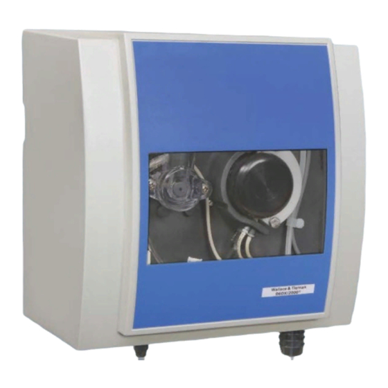
- Page 16 MICRO/2000® AND DEOX/2000® MODULE Cover Cell body with sensor Peristaltic pump Inlet shut-off valve Bypass Y-strainer with flow control valve Inlet control valve Drain hose Figure 1.3 W3T331759 / WT.050.585.003.UE.IM.1014...
-
Page 17: Table Of Contents
Check that the transport packaging is undamaged. In the event of damage please inform the transport company immediately. If the device is damaged, please contact the respective Evoqua Water Technologies immediately. Keep the packing until the unit has been correctly installed and put into operation. -
Page 18: Storage
MICRO/2000® AND DEOX/2000® MODULE 2.1.2 Storage Store the unit and the sensors in a dry condition without any residual water in a dry place. Storage temperature, see section 1.1, "Specifications". Installation The device must be protected against rain, frost and direct sunlight and should not be installed outdoors. -
Page 19: Insert The Sensors And Connect
MICRO/2000® AND DEOX/2000® MODULE Insert wet finger into supplied grit tube (see Figure 2.1). Some grit will cling to tip of wet finger (see Figure 2.2). Dip finger into sample cell water, grit will rinse into flow (see Figure 2.3). Replace probe in sample cell. -
Page 20: Installing Reagent Hardware
MICRO/2000® AND DEOX/2000® MODULE IC board Housing Relay terminal Sensor cable duct Terminal signal inputs/outputs Sensor measuring module Coding switch IC board Connecting plug or terminal at the front panel board Figure 2.4 - Electronic Module Cutaway Connecting the sensor cables: Place the sensor cables with the attached glands into the cable ducts of the housing. -
Page 21: Connecting The Sample Water
MICRO/2000® AND DEOX/2000® MODULE Before attaching the reagent bottle mounting brackets to mounting surface, install the retaining strap through the slots in the bracket. The brackets should be located within 1.2m (4 feet) of the analyser. • Install the reagent tubing as follows: Uncoil the reagent tubing segment(s) (one per liquid reagent) and remove the rigid tubing segments (1/32-inch O.D., 330mm long (13-inch long)) from the protective packaging. - Page 22 MICRO/2000® AND DEOX/2000® MODULE A well-designed sampling system minimizes response time, prevents fouling of the sample line plumbing and the analyser, and provides a fully developed turbulent flow to the analyser. Response time is minimized by locating the analyser close to the point of sample take-off and by designing for a moderately high flow velocity in the sample line, 1.5 m/s (5 ft/sec).
-
Page 23: Connect The Device To The Power Supply
MICRO/2000® AND DEOX/2000® MODULE residual during the sample transit time in the sample line. For sample line dosing, the cleaning agent is periodically injected into the sample line near the sample intake point. A self-flushing, 1/2-inch Y-strainer is provided and should be located at the analyser. -
Page 24: Mounting The Housing Covers
MICRO/2000® AND DEOX/2000® MODULE WARNING: The device is not equipped with a mains switch and is in operation as soon as the supply voltage is applied. When connecting system components (e.g. devices, motors, pumps), the system components must be switched off. CAUTION: To ensure safe and correct commissioning, knowledge of the operation, connected electrical load, measurement signals, cable assignment and fuse protection of the connected devices and machines and the relevant... -
Page 25: Top Hat Rail Assembly
MICRO/2000® AND DEOX/2000® MODULE TOP HAT RAIL ASSEMBLY - DIMENSIONS MICRO/2000® and DEOX/2000® Flow Block 50.590.100.050 ISSUE 1 7-14 W3T331759 / WT.050.585.003.UE.IM.1014... - Page 26 MICRO/2000® AND DEOX/2000® MODULE WALLMOUNT ASSEMBLY - DIMENSIONS MICRO/2000® and DEOX/2000® Flow Block 50.590.100.060 ISSUE 1 7-14 W3T331759 / WT.050.585.003.UE.IM.1014...
- Page 27 MICRO/2000® AND DEOX/2000® MODULE IC-Board (Mother board) MICRO/2000 Alarm 1 Power DEOX/2000 WET SIDE L2/N E Green Cable supplied PE L2/N L1 Power L1/N 100...125VAC L1/L2 220...240VAC prefuse max. 100...240VAC 16A power consumption. 15W 1) Shield earthed at one end Temp Digital-In Feedback signal...
- Page 28 MICRO/2000® AND DEOX/2000® MODULE Relay Outputs - MICRO/2000 - DEOX/2000 Wet Side Power Connection Power 21 20 19 Supply Power Power Cable L1/N 100...125 VAC Fitted L1/L2 220...240 VAC prefuse max: 230/115V AC 6A Sensor Module 1 Power Cable Fitted See Drg 50.585.155.050F Sensor Module 2 MFC - SCHEMATIC WIRING...
- Page 29 MICRO/2000® AND DEOX/2000® MODULE 3 pot cells Main +temp. sensor Board Pt1000 1 2 3 4 5 6 7 8 MICRO/2000® DEOX/2000® 1) Shield earthed at one end SFC Sensor/Module Connection for CE Version 50.585.155.050F ISSUE 0 9-10 W3T331759 / WT.050.585.003.UE.IM.1014...
- Page 30 MICRO/2000® AND DEOX/2000® MODULE W3T331759 / WT.050.585.003.UE.IM.1014...
- Page 31 MICRO/2000® AND DEOX/2000® MODULE SETUP AND CONTROL FUNCTIONS List of Contents Section General Information Overall function 3.1.1 MICRO/2000® and DEOX/2000® flow block assembly 3.1.2 Measurement Inputs MICRO/2000® and DEOX/2000® flow block assembly 3.2.1 Temperature measurement 3.2.2 General Information The SFC and MFC are measuring and control devices for use on potable water, industrial process water and waste water.
-
Page 32: Overall Function
MICRO/2000® AND DEOX/2000® MODULE The menus are easy to use, displayed in plain text and are selected using softkeys. 3.1.1 Overall function Possible measured values: • Free chlorine*, total chlorine*, potassium permanganate*, chlorine dioxide* ozone* (MICRO/2000® 3-electrode cell) • Total chlorine*, sulphur dioxide* (DEOX/2000® 3-electrode cells) * These measurements are automatically temperature-compensated. -
Page 33: Micro/2000® And Deox/2000® Flow Block Assembly
MICRO/2000® AND DEOX/2000® MODULE 3.2.1 MICRO/2000® and DEOX/2000® flow block assembly MICRO/2000® and DEOX/2000® Flow Block Assembly - 3 Electrode Measurement for Total and Free Cl2, ClO2, O3, or KMnO4 (MICRO/2000®), Total Cl2 and SO2 or NaHSO3 (DEOX/2000®). A sensor module (“DES” for 3 electrode cells) and terminal strips are used to connect the MICRO/2000®... - Page 34 MICRO/2000® AND DEOX/2000® MODULE 3 Electrode Cell Impeller Peristaltic Pump Internal Bypass Calibration Sample Flow Control 3-Way Valve Valve Flushing Y-Strainer Drain Chamber Buffer Potassium Shut Off to Waste Reservoir Iodide Reservoir Valve 5 litre 5 litre Relief Valve Set at 2 bar (30 PSI) (1 Gallon US) (1 Gallon US) Priming...
- Page 35 MICRO/2000® AND DEOX/2000® MODULE Iodine is used as the “biasing reagent” because it is less likely (and slower to react with organic oxidant demand, making determination of residuals more reliable than a hypochlorite (chlorine) biased measurement. Because iodine is not stable in solution (i.e., is volatized and reacts readily), Potassium iodate solution is reacted with potassium iodide (KI) and releases iodine as used.
-
Page 36: Temperature Measurement
MICRO/2000® AND DEOX/2000® MODULE 3.2.1.4 Probe installation The probe should be installed in the analyser after the rest of the analyser installation (mounting, plumbing, wiring) is completed and inspected. CAUTION: Do not fill the probe with electrolyte until immediately before it is installed in the analyser. - Page 37 MICRO/2000® AND DEOX/2000® MODULE OPERATION List of Contents Section Display and Operator Controls Operator controls 4.1.1 Notes On Operation Operation 4.2.1 Menu Structure Calibration Temperature Calibration 4.4.1 MICRO/2000® & DEOX/2000® Calibration 4.4.2 Errors Display and Operator Controls Graphic display and operating panel All information is shown on the graphic display.
- Page 38 MICRO/2000® AND DEOX/2000® MODULE The exact depiction of the individual parameters on the graphic display is described in section 4.3, Menu Structure. 4.1.1 Operator controls Softkey • Activate the function shown on the graphic display with the keys. • Move up one level. •...
- Page 39 MICRO/2000® AND DEOX/2000® MODULE Switch between the basic • Press the up or down key displays and trend graphs Select menu • Press the “MENU” softkey to select the menu • Press the “CAL” softkey to calibrate • Press the “MODE” softkey to set the operating mode Select a menu item in the •...
- Page 40 MICRO/2000® AND DEOX/2000® MODULE The “Calibration” and “Mode” menus are opened with the corresponding soft keys directly from the basic display. All other menus can be accessed with the “MENU” softkey. Calibration CAUTION: The electrode fingers or membranes on the sensors are extremely sensitive.
- Page 41 MICRO/2000® AND DEOX/2000® MODULE Standard Solution Method Select the 1 Point calibration method in the calibration menu. Create a 500 ml sample solution of a desired concentration within the intended operating range. Allow the sample solution to pump through the sample line for aminimum of 10 minutes using the 3-way inlet valve (see Figure 4.3).
- Page 42 MICRO/2000® AND DEOX/2000® MODULE 4.4.2.4 DEOX/2000® BIAS calibration In performing the BIAS calibration, the slope is calibrated by directly measuring the residual “bias” resulting from the reagents (iodine) added to the cell. This bias can be directly determined only by operating the analyser on zero residual, chlorine demand free water (distilled water), so that the iodine bias residual is the only source of residual.
- Page 43 MICRO/2000® AND DEOX/2000® MODULE The pump is now drawing sample from the beaker. Allow the sample to purge the pump and cell for five minutes. Wait for the measured concentration to stabilize. Watch the water level in the flask during this period and refill as required. Do not allow the pump to suck in air, as this disrupts the calibration.
- Page 44 When the error has been remedied, the error message is automatically deleted. If you are unable to remedy the error yourself, please contact your local Evoqua Water Technologies service department. Table 4.1 - Error Message Error message...
- Page 45 Error The following table shows and explains possible errors which can occur. If you are unable to remedy the error yourself, please contact the Evoqua Water Technologies service department. Table 4.2 - Errors Error...
- Page 46 MICRO/2000® AND DEOX/2000® MODULE W3T331759 / WT.050.585.003.UE.IM.1014...
- Page 47 MICRO/2000® AND DEOX/2000® MODULE MAINTENANCE List of Contents Section Maintenance Schedules Check for tightness 5.1.1 Check the cell sand 5.1.2 Maintaining MICRO/2000® and DEOX/2000® Flow Block Assembly Wetside panel removal and replacement 5.2.1 Occlusion ring removal and replacement 5.2.2 Pump, rotor, rollers and thrust washer Removal and replacement 5.2.3 Pump tubing units replacement...
- Page 48 MICRO/2000® AND DEOX/2000® MODULE 5.1.1 Check for tightness Check the entire measuring device including all screw connections for leakage. Repair any leakage points immediately. NOTE: Air bubbles in the sample water influence the measuring accuracy. The cause must be determined and remedied. 5.1.2 Checking the cell sand Check that there is sufficient sand in the cell body.
- Page 49 MICRO/2000® AND DEOX/2000® MODULE Disconnect the liquid reagent tubing from the inlet and discharge of the metering pump. Disconnect the water sample tube from the panel inlet. Disconnect the drain tubing from drip tray outlet. Remove the clamps holding the probe cable, if probe will be serviced.
- Page 50 MICRO/2000® AND DEOX/2000® MODULE Turn off the water supply to the analyser. Remove the wetside panel (optional). See paragraph 5.2.1, Wetside Panel Removal and Replacement. Using a 7/16-inch socket wrench, remove the two bolts (with washers) attaching the occlusion ring to the panel. Lift off the occlusion ring.
- Page 51 MICRO/2000® AND DEOX/2000® MODULE When the rotor body is removed, check the rollers, roller shafts, thrust washer, the shaft bearing, and shaft bore in the rotor body for signs of excessive wear, damage, or corrosion. Some residue on the roller shafts and inside the rollers is normal.
- Page 52 MICRO/2000® AND DEOX/2000® MODULE The shaft bore has a sliding fit on the shaft, so there may be a slight resistance to the sliding. If the resistance seems excessive, back-off the set screw a quarter turn and twist the rotor body back and forth slightly as it slides back onto the shaft.
- Page 53 MICRO/2000® AND DEOX/2000® MODULE Remove the tube units only when replacement units are readily available, so there is no confusion about how to reconnect the new tube units. • Removal of the tube segments is as follows: Disconnect power to the wetside. Disconnect the sample and reagent tubing from the fittings at the ends of the tubing segments.
- Page 54 MICRO/2000® AND DEOX/2000® MODULE The sample tube unit (B) fits into the large groove (E) on the tube retainer (F) and the large groove (I) on the rollers (G). Guide the (new) tube unit through the small (D) or large (E) groove in the lower end of the tube retainer (F) and slide the unit up through the groove until the lower tube stop (J) is against the outer surface of the tube retainer (F).
- Page 55 MICRO/2000® AND DEOX/2000® MODULE Tap in the new bearing until it is flush with the end of the bearing support. Place the long side of a flat bladed screwdriver over the bearing face and tap with a hammer. Make sure the new bearing is square to the bearing support bore.
- Page 56 MICRO/2000® AND DEOX/2000® MODULE Press new impeller shaft bearing into back of seal adapter. Apply a small quantity of silicone grease to front and back bearing shaft hole. Apply a small quantity of silicone grease to the back side (the frontside is the concave side) of the new U-cup before installation into the seal adapter.
- Page 57 MICRO/2000® AND DEOX/2000® MODULE Remove the motor with the impeller shaft. If the motor is being replaced, remove the impeller shaft and coupling from the motor. 5.2.7.2 Replacement Replacement is basically the reverse sequence of removal. Grease the impeller shaft seal, with suitable silicone grease, before reinstalling it on the front of the panel assembly.
- Page 58 MICRO/2000® AND DEOX/2000® MODULE 5.2.8.2 Impeller Shaft Installation If the impeller shaft coupling is removed from the impeller motor install the coupling on the motor shaft against the front face of the motor. Tighten the retaining setscrew (using a 3/32-inch Allen wrench). Slide the impeller shaft into the coupling until it bottoms against the end of the motor shaft.
- Page 59 MICRO/2000® AND DEOX/2000® MODULE 5.2.10 Probe electrolyte and electrodes The analyser performs best when the probe is left undisturbed as much as possible. Manual cleaning of the probe electrodes should not be done unless necessary, as this will require recalibration of the analyser. CAUTION : Do not sand the probe electrodes! The electrodes are made of a thin film of platinum and cannot be replaced or repaired.
- Page 60 MICRO/2000® AND DEOX/2000® MODULE WARNING: Hydrochloric acid and muriatic acid will severely irritate eyes and cause chemical burns to skin. Always wear appropriate protective equipment during handling. When diluting acid, always pour acid into the water, never pour water into acid. It is the responsibility of the user of the equipment to obtain and follow the safety precautions of the manufacturer of the hazardous material.
- Page 61 MICRO/2000® AND DEOX/2000® MODULE I LLUSTRATIONS List of Contents Section MICRO 2000 and DEOX 2000 CE Wetside Enclosure Asssembly 50.580.000.035A&B MICRO 2000 and DEOX 2000 Wetside Casting Assembly 50.580.000.040A&B Micro CE - DEOX 2000 wetside GAA1177 sheets 2 & 4 W3T108351 Waterline Kit.
- Page 62 MICRO/2000® AND DEOX/2000® MODULE MICRO/2000® AND DEOX/2000® CE WETSIDE ENCLOSURE ASSEMBLY - PARTS — W3T140748 (240V) W3T332446 (115V) 50.580.000.035A ISSUE 2 7-14 W3T331759 / WT.050.585.003.UE.IM.1014...
- Page 63 MICRO/2000® AND DEOX/2000® MODULE PART NO. QTY. DESCRIPTION W2T1535 Grounding lug W2T504179 Bootlace ferrule, insulated, 1.5Mm W3T160551 M20 cable gland W2T416769 Cable gland nut W2T416873 Din rail guide W2T365250 1/4" Flat seat hose barb W2T365251 Rivet W2T416875 Capacitor, 15μf±20x, 100v W2T416879 Enclosure mach'd W2T416880...
- Page 64 MICRO/2000® AND DEOX/2000® MODULE MICRO/2000® AND DEOX/2000® WETSIDE CASTING ASSEMBLY - PARTS — W3T140748 (240V) W3T332446 (115V) 50.580.000.040B ISSUE 3 7-14 W3T331759 / WT.050.585.003.UE.IM.1014...
- Page 65 MICRO/2000® AND DEOX/2000® MODULE PART NO. QTY. DESCRIPTION W2T8855 Seal, adapter, pvc W3T172188 Label, warning W2T416867 Casting, al6061 W2T416872 Drip trough, pvc W3T108352 Name tag W2T416876 Motor, reversible, 600/500 rpm W2T17575 Screw, #8-32 x 1/2" lg. W2T375790 Bolt, 1/4-20 x 2-1/4" lg. W2T19395 Set screw, #6-32 x 3/16"...
- Page 66 MICRO/2000® AND DEOX/2000® MODULE MICRO CE - DEOX 2000 WETSIDE GAA1177 sheet 2 issue 6 W3T331759 / WT.050.585.003.UE.IM.1014...
- Page 67 MICRO/2000® AND DEOX/2000® MODULE MICRO CE - DEOX 2000 WETSIDE GAA1177 sheet 4 issue 6 W3T331759 / WT.050.585.003.UE.IM.1014...
- Page 68 MICRO/2000® AND DEOX/2000® MODULE PART NO. QTY. DESCRIPTION W2T19400 Reducing bushing, pvc, 1/4" x 1/2" npt W2T16766 Nipple, pvc, 1/4" x 1/4" W2T19799 Nipple, pvc, 1/2" W2T14737 Elbow, pvc, 90° W2T12055 Union nut, pvc, 1/2-20 thread W2T16217 Tubing, polyethylene, 1/4" id, 3 ft W2T15468 Valve, cci pvc W2T13310...
- Page 69 MICRO/2000® AND DEOX/2000® MODULE W3T108351 WATERLINE KIT - PARTS LIST 50.580.000.050B ISSUE 1 9-10 W3T331759 / WT.050.585.003.UE.IM.1014...
- Page 70 MICRO/2000® AND DEOX/2000® MODULE PART NO. QTY. DESCRIPTION W2T11685 Tubing (.020 ID) norprene W3T110057 Bottle W2T11234 Rigid tubing (.027 ID), 13" lg. W2T16958 1/4" lockwasher (SS) W2T18825 Mach. Screw (rd.Hd.,SS) 1/4"-20 x 3/4" lg. W2T417965 Hex. jam nut (SS) 1/4"-20 W2T14861 Strap W2T13382...
- Page 71 MICRO/2000® AND DEOX/2000® MODULE COMPLETE DEVICES , RETRO FIT KITS & SPARE PARTS List of Contents PARA. NO. Retrofit Sets Spare Parts and Consumables MICRO/2000® and DEOX/2000® Spare Parts W3T331759 / WT.050.585.003.UE.IM.1014...
- Page 72 MICRO/2000® AND DEOX/2000® MODULE Retrofit Sets 3-electrode cell MICRO/2000® 3-electrode cell DEOX/2000® with with P T1000 P T1000 W3T158828 - Plug-in card with W3T158829 - Plug-in card with terminals terminals W3T158830 - with optional Process W3T158831 - with optional Process Control Control Spare Parts and Consumables...
- Page 73 MICRO/2000® AND DEOX/2000® MODULE DEOX 2000 Old Part No New Part No. Chemical pack Comprising: AAB1098 W3T291579 5 litres acetic acid U86584 W2T636701 5 litres de-ionised water U86586 W2T636702 Potassium iodide 250g AAA8160 W2T633474 Potassium iodate solution AAB1128 W2T633562 MICRO 2000 Old Part No New Part No.
- Page 74 MICRO/2000® AND DEOX/2000® MODULE W3T331759 / WT.050.585.003.UE.IM.1014...
- Page 75 MICRO/2000® AND DEOX/2000® MODULE APPENDIX A MICRO 2000 Reagents List of Contents MICRO/2000® Flow Block Theory of Operation Preparation of Reagents - MICRO/2000® Preparation of pH Buffer Preparation of Potassium Iodide Solution for MICRO/2000® Preparation of Potassium Iodate Refilling Reagent Reservoirs Selection of Reagents Residual Form Chlorine dioxide and potassium permanganate...
-
Page 76: Preparation Of Reagents - Micro/2000
Preparation of pH4 Buffer This reagent is available from Evoqua Water Technologies premixed in one gallon plastic bottles. It may also be made on-site as follows: dissolve 919 grams of sodium acetate, trihydrate in approximately 1.5 litres of distilled water, then mix with 1.73 litres of glacial acetic acid and dilute... -
Page 77: Preparation Of Potassium Iodide Solution For Micro/2000
MICRO/2000® AND DEOX/2000® MODULE Preparation of Potassium Iodide Solution For MICRO/2000® NOTE: Potassium iodide solution is used only in the measurement of total chlorine. Therefore, this section does not apply to analyzers installed to measure free chlorine or potassium permanganate. Potassium iodide (KI) is added to distilled water and fed into the water sample by the metering pump when measuring total chlorine. -
Page 78: Refilling Reagent Reservoirs
MICRO/2000® AND DEOX/2000® MODULE Refilling Reagent Reservoirs WARNING: To avoid possible severe personal injury or equipment damage, observe the following: pH4 buffer and acetic acid will severely irritate eyes and cause chemical burns to skin. Always wear appropriate protective equipment during handling. -
Page 79: Residual Form
MICRO/2000® AND DEOX/2000® MODULE Residual Form 4.1.1 Chlorine dioxide and potassium permanganate monitoring The stability of the sample pH is not as critical when monitoring chlorine dioxide and potassium permanganate residuals as when measuring chlorine residuals. A sample pH change of 0.2 pH units between calibration will cause less than 5% error. -
Page 80: Total Chlorine Monitoring
MICRO/2000® AND DEOX/2000® MODULE 4.1.5 Total chlorine monitoring Potassium iodide liquid reagent must be added to the analyser sample for the measurement of total chlorine residual. The sample pH should be maintained between 4.0 and 4.7. The iodide solution is made by adding potassium iodide to one gallon of unchlorinated DI water. - Page 81 MICRO/2000® AND DEOX/2000® MODULE APPENDIX B DEOX/2000® Reagents List of Contents DEOX/2000® Theory of Operation Preparation of Reagents - DEOX/2000® Preparation of Potassium Iodide Solution for DEOX/2000® DEOX/2000® Theory Of Operation When a process requires super chlorination the effluent from it will have to be dechlorinated to some extent to allow discharge, either to a sewer or a natural water source.
- Page 82 MICRO/2000® AND DEOX/2000® MODULE NaHSO is used, 1.38 mg/l of hardness is removed. The stoichiometric relationship means that for every mg/l chlorine, 0.9 mg/l SO is required (often this is increased to 1.05 to eusure complete dechlorination) while for sodium bisulphite, 1.46 mg/l must be used. The alkalinity of chlorinated wastewater effiuent is usually in the region of 150 to 200 mg/l as CaCO Therefore if S0 is used, dechlorination of 10 mg/l would result in a...
- Page 83 MICRO/2000® AND DEOX/2000® MODULE If excess SO2 is present, this reacts as follows:- O ------> H O + I ------> H + 2HI Every mg/l of SO reacts with a mg/l of I and reduces the zero current signal. These reactions are illutrated in the following graph. mg/l Cl2 mg/l Cl2 / mg/l SO2 mg/l SO2...
- Page 84 MICRO/2000® AND DEOX/2000® MODULE WARNING: When servicing liquid reagent lines, pumps, or refilling reservoirs, turn off pumps to avoid possible squirting of reagent. Observe all safety precautions recommended by the reagent manufacturer or supplier. Preparation of Potassium Iodide Solution for DEOX/2000® Potassium Iodide (KI) solution is prepared by dissolving 166g KI in 5 litres of distilled water.
- Page 85 Evoqua Water Technologies Aftermarket Support and Service INTRODUCTION Every day, millions of people and thousands of companies rely on Evoqua CO-ORDINATION Water Technologies to help them meet their needs for clean water. Evoqua Water Technologies dedicated Customer Service Department is As the leading global provider of chemical dosing, metering, disinfection, co-ordinated from our Derby office.
- Page 86 Tel: +44 (0) 1732 771777 Email: info.uk@evoqua.com Wallace & Tiernan, Ionpure and Memcor are trademarks of Evoqua, its subsidiaries or affiliates, in some countries. All information presented herein is believed reliable and in accordance with accepted engineering practices. Evoqua makes no warranties as to the completeness of this information.
Need help?
Do you have a question about the Wallace & Tiernan MICRO/2000 and is the answer not in the manual?
Questions and answers