
Related Manuals for Evoqua DEPOLOX 400 M


Summary of Contents for Evoqua DEPOLOX 400 M
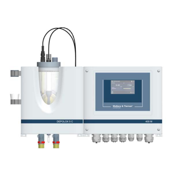
- Page 1 ® DEPOLOX 400 M ® WALLACE & TIERNAN DISINFECTION ANALYZER Version 1.14 and later INSTRUCTION MANUAL...
- Page 2 Translation of the original instruction. In some countries, DEPOLOX, OSEC, Barrier, Chem-Ad and Wallace & Tiernan are trademarks of Evoqua, its subsidiaries or affiliated companies. No part of this document may be reproduced in any form (printed, photocopy, microfilm, or any other procedure) or saved, processed, copied, or distributed using electronic data systems - without the express prior written con- sent of Evoqua Water Technologies GmbH.
-
Page 3: Table Of Contents
DEPOLOX® 400 M Contents Contents Introduction ................5 Target groups ......................5 Structure of the documentation ................5 Conventions......................5 Safety..................6 Intended use......................6 General safety instructions ..................6 Specific operating phases..................7 Warranty conditions....................7 Exclusion of liability ....................7 Description................. 8 General ........................8 Versions........................8 Configuration options....................9 Overview of sensors (DES sensors)................10 Optional accessories....................10 400 M electronics module..................11... - Page 4 DEPOLOX® 400 M Contents 5.14 Electrical installation..................... 48 5.15 Initial commissioning .................... 50 5.16 Replace 4-way mA output card................51 5.17 Shut-down......................51 5.18 Start-up ......................... 51 Operation ................52 Display and control elements ................52 “Measurement” menu..................53 “System“ menu ..................... 56 Web visualization....................
-
Page 5: Introduction
DEPOLOX® 400 M 1. Introduction Introduction WARNING Electrocution hazard. Target groups This operating manual provides the informa- tion required for installation, operating and ATTENTION maintenance personnel for the installation, Environmental hazard! operation and maintenance of the DEPOLOX® Do not throw away or burn the batteries! 400 M disinfection analyzer. -
Page 6: Safety
2. Safety DEPOLOX® 400 M Safety State-of-the-art technology The DEPOLOX® 400 M has been constructed in accordance with the technological state-of- Intended use the-art and the accepted rules of safety engi- The DEPOLOX® 400 M disinfection analyzer neering. However, if the DEPOLOX® 400 M is with installed sensors is designed exclusively used by persons who have not been adequa- for measurement of the parameters free chlo-... -
Page 7: Specific Operating Phases
DEPOLOX® 400 M 2. Safety Warranty conditions IT security The manufacturer offers IT security mecha- The following must be observed for compli- nisms for its products to support secure sys- ance with warranty conditions. If any of the tem operation. We recommend checking on a conditions are not met, the warranty is void. -
Page 8: Description
3. Description DEPOLOX® 400 M Description Free chlorine measurement with the DEPO- LOX® 5 C depends on the pH value. By using a pH measurement, the pH dependency of the General measurement can be compensated for within The DEPOLOX® 400 M disinfection analyzer a range of pH 6.00 to pH 8.75 (Cl ++). -
Page 9: Configuration Options
DEPOLOX® 400 M 3. Description Configuration options Y-style flow- DEPOLOX® 5 C VariaSens C through DEPOLOX® 5 C VariaSens C non- non- assembly Description pressurized pressurized pressurized pressurized non- version version version version pressurized version E D C F E D F E D A 3-Electrode cell (free A Fluoride sensor (only on... -
Page 10: Overview Of Sensors (Des Sensors)
3. Description DEPOLOX® 400 M Overview of sensors (DES sensors) 3-electrode cell Description (total (free (chlorine (DEPOLOX® 5 C) (ozone) chlorine) chlorine dioxide) Membrane-covered, Potentiostatic amperometrically Measuring 3-electrode cell Membrane-covered operating potentiostatic principle with platinum 2-electrode system 3-electrode system with electrodes integrated electronics Free Cl... -
Page 11: Electronics Module
DEPOLOX® 400 M 3. Description 400 M electronics module For connection to a visualization system, there is an optional 4-way mA output module, an RS485 interface and an Ethernet interface with 3.6.1 Design Modbus TCP and HTTP protocol. 3.6.3 Controller outputs The electronics module has a dosing contact for disinfection measurement. - Page 12 3. Description DEPOLOX® 400 M Acknowledgment “none“ Acknowledgment “simple ACK“ • The alarm symbol and the message sym- • The relay becomes active as soon as the bol light up in the event of an alarm and alarm is active. go out automatically when the condition •...
- Page 13 DEPOLOX® 400 M 3. Description Sample water monitoring • after expiry of the sample water monito- ring delay time: DANGER Dosing is switched off. Risk of injury or death Display: If there is a shortage of sample water or the NOTICE flow rate is too low, there is a risk of uncon- trolled dosing of chemicals.
- Page 14 3. Description DEPOLOX® 400 M 3.6.8 Relay outputs 3.6.9 Interfaces The electronics module has a maximum of six The interfaces are described in detail in chap- relays, each with a changeover contact. These ter 4. The following interfaces are available: switches are assigned various switching tasks •...
-
Page 15: Depolox® 5 C Flow Cell
DEPOLOX® 400 M 3. Description DEPOLOX® 5 C flow cell 3.7.2 Function The DEPOLOX® 5 C flow cell has a 3-electrode NOTICE cell and is available in a non-pressurized or The DEPOLOX® 5 C flow cell can be used for pressurized version. -
Page 16: Variasens C Flow Cell
3. Description DEPOLOX® 400 M VariaSens C flow cell The sample water flows tangentially into the 3-electrode cell ensures continual hydro- The VariaSens C flow cell is available in a non- mechanical cleaning of the sensor electrodes pressurized or pressurized version. The versi- with a special cleaning sand and thus prevents ons also differ in the number and layout of the the natural contamination of the electrode... - Page 17 DEPOLOX® 400 M 3. Description 3.8.2 Function The cell body contains the sensors and the LED glow stick. The sensors are installed in the NOTICE location holes in the cell body cover with stan- The VariaSens C flow cell can be used in dardized threaded connections or in special combination with membrane sensors for sensor holders.
-
Page 18: Y-Style Flow-Through Assembly
3. Description DEPOLOX® 400 M Y-style flow-through assembly 3.10 Sensors The Y-style flow-through assembly is available The sensors are screwed into the cell body in a non-pressurized version and can be fitted cover of the flow cell and connected to the with a pH, ORP (Redox) or fluoride sensor. - Page 19 DEPOLOX® 400 M 3. Description The pH sensor is installed in an electrolyte The ORP sensor is installed in an electrolyte reservoir (transport container) with diluted container with diluted electrolyte which pro- electrolyte which protects the sensitive mem- tects the sensitive membrane, keeps the brane, keeps the membrane moist and thus membrane moist and thus ensures that the ensures that the measuring cell is ready for...
- Page 20 3. Description DEPOLOX® 400 M 3.10.5 Membrane sensors TC3 (total 3.10.6 Membrane sensor CD7 (chlorine chlorine) and FC2 (free chlorine) dioxide) NOTICE NOTICE The membrane sensors TC3 and FC2 can be Membrane sensor CD7 can be installed in the installed in the non-pressurized and pressu- non-pressurized and pressurized version of rized version of the VariaSens C flow cell.
-
Page 21: Technical Data
DEPOLOX® 400 M 3. Description 3.11 Technical data 3.11.1 400 M electronics module (module name E02) Dimensions (WxHxD) 12.6“ x 12.2“ x 6“ (320 x 311 x 153 mm) Weight approx. 7.7 lbs (3.5 kg) Housing Protection rating IP66 100 to 240 V AC ± 10% 50 to 60 Hz or Mains connection 24 V DC, 15 W 4.3”... - Page 22 3. Description DEPOLOX® 400 M Type 6x changeover contact with integrated fuse, replaceable, type TR5 3,15 A T High nominal breaking 5A 250V AC, 1250VA max. (resistive load) 1A 250V AC, 250VA max. (cos ɸ = 0,4) 5A 30V DC, 150W max. (resistive load) Switching voltage max.
- Page 23 DEPOLOX® 400 M 3. Description 3.11.2 DEPOLOX® 5 C flow cell (module name D02) 9.96“ x 14.76“ x 6.42“ Dimensions (WxHxD) (253 x 375 x 163 mm) Housing Weight approx. 5.5 lbs (2.5 kg) Inlet. G 1/2” A thread connection Non-pressurized version Outlet: Connecting nipple for hoses ID 6 mm...
- Page 24 3. Description DEPOLOX® 400 M 3.11.3 VariaSens C flow cell (module name D02) 9.96“ x 14.76“ x 6.42“ Dimensions (WxHxD) (253 x 375 x 163 mm) Housing Weight approx. 5.5 lbs (2.5 k)g Pressurized and non-pres- Inlet and outlet: Connections surized version G 1/2”...
- Page 25 DEPOLOX® 400 M 3. Description 3.11.5 Sensors pH sensor Single-rod measuring cell with universal membrane glass, salt reserve, Version zirconium dioxide diaphragm, polymerized solid electrolyte, Ag/AgCl reference electrode Range pH 0 to 12 (temporarily to pH 14) Working tempera- 23 to 176°F (-5 to +80°C) ture range Operating pressure 6 x 10...
- Page 26 3. Description DEPOLOX® 400 M Membrane sensor Membrane sensor TC3 (total chlorine) FC2 (free chlorine) Total chlorine (= free chlorine + Measured value Free chlorine combined chlorine) Range 0.05 to 20.00 mg/l (ppm) Swimming pool, drinking and Swimming pool and drinking Area of application process water water...
- Page 27 DEPOLOX® 400 M 3. Description Membrane sensor Membrane sensor CD7 (chlorine dioxide) OZ7 (ozone) Chlorine dioxide, selective toward Ozone, selective toward Cl , Br , Br , cross-sensitivity to Measured value , cross-sensitivity to ClO , peracetic acid peracetic acid Power supply unipolar +12 –...
-
Page 28: Interfaces
4. Interfaces DEPOLOX® 400 M Interfaces DANGER Risk of injury or death! External voltages may still be connected even if the operating voltage is switched off. USB interface The electronics module is equipped internally with a USB interface. It is used to update the firmware via USB stick (chapter 6.5) or for use as a data logger via USB stick. - Page 29 DEPOLOX® 400 M 4. Interfaces The integrated 2-port switch replaces additio- Meaning of the LED: nal external switch assemblies. To avoid long • green lights up: Ethernet connection esta- process times, we recommend that you do not blished daisy-chain more than three devices via the •...
- Page 30 4. Interfaces DEPOLOX® 400 M Web view in the browser: 4.3.3 Network setting under Windows 10 Start the browser, e.g. Firefox or Internet Windows 10 automatically establishes a net- Explorer. work connection as soon as a network card is Enter the IP address of the electronics detected in the PC or laptop computer.
-
Page 31: Modbus Tcp Interface
DEPOLOX® 400 M 4. Interfaces Under the menu “Ethernet properties,” Windows 10 with an alternative configuration select the element “Internet protocol Ver- With Windows 10, it is also possible to set an sion 4 (TCP/Pv4).” Only the element alternative configuration. “Internet protocol Version 4 (TCP/IPv4)"... - Page 32 4. Interfaces DEPOLOX® 400 M 4.4.1 Data formats The table below contains the data format used for transmission of the process data: Data type Size (bit) Typical names Value range min. Value range max. INT8 -128 UINT8 INT16 -32.768 32.767 UINT16 65.535 INT32...
- Page 33 IP adress of the device, e.g. 192.168.200.11 Port: 502 Modbus Type Access Designation Description Register Byte System information 400001 ASCII System name e.g. "DEPOLOX 400 M" 400011 ASCII Software Version e.g. "V:1.00" 400016 ASCII act. date e.g. "21.02.17" 400021 ASCII act. time e.g. "13:16"...
- Page 34 4. Interfaces DEPOLOX® 400 M Modbus Type Access Designation Description Register Byte (Ch.5) Temperature - Measurement 400160 FLOAT Measured value 400162 ASCII Measured unit "°C"; "°F" 400167 FLOAT Lower range 0,0°C; 32,0°F 400169 FLOAT Upper range 50,0°C; 122,0°F 400171 400173 Status messages 400300 UINT16...
- Page 35 DEPOLOX® 400 M 4. Interfaces Modbus Type Access Designation Description Register Byte 400304 Operation mode controller UINT16 1 (chlorine) MAN. Auto Controller Aus Adaption running Controller stop (Yout=0%) Controller freeze (Yout=Yout) Controller Yout=100% Eco Mode switching Controller standby 400305 400306 400307 400308 400310...
- Page 36 4. Interfaces DEPOLOX® 400 M Modbus Type Access Designation Description Register Byte 400314 UINT32 Error code pH/Fluoride (Ch.2) Coding see Reg. 400310 400318 UINT32 Error code ORP (Redox) (Ch.3) Coding see Reg. 400310 400326 UINT32 Error code temperature (Ch.5) Coding see Reg. 400310 (Ch.1) Desinfection - Controller parameter (DES sensor) 401000 FLOAT...
- Page 37 DEPOLOX® 400 M 4. Interfaces Modbus Type Access Designation Description Register Byte (Ch.3) Redox - Limits 401074 FLOAT Min. value 1 Lower range - Max 1 401076 FLOAT Max. value 1 Min 1 - Upper range 401078 FLOAT Hysteresis value 1 1 - 25 Digit 401080 FLOAT...
-
Page 38: Installation
5. Installation DEPOLOX® 400 M Installation Storage Electronics module, flow cell, Y-style flow- through and sensors must be stored in dry Scope of delivery condition without any residual water in a dry The scope of delivery includes the following, place that is not exposed to the elements. depending on the version selected: Shut-down •... -
Page 39: Installation Of The Module
DEPOLOX® 400 M 5. Installation Connect the sample water outlet (chapter NOTICE 5.9). • Install the flow cell to the left of the Prepare VariaSens C (chapter 5.11) electronics module. • Install the fine filter • Leave a clearance of at least 250 mm Prepare DEPOLOX®... - Page 40 5. Installation DEPOLOX® 400 M 5.5.3 Dimension drawing (Example flow cell, pressurized and electronics module)
-
Page 41: Removing And Fittting The Housing Cover
DEPOLOX® 400 M 5. Installation Removing and fittting the 5.5.4 Y-style flow-through assembly housing cover Using mounting clamps (not included in the scope of delivery), screw the Y-style 5.6.1 Flow cell flow-through assembly to the solid wall Removing below the electronics module. •... -
Page 42: Installing The Optional Strainer
5. Installation DEPOLOX® 400 M Installing the optional strainer • The pressure in the sample water inlet must always be within a range of min. 4 to Release the screw joint on the sample max. 45 psig (min. 0.25 to max. 3.0 bar). water inlet with ball valve (A) (threaded The pressure in the sample water inlet connection G 1/2”... -
Page 43: Connecting The Sample Water Outlet
DEPOLOX® 400 M 5. Installation 5.10 Prepare the DEPOLOX® 5 C flow cell 5.10.1 Removing the felt ring In order to keep the diaphragm in the DEPO- LOX® 5 C flow cell moist and prevent crystalli- zation of the electrolyte solution during storage, a moist felt ring is inserted in the space between the electrolyte storage tank and electrode. - Page 44 5. Installation DEPOLOX® 400 M 5.10.2 Removing and replacing the transport plug NOTICE Before commissioning the DEPOLOX® 5 C flow cell, the transport plug must be remo- ved from the electrolyte storage tank and replaced with the stopper provided. DEPOLOX® 5 C non-pressurized version Remove the yellow protection plug from the electrolyte storage tank.
-
Page 45: Prepare The Variasens C Flow Cell
DEPOLOX® 400 M 5. Installation Make sure that the opening and the thread are clean; if necessary, rinse with distilled water. Insert sealing plug or sensor into the cell body cover. Open the ball valve on the sample water inlet. On the pressurized version, open the ball valve on the sample water outlet. - Page 46 5. Installation DEPOLOX® 400 M Sensor configuration Y-style flow- DEPOLOX® 5 C DEPOLOX® 5 C VariaSens C VariaSens C through assembly non-pressurized pressurized non-pressurized pressurized non-pressurized version version version version version F E D E D C F E D 3-Electrode cell (free chlorine) A Fluoride sensor (only on non- A pH-, ORP...
-
Page 47: Connecting Sensors
DEPOLOX® 400 M 5. Installation 5.13 Connecting sensors 5.13.1 Connect the sensor to the flow cell NOTICE Remove the red sealing plug (position A). • The sensor cable glands on the electro- Plug multi-sensor into the flow control nics module are special cable glands and valve (position A). -
Page 48: Electrical Installation
5. Installation DEPOLOX® 400 M 5.14 Electrical installation DANGER Risk of injury or death! External voltages may still be connected even if the operating voltage is switched off. The electronics module must be de-energi- zed before opening it. WARNING Risk of injury or damage to the device! •... - Page 49 DEPOLOX® 400 M 5. Installation 5.14.1 ORP sensor measuring module WARNING Disconnect the electronics module from Risk of injury or damage to the device! the power supply. • The DEPOLOX® 400 M is not equipped Remove the housing cover of the electro- with a mains switch and is in operation as nics module.
-
Page 50: Initial Commissioning
5. Installation DEPOLOX® 400 M 5.15 Initial commissioning Following complete mechanical and electrical installation, initial commissioning can be car- DANGER ried out. Please check that the following con- ditions are met: Risk of injury or death! The DEPOLOX® 400 M must not be operated •... -
Page 51: Replace 4-Way Ma Output Card
DEPOLOX® 400 M 5. Installation 5.16 Replace 4-way mA output card 5.17 Shut-down DANGER DANGER Risk of injury or death! Risk of injury or death! External voltages may still be connected External voltages may still be connected even if the operating voltage is switched off. even if the operating voltage is switched off. -
Page 52: Operation
6. Operation DEPOLOX® 400 M Operation Main scruture From the main menu, you can call up the sys- tem settings, the measured values menus and Display and control elements the controller menus. To access the corre- The colored graphic display with capacitive sponding menus, tap the Measurement menu touchscreen is the display and control ele- fields or tap the... -
Page 53: Measurement" Menu
DEPOLOX® 400 M 6. Operation “Measurement” menu Symbols Meaning This menu shows the current measured value Message/error active and the sensor signal. All settings relating to Tap the symbol to open the mes- measurements, such as range, limit values, sage window. controller settings and calibration must be •... - Page 54 6. Operation DEPOLOX® 400 M Chlorine measurement parameters pH measurement parameters Measurement Measurement Range Range Range end: Range end: pH 0.00 to pH 14.00 1.00 / 2.00 / 5.00 / 10.00 / 20.00 mg/l or Range start: pH 0.00 to pH 14.00 Measurement filter: off/low/middle/strong 200 / 500 µg/l or ppd Limits...
- Page 55 DEPOLOX® 400 M 6. Operation ORP (Redox) measurement parameters Maintenance intervals Measurement Calibration Range Message: On/Off Range end: 600/700/800/900/1000 Interval: 2 to 90 Range start: 0/100/200/300/400 Next maintenance on: Date Measurement filter: off/low/middle/strong Reset maintenance: Execute Limits Cell Limits value Message: On/Off Max: within range Interval: 10 to 365...
-
Page 56: System" Menu
6. Operation DEPOLOX® 400 M “ “System“ menu 6.3.1 Operation mode“ menu Access to the operating and configuration NOTICE level of the electronics module is possible via This function is only available if the parame- the System menu. All setting parameters not ter “Disinfection controller = On”... - Page 57 DEPOLOX® 400 M 6. Operation Calibration - System menu Press calibration selection, see “Calibrat- Call up the Home menu. ion selection” on page 57. Tap the symbol. Carry out sensor calibration as described in chapter 6.6. See “Example ”Cl2 free calibration””...
- Page 58 6. Operation DEPOLOX® 400 M “ Example ”Cl free calibration” 6.3.3 Inputs and Outputs“ menu Tap up the Home menu. The digital inputs and the mA outputs are con- Tap the Calibration menu in the Sys- figured in this menu. tem menu or the symbol in the Measu- Call up the Home menu.
- Page 59 DEPOLOX® 400 M 6. Operation Example Alarm 1/2/3/4 To transfer a measurement signal, e.g. Cl , via Designation: the mA output, the following setting is requi- A customer-specific alarm name can be red: defined. This name is displayed in the message window (main menu) when mA output Settings...
- Page 60 6. Operation DEPOLOX® 400 M 6.3.6 ”Settings” menu Hold Function: On/Off The device settings not relating to measured The hold function is used to either buf- values are configured in the Settings menu. fer all measured values or keep them constant during calibration.
- Page 61 DEPOLOX® 400 M 6. Operation Max. dosing time: 00:00 to 10:00 h Unlock pattern: This parameter defines a monitoring Menu for entry of a Level 2 unlock pat- time which specifies the maximum time tern. The entry must be repeated as the controllers may require before the confirmation.
- Page 62 6. Operation DEPOLOX® 400 M 6.3.7 ”Information” menu Connection - RS485 interface Various system information, e.g. the installed Function: Off or RS485 WT software version, is described in this menu. Selection of the RS485 Interface func- tion. 6.3.8 ”User administration“ menu The RS485 Interface supports bus com- The electronics module offers the option of munication with the Process Monitoring...
- Page 63 DEPOLOX® 400 M 6. Operation User symbol blue = Level 3 NOTICE • User logged in on Level 3. When access control is disabled, all pass- • Read rights for and write access to all words and locking codes entered are dele- device settings ted.
-
Page 64: Web Visualization
6. Operation DEPOLOX® 400 M Web visualization 6.3.9 User administration web visuali- zation The web views integrated in the DEPOLOX® User administration via web visualization 400 M allow you to visualize the measure- comprises two levels. At the factory, these ments and setting parameters via a standard two user levels are disabled and preset to “0.”... -
Page 65: Firmware Update
Software number: NOTICE Display software number A firmware update can be downloaded free Serial number: of charge from the homepage of Evoqua Display device serial number Water Technologies GmbH. IP configuration DANGER IP: Enter a fixed IP address Risk of injury or death! -
Page 66: Calibration
6. Operation DEPOLOX® 400 M Calibration When calibrating the measurements, variati- ons in the calibration solutions, buffer soluti- ons or comparative measurements are adjusted. Calibration is performed for new devices (first commissioning) and to recali- brate existing measuring instruments in accor- dance with maintenance regulations. - Page 67 DEPOLOX® 400 M 6. Operation To enable the calibration check interval, NOTICE set the parameter “Message” to “On” When the sample water supply has been under the heading Calibration and, under stopped, the display first drops rapidly, and “Interval,” enter the number of days after after approximately one minute slowly which you wish to receive a reminder to approaches zero.
- Page 68 6. Operation DEPOLOX® 400 M pH 7 alignment Offset alignment Press the “pH 7” parameter. If there is a difference between the displayed Close the sample water inlet and sample pH value and a pH value measured manually, water outlet and briefly open the flow cell this difference can be compensated for and drain valve to release the pressure.
- Page 69 DEPOLOX® 400 M 6. Operation 12 Remove the ORP sensor from the top clip. 15 Tap the “Calibrate upper value” parame- 13 Screw the ORP sensor into the cell body ter. cover. 16 Place the beaker in the bottom clip and fill 14 Open the sample water inlet and outlet it with calibration solution 2.00 mg/l.
-
Page 70: Messages, Alarms And Errors
6. Operation DEPOLOX® 400 M Messages, alarms and errors Messages, alarms and errors are displayed on the electronics module with the colored mes- sage symbol (chapter 3.6.4). Error messages can occur that can be acknowledged or that can not be acknowledged. If several messages occur at the same time, the number of messages appears next to the symbol. - Page 71 DEPOLOX® 400 M 6. Operation Error message Cause Remedy Slope error The current difference required Check DES sensor. for span alignment over the entire Clean electrodes. measurement range was less than Check the pH value of the water the minimum value. (<...
- Page 72 6. Operation DEPOLOX® 400 M Error message Cause Remedy pH measurement is outside Measurement/Dosiering < 6,00 and >8,75 check pH Check measuring water, Maximum dosing The maximum dosing time set for calibration, dosing pump, time has been a control output has been excee- chemical storage sensor, sensor exceeded cable, measurement.
-
Page 73: Faults And Remedies
DEPOLOX® 400 M 6. Operation Faults and remedies NOTICE If it is not possible to remedy the fault or error yourself, please contact your affiliate. Error message Cause Remedy Turn external switch or fuse No power supply. No indication on device Check power supply, replace Device fuse defective. -
Page 74: Maintenance
7. Maintenance DEPOLOX® 400 M Maintenance 7.2 Maintenance intervals DANGER regularly • Sample water monitoring (chapter 3.6.6) Risk of injury or death! • DEPOLOX® 5 C: Check electrolyte level External voltages may still be connected even if the operating voltage is switched off. daily •... -
Page 75: Maintenance Parts Set For Flow Cell
DEPOLOX® 400 M 7. Maintenance 7.3 Maintenance parts set for flow 7.4 Checking for leaks cell Check the entire flow cell every day, including all screw connections, for leakage. Repair any 7.3.1 DEPOLOX® 5 C flow cell leaks immediately. non-pressurized version NOTICE Ascending air bubbles in the cell body influ- Part No. - Page 76 7. Maintenance DEPOLOX® 400 M 7.5.3 Checking diaphragms NOTICE The two diaphragms (A) in the electrolyte tank Steps 1 to 14, 22, and 25 to 34 apply only to form the connection between the reference replacement and cleaning of the electrode electrolytes and the sample water.
-
Page 77: Cleaning Or Replacing The Fine Filter Of Varia Sens C
DEPOLOX® 400 M 7. Maintenance Replacing reference electrode NOTICE 19 Replace the reference electrode. To do After 2 to 3 hours running-in time, perform this, screw the reference electrode out of a chlorine calibration. If necessary, repeat the electrolyte tank. Lightly moisten the the chlorine calibration after 24 hours. -
Page 78: Cleaning The Flow Rate Monitor And Non-Return Ball Valve
7. Maintenance DEPOLOX® 400 M 11 Fit the filter unit again. To do this, tighten the knurled nuts. 12 Fit and engage the housing cover of the flow cell. 13 Open the ball valves on the sample water supply and drainage line again. 14 Switch on the power supply. -
Page 79: Cleaning Or Replacing The Optional Strainer
DEPOLOX® 400 M 7. Maintenance 7.8 Cleaning or replacing the optio- 7.10 Replacing the battery nal strainer WARNING The optional strainer must be cleaned or Risk of injury or damage to the device! replaced regularly to avoid contamination or Only authorized and qualified electricians blockages. -
Page 80: Spare Parts, Accessories And Retrofit Kits
8. Spare parts, Accessories and Retrofit kits DEPOLOX® 400 M Spare parts, Accessories and Retrofit kits NOTICE For reasons of safety, only use original spare parts. Please contact our customer service if you need any spare parts. 8.1 400 M electronics module 400 M electronics module (module name E02) - W3T441932 Item Part.No. - Page 81 DEPOLOX® 400 M 8. Spare parts, Accessories and Retrofit kits...
-
Page 82: Depolox® 5 C Flow Cell
8. Spare parts, Accessories and Retrofit kits DEPOLOX® 400 M 8.2 DEPOLOX® 5 C flow cell DEPOLOX® 5 C Flow cell module (module name D02) non-pressurized version - W3T389205 Item Part No. Designation Item Part No. Designation W3T165266 Knurled nut W3T247776 Basic housing W3T172861... - Page 83 DEPOLOX® 400 M 8. Spare parts, Accessories and Retrofit kits...
-
Page 84: Depolox® 5 C Flow Cell
8. Spare parts, Accessories and Retrofit kits DEPOLOX® 400 M 8.3 DEPOLOX® 5 C flow cell DEPOLOX® 5 C flow cell (module name D02) pressurized version - W3T389210 Item Part No. Designation Item Part No. Designation W3T172556 O-ring W3T247776 Basic housing W3T320102 Cell body cover W3T247777... - Page 85 DEPOLOX® 400 M 8. Spare parts, Accessories and Retrofit kits...
-
Page 86: Variasens C Flow Cell
8. Spare parts, Accessories and Retrofit kits DEPOLOX® 400 M 8.4 VariaSens C flow cell VariaSens C flow cell (module name D02) non-pressurized version - W3T440600 Item Part No. Designation Item Part No. Designation W3T158576 Outlet drain pipe W3T247776 Basic housing W3T172997 O-ring W3T247777... - Page 87 DEPOLOX® 400 M 8. Spare parts, Accessories and Retrofit kits...
-
Page 88: Variasens C Flow Cell
8. Spare parts, Accessories and Retrofit kits DEPOLOX® 400 M 8.5 VariaSens C flow cell VariaSens C flow cell (module name D02) pressurized version - W3T440611 Item Part No. Designation Item Part No. Designation W3T172997 O-ring W3T247776 Basic housing W3T164597 O-ring W3T247777 Housing cover... - Page 89 DEPOLOX® 400 M 8. Spare parts, Accessories and Retrofit kits...
-
Page 90: Cell Body Cover, Depolox® 5 C Flow Cell
8. Spare parts, Accessories and Retrofit kits DEPOLOX® 400 M 8.6 Cell body cover, DEPOLOX® 5 C flow cell Item 1 Item 2 Item 3 Item 4 Item 5 Item Part No. Designation W3T322432 Cell body, complete, non-pressurized version W3T322435 Cell body, complete, pressurized version W3T166171 Drain valve unit W3T158603 Non-retun unit with float W3T163739 Spherical seat, compelte, PVC/EPDM... -
Page 91: Cell Body, Variasens C Flow Cell
DEPOLOX® 400 M 8. Spare parts, Accessories and Retrofit kits Item 3 Item 1 Item 2 Item 4 Item 5 Item Part No. Designation W3T166210 Electrode mount, complete, with electrodes W3T162580 Electrode unit, complete, pressurized version W3T163746 Plug, complete, pressurized version W3T159825 Electrode housing, pressurized version W3T159870 Diaphragm, complete (2 pieces required) Pre-installed assembly groups... -
Page 92: Y-Style Flow-Through Assembly Non-Pressurized Version - W3T167442
8. Spare parts, Accessories and Retrofit kits DEPOLOX® 400 M 8.8 Y-style flow-through assembly non-pressurized version - W3T167442 Item Part No. Designation Item Part No. Designation W3T170970 Electrode support W2T505181 Union W3T167237 Washer W2T507048 Laboratory ball cock W3T163413 Clamping nut W2T507158 Tee W3T168861 O-ring W2T507134 Elbow... -
Page 93: Sensors, Connector-Cable Combination And Extension Cable
DEPOLOX® 400 M 8. Spare parts, Accessories and Retrofit kits 8.9 Sensors, connector-cable combination and extension cable 3-electrode cell ORP (Redox) Fluoride Designation pH sensor (DEPOLOX® 5 C) sensor sensor W2T840142 Sensor W3T169297 W3T169298 (Hersteller VanLondon) KCl electrolyte set, comprising: KCl gel electrolyte 3 mol/l KCl W3T165565 (bottle 100 ml), syringe and... -
Page 94: Membrane Sensors And Extension Cable
8. Spare parts, Accessories and Retrofit kits DEPOLOX® 400 M Connector-cable 3-electrode cell ORP (Redox) Fluoride combination/extension pH sensor (DEPOLOX® 5 C) sensor sensor cable 0,9 m W3T441081 1,5 m W3T173161 W3T160703 W3T164517 (with 2 connectors) 10 m W3T160704 W3T164518 (with 2 connectors) 15 m W3T160705 W3T164544 (with 2 connectors) -
Page 95: Accessories
DEPOLOX® 400 M 8. Spare parts, Accessories and Retrofit kits 8.11 Accessories Part No. Designation Mounting plate with accessories for simple mounting of the DEPOLOX® W3T395161 400 M, strainer and up to four peristaltic dosing pumps W3T165563 Impedance converter for pH sensor, ORP (Redox) sensor and Fluoride sensor W3T158721 Strainer with ball valve, straight W3T389201... -
Page 96: Wiring Diagram
9. Wiring diagram DEPOLOX® 400 M Wiring diagram WBE1288 - Issue 02-1119... - Page 97 DEPOLOX® 400 M 9. Wiring diagram...
- Page 98 9. Wiring diagram DEPOLOX® 400 M...
- Page 99 DEPOLOX® 400 M 9. Wiring diagram...
-
Page 100: Ec Declaration Of Conformity And Certificate
10. EC Declaration of Conformity and Certificate DEPOLOX® 400 M 10. EC Declaration of Conformity and Certificate... - Page 101 DEPOLOX® 400 M 10. EC Declaration of Conformity and Certificate...
- Page 102 70138021 2017-07-14 Project: Date Issued: Issued to: Evoqua Water Technologies GmbH Auf der Weide 10 Gunzburg, 89312 GERMANY The products listed below are eligible to bear the CSA Mark shown with adjacent indicators 'C' and 'US' for Canada and US or with adjacent indicator 'US' for US only or without either indicator for Canada only.
- Page 103 DEPOLOX® 400 M Wallace & Tiernan® Products worldwide Australia Canada China +61 1300 661 809 +1 905 944 2800 +86 21 5118 3777 info.au@evoqua.com wtoe.can@evoqua.com sales.cn@evoqua.com France Germany Singapore +33 1 41 15 92 20 +49 8221 9040 +65 6559 2600 wtfra@evoqua.com...
- Page 104 © 2019 Evoqua Water Technologies GmbH Subject to modifications WT.050.700.000.DE.IM.1119 W3T440988 Issue 02-1119 Auf der Weide 10, 89312 Günzburg, Germany +49 (8221) 904-0 www.evoqua.com...
Need help?
Do you have a question about the DEPOLOX 400 M and is the answer not in the manual?
Questions and answers