
Related Manuals for Evoqua Wallace & Tiernan SFC-SC


Summary of Contents for Evoqua Wallace & Tiernan SFC-SC
- Page 1 SFC-SC MEASURING AND CONTROL SYSTEM BOOK NO. WT.050.590.002.UA.IM.0614 W3T109634 - U.S. W3T200493 - Germany...
- Page 2 SFC-SC MEASURING AND CONTROL SYSTEM BOOK NO. WT.050.590.002.UA.IM.0614 W3T109634 - U.S. W3T200493 - Germany...
- Page 3 Statements and instructions set forth herein are based upon the best information and practices known to Evoqua Water Technologies, but it should not be assumed that every acceptable safety procedure is contained herein. Of necessity this company cannot guarantee that actions in accordance with such statements and instructions will result in the complete elimination of hazards and it assumes no liability for accidents that may occur.
- Page 4 All inspection and maintenance work must be performed at the prescribed intervals by qualified personnel. The operator bears full responsibility if this unit is put to any use which does not comply strictly and exclusively with the intended use. WT.050.590.002.UA.IM.0614 Introd. EVOQUA W3T109634...
- Page 5 Very Important Safety Precautions ........SP-1 Regional Offices ..............1.010-1 Technical Data ..............Section 1 Installation ................ Section 2 Setup and Control Functions ..........Section 3 Operation ................. Section 4 Maintenance ..............Section 5 Spare Parts ................ Section 6 WT.050.590.002.UA.IM.0614 Introd. (Cont’d) EVOQUA W3T109634...
- Page 6 "Authorized specialists“ are trained technicians employed by the operator, by Evoqua Water Technologies, or, if applicable, the service partner. Only qualified electricians may perform work on electrical components.
- Page 7 • Maintenance work must be executed at recommended intervals. • Use of original Evoqua Water Technologies Water Technologies spare parts. If any of the above conditions are not met, the warranty could be void. SpECIfIC OpERATING phASES Normal Operation Never employ procedures which could affect safety.
- Page 8 Secure the unit against activation during installation and maintenance work. Always retighten released screw connections. Never use corrosive cleaning agents. Use only a damp cloth to clean the unit. Ensure safe disposal of reagents and replaced parts in accordance with envi- ronmental regulations. WT.050.590.002.UA.IM.0614 Introd. (Cont'd) EVOQUA W3T109634...
- Page 9 If such a change apparently has been made in your equipment and does not appear to be reflected in your instruction book, contact your local Evoqua Water Technologies sales office for information.
- Page 10 Direct any questions concerning this equipment that are not answered in the instruction book to the Reseller from whom the equipment was purchased. If the equipment was purchased directly from Evoqua Water Tech- nologies, Colorado Springs, CO contact the office indicated below.
- Page 11 SFC ANALYZER / CONTROLLER WT.050.590.002.UA.IM.0614 EVOQUA W3T109634...
-
Page 13: Table Of Contents
SFC ANALYZER / CONTROLLER SECTION 1 - TEChNICAl DATA list of Contents PARA. NO. Specifications ..............1.1 SFC-SC Electronic Module and Input Modules ....1.1.1 Scope of Supply ..............1.2 Standard ................ 1.2.1 Description ............... 1.3 Versions ................. 1.3.1 Design ................1.3.2 WT.050.590.002.UA.IM.0614 EVOQUA W3T109634... -
Page 14: Specifications
1 x mA input for external setpoint 0-20 mA / 4-20 mA Interfaces 1 x RS232 for firmware upload (not electroni- cally isolated) Display and operating unit 1 x Operating panel with 9 keys 1 x Graphics display - Resolution 128 x 64 pixels and White background illumination WT.050.590.002.UA.IM.0614 EVOQUA W3T109634... -
Page 15: Scope Of Supply
3 multiple seal inserts 4x5mm • 3 reducing sealing rings Ø 8mm • 4 bolts for multiple seal inserts 5mm • 2 bolts for multiple seal inserts 6mm • Wall mounting DIN rail • Operation and Maintenance manual WT.050.590.002.UA.IM.0614 EVOQUA W3T109634... -
Page 16: Description
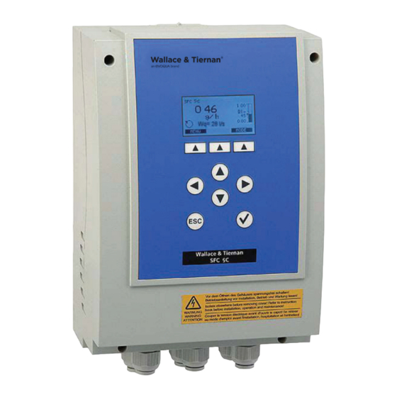
SfC-SC The SFC-SC is available in two voltage variations: • 100 to 240 VAC • 24 VDC 1.3.2 Design Overall Design The SFC-SC modules can be installed on a top-hat rail or using wall fasten- ing brackets. figure 1.1 - Electric module SfC-SC WT.050.590.002.UA.IM.0614 EVOQUA W3T109634... - Page 17 SFC ANALYZER / CONTROLLER SfC-SC Electronic Module The SFC-SC electronic module consists of a plastic housing with a removable cover. The housing contains: • IC board • The cable glands IC board Cable glands Housing figure 1.2 - SfC-SC Basic WT.050.590.002.UA.IM.0614 EVOQUA W3T109634...
- Page 18 SFC ANALYZER / CONTROLLER The following are integrated into the cover: • Front panel board with graphic display • Insertable nameplate strips Housing cover Front panel board Insertable strips figure 1.3 - SfC-SC operating front (rear) WT.050.590.002.UA.IM.0614 EVOQUA W3T109634...
- Page 20 Connecting SFC to Motor Controlled Actuators Used With 44 Series Metering Pumps ....50.590.130.050 Connecting SFC to Motor Controlled Actuators Used With Series 43-300 HATD Pumps ....50.590.130.060 Module Mounted SFC Controller V-2000 Module Mounted Gas Feeder ..... 50.590.130.070 WT.050.590.002.UA.IM.0614 EVOQUA W3T109634...
-
Page 21: Installation Wiring
Panel Mounted SFC Controller LVN-2000 Liquid Chemical Feed System ....50.590.130.110 Remote Mounted SFC Controller Without Junction Box - LVN-2000 Liquid Chemical Feed System ............50.590.130.120 Remote Mounted SFC Controller With Junction Box - LVN-2000 Liquid Chemical Feed System..............50.590.130.130 WT.050.590.002.UA.IM.0614 EVOQUA W3T109634... -
Page 22: Transport And Storage
Check that the transport packaging is undamaged. In the event of damage please inform the transport company immediately. If the device is damaged, please contact the respective Evoqua Water Technolo- gies agency immediately. Keep the packing until the unit has been correctly installed and put into operation. -
Page 23: Installation With Mounting Rail
Once the unit has been installed the electrical connections can be made. The following table contains the individual commissioning steps in their cor- rect sequence. Completion of each task can be confirmed in the "Completed" column. NOTE: If this installation sequence cannot be complied with, please contact you Evoqua Water Technologies service department. WT.050.590.002.UA.IM.0614 EVOQUA W3T109634... - Page 24 Check mA allocation, adjust if necessary (only if mA output is used) Check settings for digital inputs 1-2, adjust if necessary Via Mode-Man.Dos, check that all connected actuators and dosing pumps are working properly Switch to operating mode "Auto" WT.050.590.002.UA.IM.0614 EVOQUA W3T109634...
-
Page 25: Connect The Device To The Power Supply
1. Ensure that the cable bushes are fitted correctly. 2. Carefully fit the housing cover of the electronic module and secure with the four housing screws. Do not use power tools. Hand tighten only. Do not exceed 0.05lbs/ft (0.7N/m) torque. WT.050.590.002.UA.IM.0614 EVOQUA W3T109634... -
Page 26: Switching The Device On
Open the menu with the "Enter" key and set the required language using the up and down arrow keys. Then press "Enter" to confirm the selection. When the country language is set, this screen is no longer shown, unless the unit is reset to standard values. figure 2.1 - Basic display in main menu WT.050.590.002.UA.IM.0614 EVOQUA W3T109634... -
Page 27: Positioner Calibration
2.3.5 positioner Calibration If you are using a Evoqua Water Technologies positioner with feedback it is possible to linearize the control output, for example with a gas feeder. On a gas feeder, for example, 30% control opening does not always equal 30% dosing capacity. -
Page 28: Sfc-Sc Top Hat Rail Assembly
SFC ANALYZER / CONTROLLER SFC-SC TOP HAT RAIL ASSEMBLY - DIMENSIONS 50.590.100.070 ISSUE 0 1-09 WT.050.590.002.UA.IM.0614 EVOQUA W3T109634... -
Page 29: Sfc-Sc
SFC ANALYZER / CONTROLLER SFC-SC WALL MOUNT ASSEMBLY - DIMENSIONS 50.590.100.080 ISSUE 0 1-09 WT.050.590.002.UA.IM.0614 EVOQUA W3T109634... - Page 30 SFC ANALYZER / CONTROLLER Plug cable (included) Actuator SFC-SC - SCHEMATIC WIRING 50.590.155.020A ISSUE 2 10-11 WT.050.590.002.UA.IM.0614 EVOQUA W3T109634...
- Page 31 Connection of a dosing pump with contact closure signal 29 30 31 Connection of dosing pump with Connection of pulse triggered line voltage contact closure dosing pump with pulse contact SFC-SC- SCHEMATIC WIRING 50.590.155.020B ISSUE 1 10-11 WT.050.590.002.UA.IM.0614 EVOQUA W3T109634...
-
Page 32: Module Mounted Sfc-Sc Controller
SFC ANALYZER / CONTROLLER NOTE: WIRING BY EVOQUA WATER TECHNOLOGIES. MODULE MOUNTED SFC-SC CONTROLLER V-2000 MODULE MOUNTED GAS FEEDER - INSTALLATION WIRING 50.590.130.140 ISSUE 2 6-14 WT.050.590.002.UA.IM.0614 EVOQUA W3T109634... -
Page 33: Module Mounted Sfc-Sc Controller
SFC ANALYZER / CONTROLLER NOTE: WIRING BY EVOQUA WATER TECHNOLOGIES. MODULE MOUNTED SFC-SC CONTROLLER V-2000 MODULE MOUNTED GAS FEEDER - INSTALLATION WIRING 50.590.130.150 ISSUE 2 6-14 WT.050.590.002.UA.IM.0614 EVOQUA W3T109634... -
Page 34: Connecting Sfc To Motor Controlled Actuators
SFC ANALYZER / CONTROLLER NOTE: FIELD WIRING (NOT BY EVOQUA WATER TECHNOLOGIES) MUST CONFORM TO LOCAL ELECTRICAL CODES. POWER, L1/N AC, 100...125 VAC. L1/L2 AC, 220...240 VAC. CONNECTING SFC TO MOTOR CONTROLLED ACTUATORS - INSTALLATION WIRING Used with V10K and S10K Gas Feeders; Encore® 700 Series Metering Pumps; and LVN-2000 Liquid Chemical Feed System V-Notch - W2T11479 (115VAC); UXA96285 (230VAC) Pump - W3T108074 (115VAC); W3T108075 (230VAC) 50.590.130.010 ISSUE 3 6-14 WT.050.590.002.UA.IM.0614 EVOQUA W3T109634... - Page 35 SFC ANALYZER / CONTROLLER NOTES: FIELD WIRING (NOT BY EVOQUA WATER TECHNOLOGIES) MUST CONFORM TO LOCAL ELECTRICAL CODES. 2. RELEVANT INTERNAL FACTORY WIRING FOR W3T110034 ACTUATOR TERMINALS IS AS FOLLOWS: WIRE # TERMINAL 3. ACTUATOR KIT W3T124548 REQUIRED FOR PROPER SFC-SC RELAY OPERATION.
- Page 36 SFC ANALYZER / CONTROLLER NOTE: FIELD WIRING (NOT BY EVOQUA WATER TECHNOLOGIES) MUST CONFORM TO LOCAL ELECTRICAL CODES. POWER, L1/N, 100...125 VAC. L1/L2, 220...240 VAC. CONNECTING SFC TO PULSE CONTROLLED DEVICE - INSTALLATION WIRING 50.590.130.030 ISSUE 2 6-14 WT.050.590.002.UA.IM.0614 EVOQUA W3T109634...
- Page 37 SFC ANALYZER / CONTROLLER NOTES: FIELD WIRING (NOT BY EVOQUA WATER TECHNOLOGIES) MUST CONFORM TO LOCAL ELECTRICAL CODES. 2. RELEVANT INTERNAL FACTORY WIRING FOR U29202 ACTUATOR TERMINALS IS AS FOLLOWS: WIRE # TERMINAL 3. ACTUATOR KIT W3T124548 REQUIRED FOR PROPER SFC-SC RELAY OPERATION.
- Page 38 SFC ANALYZER / CONTROLLER NOTES: FIELD WIRING (NOT BY EVOQUA WATER TECHNOLOGIES) MUST CONFORM TO LOCAL ELECTRICAL CODES. 2. RELEVANT INTERNAL FACTORY WIRING FOR U27960 ACTUATOR TERMINALS IS AS FOLLOWS: WIRE # TERMINAL 3. ACTUATOR KIT W3T124548 REQUIRED FOR PROPER SFC-SC RELAY OPERATION.
- Page 39 SFC ANALYZER / CONTROLLER NOTE: FIELD WIRING (NOT BY EVOQUA WATER TECHNOLOGIES) MUST CONFORM TO LOCAL ELECTRICAL CODES. POWER, L1/N, 100...125 VAC L1/L2, 220...240 VAC CONNECTING SFC TO MOTOR CONTROLLED ACTUATORS - INSTALLATION WIRING Used with Series 43-300 HATD Pumps Pump - U28342 50.590.130.060 ISSUE 3 6-14 WT.050.590.002.UA.IM.0614 EVOQUA W3T109634...
- Page 40 SFC ANALYZER / CONTROLLER L1/N 100...125VAC L1/L2 220...240VAC NOTE: FIELD WIRING (NOT BY EVOQUA WATER TECHNOLOGIES) MUST CONFORM TO LOCAL ELECTRICAL CODES. MODULE MOUNTED SFC CONTROLLER V-2000 MODULE MOUNTED GAS FEEDER - INSTALLATION WIRING 50.590.130.070 ISSUE 2 6-14 WT.050.590.002.UA.IM.0614 EVOQUA W3T109634...
- Page 41 SFC ANALYZER / CONTROLLER NOTE: FIELD WIRING (NOT BY EVOQUA WATER TECHNOLOGIES) MUST CONFORM TO LOCAL ELECTRICAL CODES. POWER, L1/N, 100...125 VAC. L1/L2, 220...240 VAC. REMOTE MOUNTED SFC CONTROLLER V-2000 MODULE MOUNTED GAS FEEDER - INSTALLATION WIRING 50.590.130.080 ISSUE 2 6-14 WT.050.590.002.UA.IM.0614 EVOQUA W3T109634...
-
Page 42: Sfc Controller In Wall Mounted V-2000 Gas Feeder
SFC ANALYZER / CONTROLLER L1/N 100...125VAC L1/L2 220...240VAC NOTE: FIELD WIRING (NOT BY EVOQUA WATER TECHNOLOGIES) MUST CONFORM TO LOCAL ELECTRICAL CODES. SFC CONTROLLER IN WALL MOUNTED V-2000 GAS FEEDER - INSTALLATION WIRING 50.590.130.090 ISSUE 2 6-14 WT.050.590.002.UA.IM.0614 EVOQUA W3T109634... -
Page 43: Remote Mounted Sfc Controller V-2000 Wall Mounted Gas Feeder
SFC ANALYZER / CONTROLLER /N 100...125 VAC 220...240 VAC NOTE: FIELD WIRING (NOT BY EVOQUA WATER TECHNOLOGIES) MUST CONFORM TO LOCAL ELECTRICAL CODES. REMOTE MOUNTED SFC CONTROLLER V-2000 WALL MOUNTED GAS FEEDER - INSTALLATION WIRING 50.590.130.100 ISSUE 2 6-14 WT.050.590.002.UA.IM.0614 EVOQUA W3T109634... -
Page 44: Panel Mounted Sfc Controller Lvn-2000 Liquid Chemical Feed System
SFC ANALYZER / CONTROLLER L1/N 100...125 VAC L1/L2 220...240 VAC NOTE: FIELD WIRING (NOT BY EVOQUA WATER TECHNOLOGIES) MUST CONFORM TO LOCAL ELECTRICAL CODES. PANEL MOUNTED SFC CONTROLLER LVN-2000 LIQUID CHEMICAL FEED SYSTEM - INSTALLATION WIRING 50.590.130.110 ISSUE 2 6-14 WT.050.590.002.UA.IM.0614 EVOQUA W3T109634... -
Page 45: Remote Mounted Sfc Controller Without Junction Box - Lvn-2000 Liquid Chemical Feed System
SFC ANALYZER / CONTROLLER L1/N 100...125 VAC L1/L2 220...240 VAC NOTE: FIELD WIRING (NOT BY EVOQUA WATER TECHNOLOGIES) MUST CONFORM TO LOCAL ELECTRICAL CODES. REMOTE MOUNTED SFC CONTROLLER WITHOUT JUNCTION BOX LVN-2000 LIQUID CHEMICAL FEED SYSTEM - INSTALLATION WIRING 50.590.130.120 ISSUE 2 6-14 WT.050.590.002.UA.IM.0614 EVOQUA W3T109634... -
Page 46: Remote Mounted Sfc Controller With Junction Box - Lvn-2000 Liquid Chemical Feed System
SFC ANALYZER / CONTROLLER /N 100...125 VAC 220...240 VAC NOTE: FIELD WIRING (NOT BY EVOQUA WATER TECHNOLOGIES) MUST CONFORM TO LOCAL ELECTRICAL CODES. REMOTE MOUNTED SFC CONTROLLER WITH JUNCTION BOX LVN-2000 LIQUID CHEMICAL FEED SYSTEM - INSTALLATION WIRING 50.590.130.130 ISSUE 2 6-14 WT.050.590.002.UA.IM.0614 EVOQUA W3T109634... - Page 47 SFC ANALYZER / CONTROLLER WT.050.590.002.UA.IM.0614 EVOQUA W3T109634...
- Page 49 2-Point Pulse Frequency Controller for Pulse Pumps ............3.4.4 Analog Output Controller 2-Point ......... 3.4.5 Parameters and Settings ........... 3.5 Serial Port for Firmware Updates ........3.6 Actuator Feedback ............3.7 Digital Inputs ..............3.8 Unit Configuration ............3.9 WT.050.590.002.UA.IM.0614 EVOQUA W3T109634...
-
Page 50: General Information
The feed rate is determined on the basis of the flow rate signal and a user- configurable feed factor and output via a mA output or a relay. 3.1.2 Controller Outputs The system has controller outputs for positioners, dosing pumps, pulse pumps, and a continuous mA output. WT.050.590.002.UA.IM.0614 EVOQUA W3T109634... -
Page 51: Safety Functions
The relay contacts are protected by RC circuits prior to shipment. These provide radio interference suppression for inductive loads such as pumps, motors, etc. WT.050.590.002.UA.IM.0614 EVOQUA W3T109634... -
Page 52: Ratio Control
(external flow rate control signal) and a settable dosing factor. When actuators with feedback are used, any non-linearity of the dosing device can be adjusted using a maximum of 11 calibration points. WT.050.590.002.UA.IM.0614 EVOQUA W3T109634... - Page 53 SFC ANALYZER / CONTROLLER figure 3.2 - SfC-SC Summary of the inputs/outputs figure 3.3 - Sample application of the SfC-SC as ratio control Input signals: • Flow rate measurement (0/4 – 20mA) scalable The following dosing outputs are possible: • Dosing pump • Pulse pump • Positioner with feedback 1kOhm/5kOhm/0 –1 V/mA signal • mA analog output WT.050.590.002.UA.IM.0614 EVOQUA W3T109634...
- Page 54 D i = 1 0 0 % 1 0 0 % d o s i n g f a c t o r D i = 5 0 % 5 0 % 1 0 0 % figure 3.4 - Dosing factor WT.050.590.002.UA.IM.0614 EVOQUA W3T109634...
-
Page 55: Controller Outputs
Pulse pumps are controlled with 0 to 100 or 0 to 120 pulses per minute, depending on the specification of the connected pump. frequency controller WT.050.590.002.UA.IM.0614 EVOQUA W3T109634 for pulse pumps The duty cycle during each dosing is 0.3 s. The break time is... -
Page 56: Analog Output Controller 2-Point
NOTE: The control parameters are listed alphabetically. flow Rate Direction This parameter determines the direction of the flow rate signal directly proportional to the actuator output: Direct flow rate input signal directly proportional to positioner output (factory setting). Inverse 1 flow rate input signal WT.050.590.002.UA.IM.0614 EVOQUA W3T109634... - Page 57 Fast dosing pumps correspond to a low Tp; slow dosing pumps correspond to a high Tp. The control parameter Tp must always be adjusted to suit the pump em- ployed: Dosing pump up to 20 20-40 40-80 80-125 125-200 strokes/min Tp value WT.050.590.002.UA.IM.0614 EVOQUA W3T109634...
-
Page 58: Serial Port For Firmware Updates
1 kOhm. For other feedback signals the device must be reset using the DIP switch S4 (see IC board). Possible signals are: • Potentiometer 1 KOhm • Potentiometer 5 KOhm • 0/4–20mA signal • 0–1V signal WT.050.590.002.UA.IM.0614 EVOQUA W3T109634... -
Page 59: Digital Inputs
If the signal on the digital input is deactivated, then configuration 1 is loaded again and the SFC-SC continues to operate with the unit settings of Job 1. The digital input needs to be assigned to Job 2 in both configurations. WT.050.590.002.UA.IM.0614 EVOQUA W3T109634... - Page 60 SFC ANALYZER / CONTROLLER WT.050.590.002.UA.IM.0614 EVOQUA W3T109634...
- Page 62 Password ............... 4.2.1 Operation ..............4.2.2 Menu Structure ..............4.3 Main Menu ..............4.3.1 Menu Control ..............4.3.2 Menu Inputs/Outputs ........... 4.3.3 Menu System ..............4.3.4 Menu Diagnosis ............. 4.3.5 Menu Operating Mode ..........4.3.6 Errors ................4.4 WT.050.590.002.UA.IM.0614 EVOQUA W3T109634...
-
Page 63: Display And Operator Controls
The SFC-SC is operated with nine keys. The software function is controlled with the top three keys (softkeys). - 5 + figure 4.2 - Operating panel The exact depiction of the individual parameters on the graphic display is de- scribed in section 4.3, Menu Structure. WT.050.590.002.UA.IM.0614 EVOQUA W3T109634... - Page 64 “MANUAL” operating mode active Dosing can be set manually. “System stopped” operating mode S T O P Dosing is switched off. Bar graph This indicates a measured value of the measuring range (column height) and Di (internal dosing factor). WT.050.590.002.UA.IM.0614 EVOQUA W3T109634...
- Page 65 General messages This function is possible in the MANUAl mode only! This message appears, for example, if an at- tempt is made to calibrate the positioner during automatic operation. Acknowledge by pressing ENTER or the ESC key. WT.050.590.002.UA.IM.0614 EVOQUA W3T109634...
-
Page 66: Notes On Operation
This could damage the sealed keypad. 4.2.1 password The system is password protected to prevent unauthorized or incorrect operation. • The system password permits full access to all setting options. The password is a four-digit number combination. NOTE: The factory default is a null password (four zeros). If the password protection was not activated with the “lOCk” softkey after entry, the system is automatically locked one hour later. The password can be changed after correct entry of the existing password. WT.050.590.002.UA.IM.0614 EVOQUA W3T109634... -
Page 67: Operation
The "Mode" menu can be accessed directly from the main screen using the softkey. All other menus can be accessed with the "MENU" softkey. The following pages describe the individual menus. The diagrams show the factory default settings. WT.050.590.002.UA.IM.0614 EVOQUA W3T109634... -
Page 68: Main Menu
Bottom status line • Softkey display 4.3.2 Menu Control NOTE: The displayed menus and selection parameters depend on the current settings. All the parameters illustrated here are not displayed at the same time. Basic Display Refer to main menu. To access the control menu from the basic display press the "Menu" softkey. Selection Menu The SFC-SC will now display all available menus. WT.050.590.002.UA.IM.0614 EVOQUA W3T109634... -
Page 69: Menu Inputs/Outputs
Menu Select The SFC-SC will now display all available menus. Menu Inputs/Outputs Using the up and down arrows, move the curser to inputs/outputs menu and press enter. The SFC-SC will now display all input/output menus. WT.050.590.002.UA.IM.0614 EVOQUA W3T109634... -
Page 70: Menu System
If the DI is active, the controller output Yout is doubled. 4.3.4 Menu System Basic Display Refer to main menu. To access the system menu from the main display, press the menu softkey. Menu Select The SFC-SC will now display all available menus. WT.050.590.002.UA.IM.0614 EVOQUA W3T109634... - Page 71 The sample water delay (DI 1) determines the time after which dosing is deactivated, e.g. in the event of sample water stop. DI 1 flashes while the delay time is running. System restart This menu restarts the menu. Standard values Deletes customer settings, resets system to factory settings. WT.050.590.002.UA.IM.0614 EVOQUA W3T109634...
-
Page 72: Menu Diagnosis
The current circuit states of digital inputs 1 and 2 • The current input signal of the flow rate measurement (Wq) • Feedback signal display Software Version Diagnosis Displays the software version of the front panel boards and the IC boards. WT.050.590.002.UA.IM.0614 EVOQUA W3T109634... -
Page 73: Menu Operating Mode
MANUAl In MANUAL mode dosing is not automatically controlled. The values must be continuously monitored. MANUAL mode is used: • In the event of any possible system faults • During maintenance/cleaning work or while checking the system WT.050.590.002.UA.IM.0614 EVOQUA W3T109634... - Page 74 If several errors occur at the same time, the corresponding mes- sages appear alternately in succession. When the error has been remedied, the error message is automatically deleted. If you are unable to remedy the error yourself, please contact your local Evoqua Water Technologies service department. WT.050.590.002.UA.IM.0614...
- Page 75 Check (refer to section 2) rectly connected or defec- tive mA-Input 1 ? mA-Input signal has been Check mA connection or exceeded or fallen short of signal Ym display blink- Positioner disconnected Switch positioner to auto- matic WT.050.590.002.UA.IM.0614 EVOQUA W3T109634...
-
Page 76: Errors
Relay defective Check, replace IC board Positioner runs in Positioner incorrectly con- Correct connections wrong direction nected Positioner closes Positioner feedback inter- Correct connections rupted Digital outputs Digital inputs not activated Activate digital inputs without function WT.050.590.002.UA.IM.0614 EVOQUA W3T109634... - Page 77 SFC ANALYZER / CONTROLLER WT.050.590.002.UA.IM.0614 EVOQUA W3T109634...
- Page 79 SFC ANALYZER / CONTROLLER SECTION 5 - MAINTENANCE list of Contents PARA. NO. Changing the Fuse on the IC Board ........5.1 WT.050.590.002.UA.IM.0614 EVOQUA W3T109634...
- Page 80 1. Disconnect the device from the power supply. 2. Remove the cover of the electronic module. 3. Remove screw-in fuse holder 4. Change the defective fuse. 5. Screw the screw-in fuse holder back in. 6. Reassemble the device. Screw-in fuse holder figure 5.1 - Cutaway model of fuses WT.050.590.002.UA.IM.0614 EVOQUA W3T109634...
- Page 82 SFC ANALYZER / CONTROLLER SECTION 6 - SpARE pARTS list of Contents PARA. NO. Complete Unit ..............6.1 SFC-SC Spare Parts ............6.2 WT.050.590.002.UA.IM.0614 EVOQUA W3T109634...
- Page 83 Connection cable IC board front panel board approx. 0.5 m W2T350529 IC board fuse for 24 V DC and 100 – 240 V AC (1A time-lag) W2T350536 Update cable for SFC with 9 pin RS232-DSUB connector W2T320242 WT.050.590.002.UA.IM.0614 EVOQUA W3T109634...
Need help?
Do you have a question about the Wallace & Tiernan SFC-SC and is the answer not in the manual?
Questions and answers