Table of Contents
Advertisement
Advertisement
Table of Contents

Subscribe to Our Youtube Channel
Related Manuals for Evoqua WALLACE & TIERNAN SFC BA W3T166501


Summary of Contents for Evoqua WALLACE & TIERNAN SFC BA W3T166501
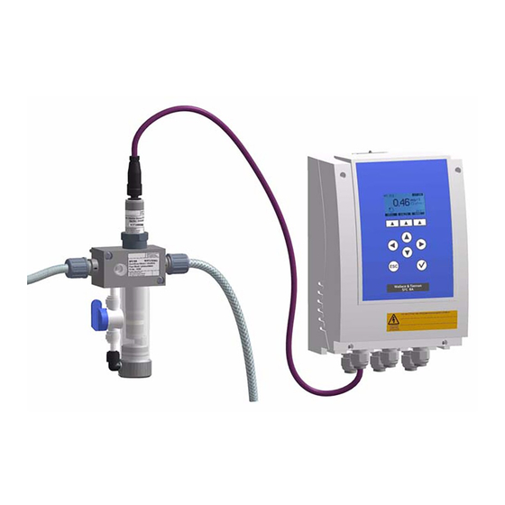
- Page 1 ® WALLACE & TIERNAN MEASURING SYSTEM SFC BA INSTRUCTION MANUAL...
- Page 2 SFC BA Please note Original instruction manual! WT.050.590.030.IM.DE.0719...
-
Page 3: Table Of Contents
SFC BA Contents Contents Introduction Documentation Conventions Safety Intended use General safety instructions Warranty conditions Specific Operating Phases Notes on Special Dangers Description Versions Technical Data Scope of supply Description System configuration Functions General Outputs Alarms CAN interface Firmware Update Digital inputs SD memory card System configuration... - Page 4 SFC BA Contents Operation Display and operator controls Notes on operation Menu structure Calibration Errors and remedies Maintenance Maintenance Schedules CAN membrane sensor maintenance Changing the fuse on the A&C board Replacing the battery Complete Systems, Retrofit Kits and Spare Parts Wiring Diagram 10.
-
Page 5: Introduction
SFC BA Introduction 1. Introduction Documentation 1.1.1 Target groups This operating manual provides the information for installation, operating and maintenance personnel. It is required for operation and maintenance of the system. This operating manual is intended for the operating personnel. It contains important information for safe, reliable, trouble-free and economical operation of the system. -
Page 6: Conventions
SFC BA Introduction Conventions Please note This operating manual contains a number of notes with different priorities, which are marked with symbols. Symbol Caption Meaning Immediate danger to life and limb! If Danger! the situation is not handled properly, death or serious injury may be the result. -
Page 7: Safety
General safety instructions Evoqua attaches great importance to ensuring that work on its system is always perfectly safe. This has been taken into account in the design of the system, by the integration of safety features. -
Page 8: Warranty Conditions
"Authorized specialized personnel" refers to trained technicians employed by the operator, Evoqua or, if applicable, the service partner. Only qualified electricians may perform work on electrical components. Trouble-free operation of the system is only guaranteed if original... -
Page 9: Specific Operating Phases
SFC BA Safety • An operating log book must be kept (only in the public sector). • The system must not be exposed to frost. • Maintenance work must be carried out. • Use of original spare parts. If any of the above conditions are not met, the warranty is void. Specific Operating Phases Never employ any working methods which could affect safety! Normal operation... -
Page 10: Notes On Special Dangers
SFC BA Safety Notes on Special Dangers Only use original fuses with the prescribed current rating! In the Electrical power event of a fault in the electrical power supply, switch the system off immediately! Only qualified electricians or trained personnel supervised by a qualified electrician are permitted to perform any work on electrical components in accordance with valid electro-technical regulations. -
Page 11: Description
SFC BA Description 3. Description Versions The SFC BA is available as standard wall-mounted system. It has the following inputs and outputs: • 2 relays • 1x digital input • 1x mA output • 1x CAN interface for connecting the sensor •... - Page 12 SFC BA Description Insulation Overvoltage category Contamination level Measuring category Attention! Do not use the system in measuring categories II, III and IV. Operating conditions Ambient temperature 0 – 50 °C Humidity < 80 % Environment No direct sunlight Atmospheric pressure 75 –...
- Page 13 SFC BA Description mA output 1x mA output: • Output 0/4 – 20 mA • Accuracy < 0.5% FS • Load max. 500 Ohm • Temperature drift max. 0.2% / 10°C • Load monitoring • Electrically isolated up to 50 V to earth 3.2.2 SFC BA flow cell module Picture 1...
-
Page 14: Scope Of Supply
SFC BA Description Flow rate Flow rate* Approx. 10 – 15 l/h (Can be set using the flow control valve) Pressure range 0.2 - 4.0 bar Back pressure Non-pressurized version (gravity drain) Sample water Water quality Drinking water, swimming pool water Sample water temperature max. -
Page 15: Description
SFC BA Description Description 3.4.1 Versions There are two voltage versions of the SFC BA. SFC BA • 100 – 240 V AC • 24 V DC System configuration The SFC BA electronics module can be installed on a DIN rail or Overall design using wall fastening brackets. - Page 16 SFC BA Description The electronics module SFC BA consists of a plastic housing (C) Electronics module SFC BA with a removable cover. The housing contains: • A&C board (A) • the cable glands (B) Picture 3 SFC BA Basic A A&C Board B Cable glands C Enclosure WT.050.590.030.IM.DE.0719...
- Page 17 SFC BA Description The following are integrated into the cover: • Front panel board with graphic display (B) • Insertable strips (C) Picture 4 SFC BA Operating front (rear) A Housing cover B Front panel board C Insertable strips...
- Page 18 SFC BA Description SFC BA flow cell module The SFC BA flow cell module with integrated sensor ensures Non-pressurized version optimum flow over the sensors due to its special design. The SFC BA flow cell module guarantees a stable measurement signal combined with low water consumption of just 10 –...
-
Page 19: Functions
SFC BA Functions 4. Functions General The SFC BA is a special measuring instrument for use in drinking water treatment as well as for industrial process and swimming pool water treatment. A typical application is: • Measurement and recording of water parameters Potential process measurements include: •... - Page 20 SFC BA Functions Potential parameters include: Total function • Total chlorine* (CAN membrane sensor) • Free chlorine* (CAN membrane sensor) * These measurements are automatically temperature-compensated. • The SFC BA has an integrated CAN interface. This is used to CAN interface exchange data with CAN-capable sensors (for a description and bus design, see 4.4 “CAN interface”).
- Page 21 SFC BA Functions Ambient conditions Installation notes The following factors need to be taken into account when installing the CAN membrane sensors: • Select the sample water extraction point that guarantees a proper mixture of disinfectant and a bubble-free sample water flow.
- Page 22 SFC BA Functions The membrane sensors FC1-CAN and FC2-BA CAN are special Membrane sensor for sensors for measuring the concentration of free chlorine in water. free chlorine FC1-CAN / The sensor demonstrates a slight pH value dependency (see FC2-BA CAN "Technical data"...
- Page 23 SFC BA Functions 6 Hold the electrode shaft (B) vertically and carefully push the electrode finger (D) into the filled G-holder (K) (not for FC2-BA CAN). 7 Wet the thread of the electrode shaft with electrolyte. 8 Then screw the filled membrane cap (E) slowly (by hand) back onto the electrode shaft (B).
- Page 24 SFC BA Functions 4 Leave the membrane cap (E) to dry in a dust-free place. 5 Screw the dry membrane cap (E) loosely onto the electrode shaft (B). 6 Place G-holder (K) loosely into the membrane cap (E), do not fit onto the electrode finger (D) (not for FC2-BA CAN).
- Page 25 SFC BA Functions The membrane sensor TC1-CAN measures the total amount of Membrane sensor for free and combined chlorine (chloramine). The sensor free chlorine TC1-CAN demonstrates a slight pH value dependency (see "Technical data") and is therefore very suitable for water with variable pH values.
- Page 26 SFC BA Functions 8 Rinse off the electrolyte that overflowed with water. Please note The membrane cap (E) must be completely screwed (hand-tight) onto the electrode shaft (B), so that no gap remains between the two! After a run-in period of about one hour, the membrane sensor is sufficiently run-in for an initial calibration to take place.
- Page 27 SFC BA Functions 1 Remove air bubbles on the membrane (G) by lifting the Troubleshooting and debugging membrane sensor; air bubbles prevent the chlorine from when the measuring signal is diffusing through the membrane (G) and distort the too low measurement! or irregular Please note...
-
Page 28: Outputs
SFC BA Functions Outputs 4.2.1 mA output The mA output of the SFC BA is electrically isolated and can be parameterized to 0 – 5 mA, 0 – 10 mA, 0 – 20 mA or 4 – 20 mA in the menu. -
Page 29: Alarms
SFC BA Functions Alarms The output of both of the alarms takes place by means of relay contacts and alarm indicators on the display. Each alarm can be assigned the following functions: • Limit value = Min Measured values freely selectable •... - Page 30 SFC BA Functions In the event of an alarm, the alarm symbol on the display flashes Latched alarm with until the alarm is acknowledged. The LED also goes out even if the reset-acknowledgement option alarm conditions still apply when the alarm is acknowledged. (N.O.
-
Page 31: Can Interface
SFC BA Functions CAN interface The CAN interface is used to connect the system to the CAN membrane sensor: The CAN interface of the SFC BA is not electrically isolated. To connect the CAN sensor, the SFC BA has three terminals as well as a terminating resistor Rt and the balancing resistors Ru and Rd. -
Page 32: Firmware Update
SFC BA. A special software download and the latest firmware including a description is available from the homepage www.evoqua.com. A special update cable is available for the firmware update under part no. W3T164902. It is possible to perform a software update of the SFC BA (front... - Page 33 SFC BA Functions Firmware Update Loading Bootloader !! Warning !! Do NOT turn off the device or put out the SD-card during the firmware update! CANCEL To start the update, confirm this display with "OK" key. Check Flash Check Firmware Firmware found:...
-
Page 34: Digital Inputs
SFC BA Functions Digital inputs One digital input is integrated in the SFC BA's A&C board. This input is provided for connecting voltage-free contacts (< 100 Ohm) and has an internal 12 V power supply. Warning! Do not apply a voltage to the digital input terminal! SD memory card Warning! Only insert/remove the-SD memory card when the power supply... - Page 35 SFC BA Functions Example of a file section Date MW-mg/l Temperature 2008-01-01 00:01 0.21 19.1 2008-01-01 00:02 0.21 19.1 2008-01-01 00:03 0.22 19.1 Picture 6 shows the installed SD-card A SD-card Please note Files ending with "*.Bin" can not be evaluated. They are only used as data storage for the SFC BA and must not be altered.
-
Page 36: System Configuration
SFC BA Functions System configuration The SFC BA gives the option of saving all system settings as a configuration. System settings include all parameters that can be set in the menu, such as the measuring range, limit values, etc). A maximum of two configurations can be saved in the internal memory SFC BA (see Menu-System-Configuration-Save-Job 1, Job 2). -
Page 37: Installation
SFC BA Installation 5. Installation Transport and storage The system is supplied in standard packaging. During transport Transport the packaged system must be handled carefully and should not be exposed to wet weather or moisture. Check that the transport packaging is undamaged. In the event of damage please inform the transport company immediately, as your rights to compensation will otherwise be lost. -
Page 38: Installation
SFC BA Installation Installation 5.2.1 SFC BA electronics module The system must be protected against rain, frost and direct Installation site sunlight and may therefore not be installed outdoors. It must be mounted horizontally on a flat wall in a frost-free room with an ambient temperature of 0 to 50 °C. - Page 39 SFC BA Installation 5.2.2 SFC BA flow cell module 1 Mount the SFC BA flow cell module with mounting set W3T167661 (2 screws, 2 washers, 2 S8 dowels ) provided. Please note Observe the 300 mm of space required above the system for changing the sensor!...
- Page 40 SFC BA Installation Installation of the electronics module wall mounting 3,620" 3,620" 3,071" 3,071" 5,600" 6,142" 0,140" min. min. 2" BZ-1550.006 / ISSUE 2 22-APR-08 / TZ 7 ½" WT.050.590.030.IM.DE.0719...
- Page 41 SFC BA Installation Installation of the electronics module on a top-hat rail 3,620" 3,620" 6" 3,071" 3,071" 5,600" 6,142" min. min. 2" BZ-1550.005 / ISSUE 2 22-APR-08 / TZ 7 ¼" A Optional mounting rail for mounting the SFC BA on a top-hat rail, Part No.
- Page 42 SFC BA Installation Installation of the flow cell module wall mounting WT.050.590.030.IM.DE.0719...
-
Page 43: Start-Up
SFC BA Installation Start-up 5.3.1 Start-up guide Once the system has been installed the electrical connections can Start-up procedure be made. The following table contains the individual start-up steps in their correct sequence. More detailed information is contained in the chapters listed in the "Chapter and page reference"... - Page 44 SFC BA Installation Start-up Ser. Chapter and Compl Task page reference eted Connect electrical connection 5.3.4 Connect the sensor 5.3.2 Close the housing cover 5.3.5 Switch the system on 5.3.6 Set the language 5.3.6 Set the time Page 72 Set the date Page 72 Enter system name Page 72...
- Page 45 SFC BA Installation 5.3.2 Inserting and connecting the membrane sensor Please note Please refer to the CAN membrane sensor data sheets for details. See 4.1.1 “CAN membrane sensors”. A Remove the protective cap (A). B Push the membrane sensor through the locking screw (C) into the flow cell module until it is in physical contact with the flow body (B).
- Page 46 SFC BA Installation 5.3.3 Connecting the Sample Water A Sample water inlet B Sample water outlet, non-pressurized Connecting the sample water inlet Please note Never use copper tubing. 1 The pressure in the sample water inlet must always be within a range of min.
- Page 47 SFC BA Installation 3 An external strainer with a mesh width of 0.5 mm is provided for the sample water inlet. (e.g. part no. W3T158522, with a G1/2" hose connector on both sides). Please note Inspect the sample water flow rate at least once daily and adjust to approx.
- Page 48 SFC BA Installation Picture 1 Locking ring for PE hose with 3 clamping points Picture 2 Locking ring for PVC hose with 2 clamping points 1 Connect the sample water pipes to the threaded connection With rigid pipes (G1/2") on the sample water inlet. 2 Ensure that the sample water pipes are installed so that it is free of mechanical stress.
- Page 49 SFC BA Installation Examples of sample water extraction system W2T505525 W2T505525 W3T167656: 0.1 – 1 bar W3T167645: 4 – 16 bar W3T167628: 0.15 – 4 bar Item Part No. Description W2T506486 Pressure gauge bushing W3T167416 Sample pipe W3T171391 Strainer DN15 W3T161902 Ball valve R 1/2"...
- Page 50 SFC BA Installation Examples of sample water extraction using a booster pump Example 1 WT.050.590.030.IM.DE.0719...
- Page 51 SFC BA Installation Example 2...
- Page 52 SFC BA Installation Sample water extraction for fresh water part no. W3T158528 Parts list Sample water extraction for salt water part No. W3T158529 Ser. Part No. Description Quantity W2T505181 Screw connection W2T505182 Screw connection W3T171416 Strainer complete W3T167518 Hose connection parts W3T173160...
- Page 53 SFC BA Installation 5.3.4 Connecting the system to the power supply Warning! Only authorized and qualified electricians are permitted to install the system and open the housing. The system may only be put into operation when the housing is closed, and must be connected to protection earth.
- Page 54 SFC BA Installation 5.3.5 Mounting the housing covers 1 Ensure that the cable bushes are fitted correctly. 2 Carefully fit the housing cover of the electronic module and secure with the four housing screws. Please note Tighten the housing screws to a maximum torque of 0.7 Nm (±...
-
Page 55: Shut-Down
SFC BA Installation Shut-down Attention! If the installation site of the flow cell module is not frost-free, the system must be shut down in due time! 1 Switch off the power supply. 2 Drain the sample water supply line and drainage line. (Hold a container under it). - Page 56 SFC BA Installation WT.050.590.030.IM.DE.0719...
-
Page 57: Operation
SFC BA Operation 6. Operation Display and operator controls All information is shown on the graphic display. Graphic display and operating panel SFC-BA 0.25 1.00 0.00 mA-output ? 1/01 MENU Picture 1 Graphic display The SFC BA is operated using nine keys. The software function is controlled with the top three keys (softkeys). - Page 58 SFC BA Operation Indicators System name (Entered under "System" - "Common" - "System Analyzer 1 name") DI Digital input 1 active The symbols indicate that a function has been selected for the digital signal and that a signal is applied (= digital input open). Password active...
- Page 59 SFC BA Operation 83.12? Sample water temperature Error message active (display bottom right) The system has detected an error. The error can be identified using the table in chapter 6.5 “Errors and remedies”. The number combination states the series number of the error message and the total number of error messages (in this example: 1.
- Page 60 SFC BA Operation Operator controls Softkey • Activate the function shown on the graphic display over the keys. • Move up one level. • Display the previous option. • Increase value. Down • Move down one level. • Display the next option. •...
-
Page 61: Notes On Operation
SFC BA Operation Notes on operation During operation observe the following points: • Check your entries and modifications before exiting the menu. • Only press the keys with your fingers, never with hard or pointed objects such as pencils, etc. This could damage the sealed keypad. - Page 62 SFC BA Operation You have the following options starting from the basic display (the Operation basic display is opened by pressing the "ESC" key in the menu four times): Switch between the • Press the up or down key basic displays and trend graphs Select menu •...
-
Page 63: Menu Structure
SFC BA Operation Menu structure The SFC BA has various menus: • Main menu • Module type, e.g. Cl free (M) • Inputs/Outputs • Alarms • System • Diagnosis • Calibration The "Calibration" menu can be accessed directly from the basic display using the appropriate softkeys. - Page 64 SFC BA Operation Main menu Basic display 1 SFC-BA 0.25 1.00 0.00 mA-output ? 1/01 MENU BACK Trend Graph 1 mg/l Cl free 1.00 0.50 0.00 MENU BACK Trend Graph 2 °C Temperature 50.0 25.0 MENU Top status line Basic display 1 •...
- Page 65 SFC BA Operation Top status line Line diagrams (2 max.) • Unit and type of the selected measurement parameter • Date of the displayed diagram Centre display range • Six hours line graph (scroll back up to 30 days with option SD memory card) Bottom line •...
- Page 66 SFC BA Operation Display based on a free chlorine measurement example Menu - Module type SFC-BA 1.00 0.25 Basic display 0.00 MENU BACK Menu Select BACK ENTER Menu Sensortype BACK ENTER Measuring Range BACK ENTER Limit Values WT.050.590.030.IM.DE.0719...
- Page 67 SFC BA Operation Menu - Module type Refer to main menu Basic display Display of all available menus Menu Select Displays all of the settings available for the current sensor type Menu Sensortype Changing the measuring range Measuring Range 100 / 200 / 500 µg/l 1,00 / 2,00 / 5,00 / 10,0 mg/l Unit mg/l, µg/l...
- Page 68 SFC BA Operation Menu - Inputs/Outputs SFC-BA Basic display 1.00 0.25 0.00 MENU BACK Menu Select BACK ENTER Menu Inputs/Outputs BACK ENTER Analog out BACK ENTER Digital Inputs WT.050.590.030.IM.DE.0719...
- Page 69 SFC BA Operation Menu - Inputs/Outputs Refer to main menu Basic display Display of all available menus Menu Select Display of all available input/output settings Menu Inputs/Outputs Analog out 0 – 5 mA, 0 – 20 mA, 4 – 20 mA, mA signal 0 –...
- Page 70 SFC BA Operation Menu - Alarm Basic display SFC-BA 1.00 0.25 0.00 MENU BACK Menu Select BACK ENTER Menu Alarms BACK Alarm 1/2 function ENTER BACK Alarm assign ENTER WT.050.590.030.IM.DE.0719...
- Page 71 SFC BA Operation Menu - Alarms Refer to main menu Basic display Display of all available menus Menu Select Display of all available settings Menu Alarms Alarm 1/2 function Alarm 1 function Defines the contact condition of the alarm relay, if the alarm is not active. N.O.unlatched...
- Page 72 SFC BA Operation Menu - System Basic display SFC-BA 1.00 0.25 0.00 MENU BACK Menu Select BACK ENTER Menu System BACK ENTER General BACK ENTER Configuration BACK ENTER Safety BACK ENTER Trend Graph BACK ENTER Firmware Update BACK ENTER System Reset WT.050.590.030.IM.DE.0719...
- Page 73 SFC BA Operation Menu - System Refer to main menu Basic display Display of all available menus Menu Select Display of all available system settings Menu System General Time (hh:mm) Current time Date (dd.mm.yy) Current date Off / low / high Measure.filter Hold function Off/On...
- Page 74 SFC BA Operation Safety System password four-digit numeric code (activate with Softkey "LOCK" in the "Menu Select" window) Calibration four-digit numeric code password* (activate with Softkey "LOCK" in the "Menu Select" window) * only if system password is set Trend Graph Channels 1 to 2 Assignment of a measured value to the trend graph.
- Page 75 SFC BA Operation Menu Diagnosis SFC-BA Basic display 1.00 0.25 0.00 MENU BACK Menu Select BACK ENTER Menu Diagnosis BACK ENTER Diagn. Sensortype (1) act. 8.1nA BACK ENTER Diagnosis I/O BACK ENTER Maintenance interval BACK ENTER Software Version...
- Page 76 SFC BA Operation Menu Diagnosis Refer to main menu Basic display Display of all available menus Menu Select Display of all available diagnosis displays Diagnosis Scroll by pressing the "-->" softkey Diagnosis Sensortype taking Cl as an example Date and time of the last 5 calibrations Calibration data CAN membrane sensor Cl tot, Cl free...
- Page 77 SFC BA Operation Information about the Maintenance Interval for the membrane Maintenance Interval sensor • days remaining to change the electrolyte • days remaining to change the membrane cap If the "Maintenance?" warning message is shown in the main display the Diagnosis menu informs you about the necessary maintenance (in the example the electrolyte)....
- Page 78 SFC BA Operation Menu - Calibration Basic display SFC-BA 1.00 0.25 0.00 MENU BACK Calibration BACK ENTER Sensor type calibration (for example, Cl free) BACK ENTER 0.56 +2.4nA BACK ENTER Temperature calibration BACK ENTER 23.8 23.8°C WT.050.590.030.IM.DE.0719...
- Page 79 SFC BA Operation Refer to 6.4 “Calibration”. Menu - Calibration Refer to main menu Basic display Display of all available calibration options Calibration Module type calibration Zero / Span within measuring range CAN membrane sensors Cl free Calib.Span within measuring range Calibration mode 1-point/2-point CAN membranesensor...
-
Page 80: Calibration
SFC BA Operation Calibration Attention! The electrode fingers or membranes on the sensors are extremely sensitive! Do not touch, soil or damage them. Attention! Note the safety data sheets for buffer solutions. Please note To prevent any unwanted control signals being emitted during calibration, the "Hold"... - Page 81 SFC BA Operation 6.4.2 CAN membrane sensor calibration The calibration process is almost identical for all types of CAN membrane sensor. The difference lies in the fact that some of the chemicals are measured manually with a photometer and others with a colour meter....
- Page 82 SFC BA Operation Zero point calibration using 2-point calibration Zero point calibration for Cl free Please note Instead of the zero point, a span value can also be calibrated. 1 Starting from the basic display, select the "Calibration" menu. 2 Select the measurement to be calibrated from the menu, e.g. free (M) and press "ENTER"...
-
Page 83: Errors And Remedies
SFC BA Operation Errors and remedies The following table shows and explains all possible error Error messages messages which can be displayed. If several errors occur at the same time, the corresponding messages appear alternately in succession. Once the error has been corrected, the error message is automatically deleted. - Page 84 SFC BA Operation Error message Cause Remedy Maintenance? Maintenance of probe required Check whether the maintenance of electrolyte or membrane cap has to be performed in the menu Diagnosis. Perform the maintenance and reset the interval like in the description of the menu Diagnosis.
- Page 85 SFC BA Operation Errors SFC BA flow cell module Please note The following table shows and explains possible errors which can occur. If you are unable to remedy the error yourself, please contact your contractual partner. Error Cause Remedy Insufficient flow rate of Outlet of flow control valve Raise the flow rate with the flow control sample water...
- Page 86 SFC BA Operation WT.050.590.030.IM.DE.0719...
-
Page 87: Maintenance
SFC BA Maintenance 7. Maintenance Maintenance Schedules Please note The following maintenance schedules are recommendations only. Adhere to the appropriate standards, regulations and locally applicable guidelines. Activity Period/Interval Page SFC BA flow cell module Check for leakages daily Page 87 Comparative measurement, calibrate if necessary daily/acc. -
Page 88: Can Membrane Sensor Maintenance
SFC BA Maintenance CAN membrane sensor maintenance For details of the membrane sensor maintenance procedure, see 4.1.1 “CAN membrane sensors”. Changing the fuse on the A&C board Warning! Only authorized and qualified electricians are permitted to open the housing. The system is not equipped with a mains switch. -
Page 89: Replacing The Battery
SFC BA Maintenance Replacing the battery Warning! Only authorized and qualified electricians are permitted to open the housing. The system is not equipped with a mains switch. The buffer battery is required for the real time clock in case of a power failure. - Page 90 SFC BA Maintenance WT.050.590.030.IM.DE.0719...
-
Page 91: Complete Systems, Retrofit Kits And Spare Parts
SFC BA Complete Systems, Retrofit Kits and Spare Parts 8. Complete Systems, Retrofit Kits and Spare Parts Warning! For reasons of safety, only use original spare parts. Please contact our customer service department if you need any spare parts. SFC BA electronics module Part No. - Page 92 SFC BA Complete Systems, Retrofit Kits and Spare Parts SFC BA spare parts Part No. Designation W3T166505 Spare circuit board A&C board SFC BA 100 – 240 V AC W3T166506 Spare circuit board A&C board SFC BA 24 V DC W3T158821 Front control panelSFC BA W3T158866...
- Page 93 SFC BA Complete Systems, Retrofit Kits and Spare Parts SFC BA flow cell module Spare parts Item Part No. Designation W3T169084 Ball bearing W3T170363 Flow control valve W3T172468 Male elbow connector W3T172469 Stop valve W2T505784 Hose 100 mm W3T168401 O-ring W3T169071 O-ring* W3T169011...
- Page 94 SFC BA Complete Systems, Retrofit Kits and Spare Parts Unplug the connectors and then reconnect (Item Nos. 8–10) Please note The plug connectors do not require any tools to connect/ disconnect. 1 Check that the system is unpressurized. Unplug the connector 2 Then the elbow (Item No.
-
Page 95: Wiring Diagram
18.11.09 Date 07.10.09 Design Center LAE5900.010 13.05.14 Drawn Prod. / Sales SFC-BA LAE7029.002 03.07.19 Date Date Checked release Issue Revision Date Name Norm Urspr. Ers. f. Ers. d. Project SFC-BA Evoqua Water Technologies GmbH order number Drawing number Sheet 8667... - Page 96 SFC BA Wiring Diagram WT.050.590.030.IM.DE.0719...
-
Page 97: 10.Index
SFC BA Index 10.Index Error messages 83 A&C Board Remedy 83 Replacing the fuse 88 Alarm Menu 70 Alarms 29 Firmware Update 32 Functions 19 Fuse replace 88 Basic display 1 64 General 19 Calibration 80 General messages 59 CAN membrane sensors 81 General status messages 59 Combined chlorine 81 Graphic display 57... - Page 98 SFC BA Index Module type Shut-down 55 Menu 66 Softkeys 58 Menu Select 67 Spare parts 91 Standard values 74 Start-up 43 Storage 37 Notes on operation 61 Switching on Device 54 System Menu 72 Opening the housing 38 System restart 74 Operating panel 57 System settings Operation 57...
- Page 99 ® Wallace & Tiernan Products worldwide Australia Canada China +61 1300 661 809 +1 905 944 2800 +86 21 5118 3777 info.au@evoqua.com wtoe.can@evoqua.com sales.cn@evoqua.com France Germany Singapore +33 1 41 15 92 20 +49 8221 9040 +65 6559 2600 wtfra@evoqua.com wtger@evoqua.com...
- Page 100 All information presented herein is believed reliable and in accordance with accepted engineering practices. Evoqua makes no warranties as to the completeness of this information. Users are responsible for evaluating individual product suitability for specific applications. Evoqua assumes no liability whatsoever for any special, indirect or consequential damages arising from the sale, resale or misuse of its products.
Need help?
Do you have a question about the WALLACE & TIERNAN SFC BA W3T166501 and is the answer not in the manual?
Questions and answers