Table of Contents
Advertisement
Advertisement
Table of Contents

Related Manuals for Evoqua WALLACE & TIERNAN DEPOLOX 5 E


Summary of Contents for Evoqua WALLACE & TIERNAN DEPOLOX 5 E
- Page 1 ® ® WALLACE & TIERNAN DEPOLOX FLOW CELL INSTRUCTION MANUAL...
- Page 2 DEPOLOX ® 5 E flow cell Please note Original instruction manual! Simone WT.050.810.040.DE.IM.0817...
-
Page 3: Table Of Contents
DEPOLOX 5 E flow cell ® Contents Contents Introduction Documentation Conventions Disclaimer Safety Intended use General safety instructions Specific operating phases Warranty conditions Description General Versions Design and functions Optional accessories Technical Data Installation Scope of supply Transport and storage Ambient conditions Mechanical installation Commissioning... - Page 4 DEPOLOX 5 E flow cell ® Contents Maintenance Maintenance intervals Maintenance parts kit Checking for leakage Checking electrode cleaning sand Checking electrolyte solution level Checking diaphragms Replacing or cleaning electrode cleaning sand, electrolyte solution, reference electrode and diaphragms Cleaning or replacing the fine filter Cleaning flow rate monitor and check valve 5.10 Cleaning...
-
Page 5: Introduction
DEPOLOX 5 E flow cell ® Introduction 1. Introduction Documentation 1.1.1 Target groups This instruction manual provides the information for installation, operating and maintenance personnel. It is required for operation ® and maintenance of the DEPOLOX 5 E flow cell (module type D01). -
Page 6: Conventions
DEPOLOX 5 E flow cell ® Introduction Conventions Please note This instruction manual contains notes with different priorities that are marked with symbols. Please Pictogram Meaning note Danger! Immediate danger to life and limb! If the situation is not corrected, death or serious injury will result. -
Page 7: Disclaimer
DEPOLOX 5 E flow cell ® Introduction Disclaimer We are not liable for any damages incurred during installation or use of these hardware and software components. This applies specifically to trouble-free interaction with the software and hardware components you choose. We are not liable for buyer damages (in particular, lost profits, lost information and service interruptions), which arise when using the ®... - Page 8 DEPOLOX 5 E flow cell ® Introduction WT.050.810.040.DE.IM.0817...
-
Page 9: Safety
DEPOLOX 5 E flow cell ® Safety 2. Safety Intended use ® The DEPOLOX 5 E flow cell (module type D01) in combination with the installed sensors and the 700 P electronics module (module type E01) or 700 M electronics module (module type E01) is intended only for measurement and control in the treatment of drinking water, process water, industrial water, wastewater, and swimming and bathing pool water. -
Page 10: General Safety Instructions
DEPOLOX 5 E flow cell ® Safety General safety instructions The manufacturer places great value upon safety when working with the unit. This was already taken into account in the design of the system, by the integration of safety features. Safety regulations The safety instructions in this documentation must be observed. -
Page 11: Specific Operating Phases
DEPOLOX 5 E flow cell ® Safety IT security The manufacturer offers IT security mechanisms for its products to support secure system operation. We recommend checking on a regular basis to see what information is available regarding IT security developments for your products. Information on this can be found on the Internet. -
Page 12: Warranty Conditions
DEPOLOX 5 E flow cell ® Safety Warranty conditions The following must be observed for compliance with warranty conditions: • Installation and commissioning by the manufacturer or trained and authorized specialists, e.g. of contractors • Intended use • Observation of the operational parameters and settings. •... -
Page 13: Description
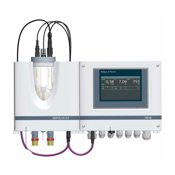
® DEPOLOX 5 E flow cell Description 3. Description General ® The DEPOLOX 5 E flow cell (module type D01) is part of the Pool ® Management System DEPOLOX 5 E 700 P and the measuring ® and control unit DEPOLOX 5 E 700 M. -
Page 14: Versions
® DEPOLOX 5 E flow cell Description ® DEPOLOX 5 E flow cell is available in both a non-pressurized and a pressurized version. The two versions differ in the number of sensors that can be installed and in the design of the sample water outlet. - Page 15 ® DEPOLOX 5 E flow cell Description ® 3.2.1 Pool Management System DEPOLOX 5 E 700 P ® The DEPOLOX 5 E flow cell (module type D01) is factory-config- ured according to the customer’s specific requirements with the 700 P electronics module (module type E01) according to the vari- ant code.
- Page 16 ® DEPOLOX 5 E flow cell Description ® 3.2.2 Measuring and control unit DEPOLOX 5 E 700 M ® The measuring and control unit DEPOLOX 5 E 700 M is available in various versions. They mainly differ in the versions of the ®...
- Page 17 ® DEPOLOX 5 E flow cell Description ® DEPOLOX 5 E 700 M The pressurized version of the measuring and control unit ® Pressurized version DEPOLOX 5 E 700 M is available in following versions: Part no. W3T370967 W3T370968 W3T370969 W3T370970...
- Page 18 ® DEPOLOX 5 E flow cell Description 3.2.3 Configuration options ® ® DEPOLOX DEPOLOX Designation Non-pressurized version pressurized version F E D A 3-electrode measuring cell (free chlorine) B Membrane sensor for total chlorine TC2 CAN or TC2-S CAN C Conductivity sensor D Redox combined measuring and reference electrode E LED glow stick F pH combined measuring and reference electrode...
-
Page 19: Design And Functions
® DEPOLOX 5 E flow cell Description Design and functions 3.3.1 Overall design ® The DEPOLOX 5 E flow (module type D01) cell has the following design: ® Figure 2 DEPOLOX 5 E flow cell, non-pressurized (cover removed) A Plastic housing with removable housing cover B Cover for holding the sensors and LED glow stick C Cell body D DFMe electronics module... - Page 20 ® DEPOLOX 5 E flow cell Description ® 3.3.2 DEPOLOX 5 E flow cell ® The function description of DEPOLOX 5 E flow cell is described below from the sample water inlet to the sample water outlet. The sample water is connected on the input side to the shut-off ball valve (A) via the G1/2”...
- Page 21 ® DEPOLOX 5 E flow cell Description The sample water that flows tangentially into the 3-electrode mea- suring cell (H) ensures continuous hydromechanical cleaning of the sensor electrodes with special cleaning sand, thereby prevent- ing natural soiling of the electrode surfaces. Clean electrode sur- faces and a constant flow of sample water are decisive criteria for a qualitative good oxidizing agent measurement and quick response.
- Page 22 ® DEPOLOX 5 E flow cell Description 3.3.3 DFMe electronics module DFMe electronics module consists of a spray-water tight housing with built-in sensor electronics and is integrated in the main hous- ® ing of the DEPOLOX 5 E flow cell. The sensor cables are prefab- ricated and are splash-proof to IP66.
-
Page 23: Optional Accessories
® DEPOLOX 5 E flow cell Description Optional accessories ® The DEPOLOX 5 E flow cell (module type D01) can optionally be equipped with the following sensors. • pH combined measuring and reference electrode • Redox combined measuring and reference electrode •... -
Page 24: Technical Data
® DEPOLOX 5 E flow cell Description Technical Data ® 3.5.1 DEPOLOX 5 E flow cell (module type D01) Housing Dimensions (W×H×D) 253 × 375 × 163 mm Weight approx. 2.5 kg Connections Non-pressurized ver- Inlet: sion G 1/2” A thread connection Outlet: Connecting nipple for hoses ID 6 mm... - Page 25 ® DEPOLOX 5 E flow cell Description 3.5.2 3-electrode measuring cell Design Potentiostatic 3-electrode measuring cell with platinum electrodes, tank with reference electrolytes, two dia- phragms, Ag/AgCl drain system Measurement range 0 to 50 mg/l (chlorine reference value) Working temperature 0 to 50°C (32 to 122°F) range Area of application, pH...
- Page 26 ® DEPOLOX 5 E flow cell Description 3.5.3 Sensors (optional) pH combined measuring and Design Combined measuring and reference reference electrode electrode with universal membrane (W3T169297) glass, salt reserve, zirconium dioxide diaphragm, polymerized solid elec- trolyte, Ag/AgCl drain system Measurement range pH 0 to 12 (temporarily to pH 14) Working temperature -5 to +80°C (23 to 176°F)
- Page 27 ® DEPOLOX 5 E flow cell Description Conductivity sensor Design 4-electrode measurement, inte- (W3T172052) grated temperature sensor NTC 30, graphite electrodes, epoxy shaft Measurement range 1 µS/cm to 2 S/cm Cell constant 0.475 cm ±1.5% Working temperature -5 to +100°C (23 to 212°F) range Operating pressure 0 to 10 bar (1 ×...
- Page 28 ® DEPOLOX 5 E flow cell Description Total chlorine membrane sensor Design Membrane-covered, potentiostatic TC2 CAN (W3T272889 and 2-electrode-system with gold work- TC2-S CAN (W3T331061) ing electrode, silver/silver halo- genide dissipation system and potassium halogenide electrolyte solution Measurement range 0.05 to 20 mg/l Working temperature 5 to 45°C (41 to 113°F) range...
- Page 29 ® DEPOLOX 5 E flow cell Description 3.5.4 DFMe electronics module Design Sensor electronics integrated in the ® DEPOLOX 5 E flow cell for connec- tion of: • 3-electrode measuring cell • Multi-sensor • LED glow stick • pH electrode •...
- Page 30 ® DEPOLOX 5 E flow cell Description 3.5.5 Module SiDiSens LF (optional) Design Sensor electronics integrated in the flow cell for connection of the con- ductivity sensor: Connection 5-pole M12 socket for CAN interface extension CAN connection cable with 5-pole M12 plug for connection to the DFMe Sensor cable for connection of the conductivity sensor LF325...
-
Page 31: Installation
® DEPOLOX 5 E flow cell Installation 4. Installation Scope of supply ® The DEPOLOX 5 E flow cell (module type D01) can be comined with 700 P electronics module (module type E01) or 700 M elec- tronics module (module type E01). Depending on the individual order, the scope of supply includes the following: ®... - Page 32 ® DEPOLOX 5 E flow cell Installation Depending on the configuration ordered, the scope of delivery also includes: • 700 P electronics module (module type E01) • Sensors • Membrane sensor for total chlorine TC2 CAN • Membrane sensor for total chlorine TC2-S CAN •...
-
Page 33: Transport And Storage
® DEPOLOX 5 E flow cell Installation Transport and storage ® Transport The DEPOLOX 5 E flow cell is supplied in standard packaging. During transport, the packaged system must be handled carefully and should not be exposed to wet weather or moisture. Check that the transport packaging is undamaged. - Page 34 ® DEPOLOX 5 E flow cell Installation • Select the sample water extraction point that guarantees a proper mixture of disinfectant and a bubble-free sample water flow. • To prevent long loop dead times, keep the sample water take- off line as short as possible. •...
-
Page 35: Mechanical Installation
® DEPOLOX 5 E flow cell Installation Mechanical installation Warning! Risk of injury or damage to the installation! All electrical work on the equipment must be performed only by au- thorized and qualified electricians. Modifications to the device oth- er than those described in this instruction manual are not permitted. - Page 36 ® DEPOLOX 5 E flow cell Installation 4.4.1 Sequence Perform the mechanical installation according to the following check list. Ser. Reference Task Completed to chapter Installation of the modules 4.4.2 • With top-hat rail • Without top-hat rail Taking off the housing cover 4.4.5 Connecting the sample water 4.4.6...
- Page 37 ® DEPOLOX 5 E flow cell Installation 4.4.2 Installing the modules with top-hat rail Proceed as follows, referring to the dimension drawings on Chap- ter 4.4.4 “Dimension drawings”: 1 Secure the top-hat rail to a solid wall using the supplied dow- els and screws.
- Page 38 ® DEPOLOX 5 E flow cell Installation 4.4.3 Installation variant without top-hat rail ® Instead of hooking the DEPOLOX 5 E flow cell and the 700 P electronics module or 700 M electronics module onto the top-hat rail, they can also be hooked onto suitable tallow-drop screws by the top holding clips.
- Page 39 ® DEPOLOX 5 E flow cell Installation 4.4.4 Dimension drawings ® DEPOLOX 5 E flow cell – non-pressurized version and elec- tronics module (example)
- Page 40 ® DEPOLOX 5 E flow cell Installation ® DEPOLOX 5 E flow cell – pressurized version and electron- ics module (example) WT.050.810.040.DE.IM.0817...
- Page 41 ® DEPOLOX 5 E flow cell Installation 4.4.5 Removing or fitting the housing cover ® 1 Remove the housing cover of the DEPOLOX 5 E flow cell. To do this, press both unlocking buttons on the top of the housing and carefully remove the housing cover forwards.
- Page 42 ® DEPOLOX 5 E flow cell Installation Sample water inlet with hose connection Please note The water-tightness of the hose screw connection is only guaran- teed if the following installation instructions are followed! Proceed as follows: 1 Release the union nut (A) on the hose screw connection. 2 Insert the hose (B) until it hits the hose bushing (D).
- Page 43 ® DEPOLOX 5 E flow cell Installation Sample water inlet with rigid pipework Proceed as follows: 1 Connect the sample water pipework to the (G1/2” A) shut-off ball valve connection thread. 2 Ensure that the sample water pipes are installed so that it is free of mechanical stress.
- Page 44 ® DEPOLOX 5 E flow cell Installation 4.4.7 Sample water take-off options Example for sample water take-off with a booster pump WT.050.810.040.DE.IM.0817...
- Page 45 ® DEPOLOX 5 E flow cell Installation Example for sample water take-off...
- Page 46 ® DEPOLOX 5 E flow cell Installation Parts lists Sample water take-off for fresh water (part no. W3T158528) Sample water take-off for salt water (part no. W3T158529) Quan Item Part No. Designation tity W2T505181 Screw joint W2T505182 Screw joint W3T171416 Strainer complete W3T167518 Hose connection parts...
- Page 47 ® DEPOLOX 5 E flow cell Installation 4.4.8 Connecting the sample water outlet Please note Do not install water carrying lines made of copper. These would falsify the measurements. Sample water outlet on non-pressurized version Proceed as follows: 1 On the non-pressurized version, no back-pressure is permitted in the cell body.
- Page 48 ® DEPOLOX 5 E flow cell Installation 4.4.9 Installing the fine filter Please note A fine filter must only be installed when membrane sensors are employed. Proceed as follows: 1 Release both knurled nuts (B). 2 Remove the complete filter unit (A). 3 Push the fine filter (D) into the filter unit.
- Page 49 ® DEPOLOX 5 E flow cell Installation 4.4.10 Removing the felt ring To keep the diaphragm moist and prevent crystallization in the electrolyte solution there is a moist felt washer in the gap between electrolyte tank and electrode when the unit is in storage. Attention! Before initial startup, the felt washer for moistening the mem- branes must be removed.
- Page 50 ® DEPOLOX 5 E flow cell Installation 4.4.11 Removing and replacing transport caps Please note ® Before initial commissioning of the DEPOLOX 5 E, the transport cap of the electrolyte tank must be removed and replaced with the enclosed operating cap. Non-pressurized version For the non-pressurized version, proceed as follows: 1 Take out the yellow protection cap of the electrolyte tank.
- Page 51 ® DEPOLOX 5 E flow cell Installation 4.4.12 Filling electrode cleaning sand The electrode cleaning sand (part no. W3T158743) is supplied in a plastic bottle, the cap of which serves as a measuring beaker. Proceed as follows: 1 Close the shut-off ball valve on the sample water inlet. 2 On the pressurized version, close the shut-off ball valve on the sample water outlet.
- Page 52 ® DEPOLOX 5 E flow cell Installation 4.4.13 Connecting sensors with DFMe electronics module Proceed as follows: 1 Insert the multi-sensor (A) in the flow control valve (B). 2 Connect sensor cable DFMe-DES (E) to the 3-electrode mea- suring cell (C). To do this, screw cap (D) on the 3-electrode measuring cell (C) counterclockwise up to the mark (see Figure 10, item K) and take it off.
- Page 53 ® DEPOLOX 5 E flow cell Installation 4.4.14 Fitting the sens (optional) Please note The membrane sensors, combined measuring and reference electrodes and electrodes must be prepared accordingly. Please follow the appropriate instructions for the sensors! On the pres- surised version it is not possible to install a membrane sensor. Depending on requirements, insert or screw in the sensors into the mount hole on the cover of the cell body.
- Page 54 ® DEPOLOX 5 E flow cell Installation 5 Insert or screw the prepared sensors into the corresponding mounting hole in the cell body cover. F E D Figure 14 Non-pressurized Figure 15 Pressurized ver- version sion A 3-electrode measuring cell (already installed) B Membrane sensor for total chlorine TC2 CAN or TC2-S CAN C Conductivity sensor D Redox combined measuring and reference electrode...
-
Page 55: Commissioning
® DEPOLOX 5 E flow cell Installation Commissioning After the 700 P electronics module or 700 M electronics module ® and DEPOLOX 5 E flow cell and sensors are installed, you can perform the initial startup. For the procedure, see instruction man- ual “700 P electronics module”... -
Page 56: Recommissioning
® DEPOLOX 5 E flow cell Installation 4.6.2 Taking sensors out of operation Please note Please follow the appropriate instructions for the sensors! For the pH or redox combined measuring and reference electrode, proceed as follows: 1 Pull out or unscrew the sensors. 2 Fit the pH or redox combined measuring and reference elec- trode into the KCl tank and stand with KCI solution. -
Page 57: Maintenance
® DEPOLOX 5 E flow cell Maintenance 5. Maintenance Warning! Risk of injury or death! External voltages can be connected even with the operating volt- age switched off. Maintenance intervals Please note Liability for defects can only be accepted if maintenance work is performed as specified. -
Page 58: Maintenance Parts Kit
® DEPOLOX 5 E flow cell Maintenance Maintenance parts kit Please note The parts required for the servicing are included in the maintenance parts kits. There are maintenance parts kits for wear parts for 1 year and for 4 years. 5.2.1 Non-pressurized version Part No. -
Page 59: Checking Electrode Cleaning Sand
® DEPOLOX 5 E flow cell Maintenance Checking electrode cleaning sand Every week, check if there is sufficient electrode cleaning sand in the cell body. The cleaning sand must be swirled around in the bottom part of the cell body. The electrode cleaning sand is necessary for cleaning the electrode of the 3-electrode measuring cell and wears with time. -
Page 60: Replacing Or Cleaning Electrode Cleaning Sand
® DEPOLOX 5 E flow cell Maintenance Replacing or cleaning electrode cleaning sand, electrolyte solution, reference electrode and diaphragms Please note When replacing the cleaning sand, check also the electrolyte solution, the reference electrode, the diaphragms, the fine filter, the flow switch and the check valve. Replace or clean if necessary. Please note Steps 1 to 14, 22, and 25 to 34 apply only to replacement and cleaning of the electrode cleaning sand. - Page 61 ® DEPOLOX 5 E flow cell Maintenance Replacing electrolyte solution 11 Unscrew the upper knurled nut from the electrolyte tank. 12 Take off or unscrew the cell body cover. 13 Remove the electrolyte tank complete with electrode support from the cell body. Rinsing out cleaning sand 14 Rinse the cleaning sand out of the electrode mount with distilled water.
- Page 62 ® DEPOLOX 5 E flow cell Maintenance 29 Fill in cleaning sand. See chapter 4.4.12 “Filling electrode cleaning sand”. 30 Insert or screw on the sensor and connect with DFMe electronics module. ® 31 Refit and engage the housing cover of DEPOLOX 5 E flow cell.
-
Page 63: Cleaning Or Replacing The Fine Filter
® DEPOLOX 5 E flow cell Maintenance Cleaning or replacing the fine filter The fine filter must be cleaned or replaced to protect the mem- brane sensor’s delicate membrane against soiling or damage and to prevent clogging. Proceed as follows: 1 Switch off the power supply. -
Page 64: Cleaning Flow Rate Monitor And Check Valve
® DEPOLOX 5 E flow cell Maintenance Cleaning flow rate monitor and check valve Proceed as follows: 1 Switch off the power supply. 2 Drain the sample water inlet and outlet line. ® 3 Remove the housing cover of the DEPOLOX 5 E flow cell. -
Page 65: Retrofit Kits, Spares And Accessories
® DEPOLOX 5 E flow cell Retrofit kits, spares and accessories 6. Retrofit kits, spares and accessories Retrofit kits ® Sensor measuring modules DEPOLOX 5 E flow cell (module type D01) provides the option of retrofitting sensor measuring modules. Part No. Designation W3T320090 Sensor measuring module DFMe... -
Page 66: Installing Retrofit Kits
® DEPOLOX 5 E flow cell Retrofit kits, spares and accessories Installing retrofit kits 6.2.1 Sensor measuring modules and module SiDiSens Retrofitting conductivity measurement Proceed as follows: 1 Isolate the 700 P electronics module or 700 M electronics module from its power supply. See instruction manual “700 P electronics module”... - Page 67 ® DEPOLOX 5 E flow cell Retrofit kits, spares and accessories 9 Insert the optional sensor measuring module cards in the provided slots. See chapter 6.3.3 “DFMe electronics module”. 10 When installing the SiDiSens LF module and/or the membrane sensor, the CAN extension socket (H - Figure 2) must also be retrofitted.
- Page 68 ® DEPOLOX 5 E flow cell Retrofit kits, spares and accessories 13 Install the SiDiSens LF module on the left side in the flow cell and secure with the enclosed plastic self-tapping screws (W2T807965 - 10 mm) in position M - Figure 3 (mounting recess).
- Page 69 ® DEPOLOX 5 E flow cell Retrofit kits, spares and accessories 15 The membrane sensor is connected either at the CAN socket (N - Figure 4) on conductivity module SiDiSens connected directly via the CAN extension socket (K - Figure 3) on DFMe electronics module.
- Page 70 ® DEPOLOX 5 E flow cell Retrofit kits, spares and accessories 6.2.2 Overview of CAN connection The image below shows the CAN connection. ® Figure 5 Cross-section DEPOLOX 5 E flow cell with 700 P elec- tronics module A CAN connection at SiDiSens LF module for connection of Membrane sensor or terminating resistor M12 of the module SiDiSens LF B Securing screw, DFMe electronics module...
-
Page 71: Spare Parts
® DEPOLOX 5 E flow cell Retrofit kits, spares and accessories Spare parts Please note For reasons of safety, only use original spare parts. Please contact our customer service if you need any spare parts. ® 6.3.1 DEPOLOX 5 E flow cell (module type D01) Part No. - Page 72 ® DEPOLOX 5 E flow cell Retrofit kits, spares and accessories ® Drawing DEPOLOX 5 E flow cell – non-pressurized version WT.050.810.040.DE.IM.0817...
- Page 73 ® DEPOLOX 5 E flow cell Retrofit kits, spares and accessories ® Part list DEPOLOX 5 E flow cell – non-pressurized version Item Part No. Designation Item Part No. Designation W3T247776 Main housing W3T158601 Hose W3T247777 Housing cover W2T505093 Angle-reducing connector W3T166170 Shut-off valve W3T166209...
- Page 74 ® DEPOLOX 5 E flow cell Retrofit kits, spares and accessories ® Drawing DEPOLOX 5 E flow cell – pressurized version WT.050.810.040.DE.IM.0817...
- Page 75 ® DEPOLOX 5 E flow cell Retrofit kits, spares and accessories ® Part list DEPOLOX 5 E flow cell – pressurized version Item Part No. Designation Item Part No. Designation W3T247776 Main housing 50-53 W3T171453 Hose connection parts W3T247777 Housing cover W3T158601 Hose W3T166170...
- Page 76 ® DEPOLOX 5 E flow cell Retrofit kits, spares and accessories ® 6.3.2 Cell body DEPOLOX W3T322432 W3T322435 W3T166171 W3T158603 W3T163739 W3T166194 Cell body, complete, Cell body, complete, Sample taking unit Check valve unit Ball seat, complete Fine filter with O-ring with float cone PVC/EPDM V2A/EPDM...
- Page 77 ® DEPOLOX 5 E flow cell Retrofit kits, spares and accessories 6.3.3 DFMe electronics module Explosion drawing Part list Item Part No. Designation W3T262803 Main housing DFMe W3T256343 Housing cover DFMe W2T807967 Plastic self-tapping screw A2 W3T320085 Spare PCB, DFMe board DES W2T504397 Plastic self-tapping screw d4x10 W3T263401...
- Page 78 ® DEPOLOX 5 E flow cell Retrofit kits, spares and accessories 6.3.4 3-electrode measuring cell Part No. Designation W3T332402 Sensor cable DFMe-DES-D5 W3T164482 KCl tank with stand and 5 ml KCl solution W3T160410 Electrolyte solution 3 mole/l KCl, 250 ml W3T158743 Electrode cleaning sand QK W3T158600...
-
Page 79: Accessories
® DEPOLOX 5 E flow cell Retrofit kits, spares and accessories Accessories 6.4.1 Sensors pH combined measuring and Part No. Designation reference electrode W3T169297 pH combined measuring and reference elec- trode W3T320081 Spare sensor cable; DFMe-pH W3T165076 Buffer solution pH 7.00, bottle 250 ml W3T165084 Buffer solution pH 4.65, bottle 250 ml W3T161181... - Page 80 ® DEPOLOX 5 E flow cell Retrofit kits, spares and accessories Total chlorine membrane sensor Part No. Designation W3T272889 Total chlorine membrane sensor TC2 CAN W3T331061 Total chlorine membrane sensor TC2-S CAN (only in combination with 700 P electronics module) W2T504980 CAN bus extension cable 1 m for total chlorine membrane sensor...
-
Page 81: Declarations And Certificates
DEPOLOX 5 E flow cell ® Declarations and certificates 7. Declarations and certificates Declaration of Conformity... - Page 82 DEPOLOX 5 E flow cell ® Declarations and certificates WT.050.810.040.DE.IM.0817...
-
Page 83: Certificate Of Csa
DEPOLOX 5 E flow cell ® Declarations and certificates Certificate of CSA... - Page 84 DEPOLOX 5 E flow cell ® Declarations and certificates WT.050.810.040.DE.IM.0817...
- Page 85 DEPOLOX 5 E flow cell ® Declarations and certificates...
- Page 86 DEPOLOX 5 E flow cell ® Declarations and certificates WT.050.810.040.DE.IM.0817...
-
Page 87: Index
DEPOLOX ® 5 E flow cell Index 8. Index Checking 59 Accessories 79 Replacing 60 Ambient conditions requirements 33 Disposal 11 Documentation 5 Calibration aid Installing 54 Electrode cleaning sand 51 Calibration mounting bracket Electrode measuring cell Function 21 Description 14 CAN 14 Function 20 CAN connection 70... - Page 88 DEPOLOX 5 E flow cell ® Index Overview 42 Sensor options 23 Housing cover Fitting 41 Removing 41 pH combined measuring and reference electro- Connecting 52 Installation 31 Pool Management System 13 Modules 37 Sequence 36 With top-hat rail 35, 39 with top-hat rail 37 Redox combined measuring and reference elec- Without top-hat rail 38...
- Page 89 DEPOLOX 5 E flow cell ® Index CAN bus extension cable 80 installation 37 LED glow stick 80 Transport 33 Sensors 79 Transport cap Storage 33 Non-pressurized version 50 Removing 50 Replacing 50 Technical data 3-electrode measuring cell 25 Conductivity sensor 27 Variant code 15 DEPOLOX 5 E 24 Versions 14...
- Page 90 DEPOLOX 5 E flow cell ® Index WT.050.810.040.DE.IM.0817...
- Page 91 5 E flow cell ® Wallace & Tiernan Products worldwide Australia Canada China +61 3 8720 6597 +1 905 944 2800 +86 10 57076305 info.au@evoqua.com canadainfo@evoqua.com sales.cn@evoqua.com France Germany Singapore +33 1 41 15 92 20 +49 8221 9040 +65 6830 7165 wtfra@evoqua.com wtger@evoqua.com...
- Page 92 Evoqua assumes no responsibility for the completeness of this information. Users are responsible for making sure that the product is suitable for specific applications. Evoqua assumes no liability for specific or indirect damage or consequential damage arising from the sale, resale or misuse of its products.
Need help?
Do you have a question about the WALLACE & TIERNAN DEPOLOX 5 E and is the answer not in the manual?
Questions and answers