Table of Contents
Advertisement
Advertisement
Table of Contents

Subscribe to Our Youtube Channel
Related Manuals for Evoqua WALLACE & TIERNAN GMS PLUS


Summary of Contents for Evoqua WALLACE & TIERNAN GMS PLUS
- Page 1 ® WALLACE & TIERNAN GAS MONITORING SYSTEM GMS PLUS INSTRUCTION MANUAL...
- Page 2 plus Please note Original instruction manual! WT.050.455.000.DE.IM.0319...
-
Page 3: Table Of Contents
Contents plus Contents Introduction Documentation Conventions Safety Intended use General safety instructions Safety instructions specific to the unit Warranty conditions AGW-Values (Occupational exposure limit) Description Technical data Scope of supply Description Functions Application General Alarms Interfaces Door contact switch Temperature measurement (Pt1000 sensor) 33 mA outputs Power fail output Test function... - Page 4 Contents plus Installation Transport and storage Installing the gas monitoring system GMS plus40 Commissioning the Chloratect sensor Adjusting the span with comparative measurement and function test Commissioning the mA sensor Commissioning Shutdown Change batteries (battery supply option) Operation Display and operating elements Notes on operation Errors and remedies Maintenance...
-
Page 5: Introduction
Introduction plus 1. Introduction Documentation 1.1.1 Target groups This instruction manual provides the information for installation, operating and maintenance personnel. It is required for operation and maintenance of the unit. This instruction manual is intended for the operating personnel. It contains important information for safe and reliable, trouble-free and economical operation of the unit. -
Page 6: Conventions
Introduction plus Conventions Please note This instruction manual contains a number of notes with different priorities which are marked with symbols. Picto- Note Meaning gram Danger! Immediate danger to life and limb! If the situation is not handled properly, death or serious injury is the result. Warning! Danger to life and limb! If the situationis not handled properly,... -
Page 7: Safety
Safety plus 2. Safety Intended use The gas monitoring system GMS plus continuously measures the concentration of gas (e.g. chlorine, chorine dioxide, ozone, etc.) and the temperature in rooms. The GMS plus sends an optical or acoustic warning signal as soon as a set limit value has been exceeded. -
Page 8: General Safety Instructions
"Authorised and specialised personnel" refers to trained technicians of the operator, of Evoqua Water Technologies GmbH and, if applicable, of the service partner. All work on electrical components must be performed by qualified electricians only. -
Page 9: Safety Instructions Specific To The Unit
Safety plus Safety instructions specific to the unit Notes for the operator • This instruction manual and the technical documentation of the installed components of the unit must always be available at the installation site! • Always observe any supplementary, generally valid legal regulations or other binding rules and ensure their compliance! These rules and regulations apply to: •... -
Page 10: Warranty Conditions
Safety plus Warranty conditions The following must be observed for compliance with warranty conditions: • Installation, commissioning by Evoqua Water Technologies GmbH technicians or trained and authorised specialised personnel, e.g. of contracted companies • Intended use • Observing the operational parameters and settings •... -
Page 11: Description
Description plus 3. Description Technical data 3.1.1 Gas monitoring system GMS plus Accuracy 0.5 % based on the measuring range- end value Ambient temperature 0 – 50 °C Environment No direct sunlight Atmospheric 75 – 106 kPa pressure Storage temperature -20 to +70 °C Noise emission <... - Page 12 Description plus Analog outputs 3x 4 – 20 mA, not electrically isolated, impedance < 600 Ohm Interface RS232/RS485, not electrically isolated For connection to: Process Monitoring System ChemWeb server OPC Server Data Access V2.0 CMS software 3.0 Optional RS232 to connect a printer Dimensions 320 x 270 x 175 mm (W x H x D) Weight...
- Page 13 Description plus 3.1.2 Sensors Chloratect sensors for Chlorine, chlorine dioxide and ozone Measuring range Chlorine (Cl 0 – 5 ppm 0 – 20 ppm Chlorine dioxide 0 – 5 ppm (ClO 0 – 20 ppm Ozone (O 0 – 1 ppm Sensor cable Length 2 m (standard) Optional extension: max.
- Page 14 Description plus 3.1.3 Battery supply (optional) Please note Only possible together with 24 V GMS plus gas monitoring system. Power supply 98 – 264 V AC 47 – 63 Hz Dimensions 250 x 180 x 165 (W x H x D) Cable length 1.5 m (do not lengthen) Enclosure...
-
Page 15: Scope Of Supply
Description plus Scope of supply Please note Please find order numbers in Chapter 8. “Accessories and spare parts” on page 101. 3.2.1 Standard The scope of supply includes the following, depending on the individual order: • Gas monitoring system GMS plus 3.2.2 Options •... - Page 16 Description plus 3.3.2 Design Gas monitoring system In the gas monitoring system GMS plus, up to two Chloratect GMS plus sensors and/or up to two mA sensors as well as two Pt1000 sensors may be connected. The following are integrated into the cover (A): •...
- Page 17 Description plus The gas monitoring system GMS plus consists of a plastic housing with removable cover. The following are installed in the gas monitoring system GMS plus: • Program memory (A) • Battery for real-time clock (B) • 115/230 V Mains selection switch (C) •...
- Page 18 Description plus The following sensors can be connected to the gas monitoring system GMS plus: • 2x Chloratect sensors for chlorine, chlorine dioxide and ozone • or 2x 4 – 20 mA sensors • 2x Pt1000 temperature sensors Please note Either a Chloratect sensor or mA sensor can be connected per sensor channel.
- Page 19 Description plus Pt1000 temperature sensors Battery supply for As an option, a battery supply (Part No. W3T158770) can be 24 V gas monitoring system connected to the 24 V gas monitoring system GMS plus. GMS plus Lead battery Power supply: 98 – 264 V AC...
- Page 20 Description plus WT.050.455.000.DE.IM.0319...
-
Page 21: Functions
Functions plus 4. Functions Application The gas concentration and temperatures in rooms must be monitored when dosing, storing and producing gases. In the event of gas escape, personnel are immediately warned by optical and acoustic signals. Oxidizing gases such as chlorine (Cl ), chlorine dioxide (ClO ) and ozone (O... -
Page 22: General
Functions plus General The gas monitoring system GMS plus continuously measures the concentration of gas and the temperature in rooms. It is specifically designed for use in potable water and pool water treatment or for industrial use. Typical applications: • Chlorine gas room monitoring in swimming pools •... - Page 23 Functions plus Measuring ranges The passive mA sensor measuring ranges are freely scalable passive mA sensors between 0 – 1000. The sensor type and unit are variably definable. mA outputs The sensor channel I and II gas concentrations and the temperature I are output via analog outputs (4 –...
-
Page 24: Alarms
Functions plus Alarms The alarms are output via relay contacts and red LED. Alarm settings Each sensor channel has one alarm 1 and alarm 2, which can sensor channel I and II each be assigned different switching thresholds within the measuring range. - Page 25 Functions plus The sensor alarm can be defined as: • N.O. contact (normal status = opened) • N.C. contact (normal status = closed) • unlatched • latched with confirmation • latched with reset See 4.3.1 “Alarm modes" on page 26. Common alarm The common alarms are variably definable.
- Page 26 Functions plus Temperature alarm The GMS plus allows you to define a min and max alarm value for each temperature measurement. An ON delay of 0 – 120 min can be defined for each temperature alarm. You can realize a relay function for the temperature alarms with common alarm 1 –...
- Page 27 Functions plus Latched alarm with The LED flashes in the event of an alarm until the alarm is reset acknowledgement option acknowledged. (N.O.latched, N.C.latched) The LED goes out upon acknowledgement and the associated relay is released even if the set alarm conditions are still present when the alarm is acknowledged.
- Page 28 Functions plus Latched alarm The LED flashes in the event of an alarm until the alarm is with acknowledgement acknowledged. (acknowledgement option) (N.O. latched ack) If the alarm condition is no longer present when the alarm is N.C. latched ack) acknowledged, the LED goes out.
- Page 29 Functions plus Internal signal transmitter In the menu "Setup" - "Beeper" , there is an option to activate an (beeper) internal beeper if an alarm occurs. When this is activated, it can be assigned to : • Common alarm • Sensor alarm •...
-
Page 30: Interfaces
Functions plus Interfaces An RS232/RS485 interface is available to connect an external printer or RS485 bus connection. Only one mode is possible: either a printer protocol or RS485 bus connection. RS232 The RS232 interface is used to connect a printer. Specification of the RS232 interface for printer operation: •... - Page 31 Rt and balancing resistor Ru and Rd are integrated into the GMS plus. A B C A Ru-balancing resistor B Rt-terminating resistor C Rd-balancing resistor Please note The instruction manual of RS485 interface can be requested from your contractual partner or can be downloaded from the homepage www.evoqua.com.
-
Page 32: Door Contact Switch
Functions plus Door contact switch Please note This function is not applicable to DGUV 107-001! Observe local safety and installation regulations! Each sensor channel has a digital input (DI1/DI2) to connect a door contact switch. The associated sensor channel's alarm contacts are switched off when doors are opened. -
Page 33: Temperature Measurement (Pt1000 Sensor)
Functions plus Temperature measurement (Pt1000 sensor) The temperature measurement sensor monitors the room temperature. One temperature input is available for each sensor channel. The temperature sensors can be adjusted in the calibration menu if deviations from a comparative measurement are present (in menu "Calibration I"). -
Page 34: Ma Outputs
Functions plus mA outputs The GMS plus has three mA outputs with 4 – 20 mA output signal to connect a line recorder, an mA remote display or another additional processing system. Sensor outputs: • mA output 1 is for sensor I •... -
Page 35: Test Function
Functions plus Test function Please note Available for Chloratect and mA sensors! The set alarms and the measured value display are tested with the test function. Activating test 1 Select menu "CALIBRATION". 2 Set parameters "Test Sensor I" and "Test Sensor II" to "On". 3 The unit will simulate a sensor signal for five minutes. -
Page 36: Battery Supply (Optional)
Functions plus 4.10 Battery supply (optional) The GMS plus comes optionally with a 24 V battery supply. This is only available together with a 24 V gas monitoring system GMS plus. The battery supply is connected to the GMS plus with a pre-wired plug connector. - Page 37 Functions plus Battery replacement The battery must be replaced if the error message "battery ?" is if error message received displayed. See 7.3 “Replacing a fuse or battery" on page 97. This message also appears if the ambient temperature around the battery is greater than 45 °C.
- Page 38 Functions plus WT.050.455.000.DE.IM.0319...
-
Page 39: Installation
Installation plus 5. Installation Transport and storage Transport The unit is supplied in standard packaging. During transport, the packaged unit must be handled carefully and should not be exposed to wet weather or moisture. Check that the transport packaging is undamaged. In the event of damage, please inform the transport company immediately, as your rights to compensation will otherwise be lost. -
Page 40: Installing The Gas Monitoring System Gms Plus40
Installation plus Installing the gas monitoring system GMS plus Attention! All electrical work on the unit may only be performed by qualified electricians. Modifications to the unit which go beyond those described in this manual are not permissible. Carry out the work in the described sequence! Requirements on The unit must be protected against rain, frost and direct sunlight the environment... - Page 41 Installation plus GMS plus installation 1 Fasten the mounting rail to the wall with two screws (diameter with mounting rail 5 mm) and two dowels (diameter 8 mm). 2 Hook the GMS plus onto the mounting rail so that it is flush at the right and fasten to the wall with a screw (diameter 5 mm) and a dowel (diameter 8 mm).
- Page 42 Installation plus GMS plus installation 1 Hook the GMS plus unit onto suitable tallow-drop screws with without mounting rail the top holding fixtures. WT.050.455.000.DE.IM.0319...
- Page 43 Installation plus 5.2.1 Installing sensors Requirements on The following must be observed when installing the sensors: the environment • A site for the sensor must be selected to enable the sensor to come into contact with the air gas mixture it is to monitor. •...
- Page 44 Installation plus Terminal box 6 If necessary, install a terminal box above the sensor. Please note The terminal box must be splash-proof. 7 Lay a two-core shielded cable from the terminal box to the GMS plus. 5.2.2 Installing battery supply (optional) Requirements on The following must be observed when installing the battery supply: the environment...
- Page 45 Installation plus 5.2.3 Electrical installation See 9. “Wiring diagrams” on page 103. Warning! Risk involving electric current. Only authorized and qualified electricians are permitted to install the unit and open the housing. The unit may only be taken into operation when the housing is closed, and must be connected to protective earth.
- Page 46 Installation plus Opening the housing 1 Remove the housing cover of the GMS plus unit by pressing gently on the two release buttons at the top of the housing. 2 Unscrew the six screws on the housing cover of the GMS plus unit.
- Page 47 Installation plus Connecting the connection cable Warning! Short circuits and damage on the GMS plus! Plug the battery supply to the GMS plus only after all system components have been installed. Otherwise, short circuits and damage to the unit may occur as a result of accidental contact with the connection wires when connecting in the GMS plus .
-
Page 48: Commissioning The Chloratect Sensor
Installation plus Commissioning the Chloratect sensor Filling electrolyte Before connecting the GMS plus: Fill the sensor with electrolyte approx. 1 to 2 hours. In order to ensure that the sensor's wick is penetrated with moisture (at ambient temperatures). Please note Do not hold the sensor upside down! Do not additionally moisten the sensor wick! Installing the chlorine, chlorine dioxide and ozone sensors:... - Page 49 Installation plus Setting the zero point current Proceed as follows: 1 Open the GMS plus housing. 2 At Chloratect input I (terminal 21/22) or Chloratect input II (terminal 25/26), install the 1 MOhm resistor. Please note In the GMS plus, the 1 MOhm resistor is factory installed. 3 Select the menu "DIAGNOSIS"...
-
Page 50: Adjusting The Span With Comparative Measurement And Function Test
Installation plus Connecting Chloratect sensor 1 Clamp the Chloratect sensor cable (2 m or 10 m) to terminal 21 (red) and 22 (blue). Channel II => terminal 25 (red) and terminal 26 (blue). 2 Connect BNC plug with Chloratect sensor. 3 During the run-in time (8 –... - Page 51 Installation plus 5.4.1 Chlorine sensor Adjusting the zero point Please note During the zero point adjustment there should be no chlorine, chlorine dioxide or ozone gas in the room air! Proceed as follows: 1 Press the F key in the basic display until the menu "DIAGNOSIS"is shown.
- Page 52 Installation plus Function test with chlorine gas 1 Start the chlorine gas generator (Part No. W3T159905). generator Wait 30 minutes for the generator to run in. Please note Read operating instructions for the gas generator! 2 Place the sensor into the chlorine gas generator. Once the display on the gas monitoring system GMS plus has stabilized, the displayed value (diaphragm value ±...
- Page 53 Installation plus 5.4.2 Chlorine dioxide sensor Adjusting the zero point Please note During the zero point adjustment there should be no chlorine, chlorine dioxide or ozone gas in the room air! Proceed as follows: 1 Press the F key in the basic display. The menu "DIAGNOSIS"...
- Page 54 Installation plus Setting the span using a Follow the same procedure as factory setting; instead of executing comparative measurement a test, the comparative measurement value is set. Function test with chlorine gas Proceed as follows: generator 1 Start the chlorine gas generator (Part No. W3T159905). Wait 30 minutes for the generator to run in.
- Page 55 Installation plus 5.4.3 Ozone sensor Adjusting the zero point Please note During the zero point adjustment there should be no chlorine, chlorine dioxide or ozone gas in the room air! Proceed as follows: 1 Press the F key in the basic display. The menu "DIAGNOSIS"...
- Page 56 Installation plus Setting the span using a Follow the same procedure as factory setting; instead of executing comparative measurement a test, the comparative measurement value is set. Function test with ozone gas Proceed as follows: generator 1 Start the ozone gas generator (Part No. W3T171363). Wait 5 minutes for the generator to run in.
-
Page 57: Commissioning The Ma Sensor
Installation plus Commissioning the mA sensor Remove the protection cap Please note The sensor opening protection cap must be removed before commissioning the sensor! Proceed as follows: 1 Remove the sensor opening protection cap. Sensor opening Protection cap Base Installing the mA sensor 2 Secure the sensor cable (2 m) or sensor cable (10 m) to terminal 19 (red) and 20 (blue). - Page 58 Installation plus 8 Set the measuring range-end value. End value Display format < 100 000.0 > 100 0000 9 Set factor (factory setting: 1.0) This value must only be changed if the sensor's measuring range value is not defined identically to the gas monitoring system GSMplus measuring range.
-
Page 59: Commissioning
Installation plus Commissioning Warning! Risk involving electric current. Only authorized and qualified electricians are permitted to install the unit and open the housing. The unit may only be taken into operation when the housing is closed, and must be connected to protective earth. - Page 60 Installation plus Settings overview using the example of a Chloratect sensor- Com- Seq. Task Reference pleted Connect electrical 5.2.3 - connections,check mains voltage page 45 and adjust if necessary. 5.6.1 -page 65 Install and wire sensors. 5.2.1 - For Chloratect sensors, first page 43 commission the sensor! 5.3 -page 48...
- Page 61 Installation plus Com- Seq. Task Reference pleted Define sensor type II (if variably page 86 definable). Set sensor unit II. page 86 Define unit II (if variably page 86 definable). Select measuring II range. page 86 Possibly set factor II for mA page 86 sensor.
- Page 62 Installation plus Setting overview - Features GMS plus Factory setting Commissioning ALARM SENSOR I Alarm value 1 l 2.5ppm Alarm delay 1 l 1.0min Alarm mode 1 I N.O.n.sp. Alarm value 2 l 5.0ppm Alarm delay 2 l 1.0min Alarm mode 2 I N.O.n.sp.
- Page 63 Installation plus GMS plus Factory setting Commissioning COMMONALARM Common alarm 1 Common.Al.mode. 1 N.O.n.sp Common alarm 2 Common.Al.mode. 2 N.O.n.sp Common alarm 3 Common.Al.mode. 3 N.O.n.sp SENSOR ALARM Sensor al.assign Sensor al.delay 1.0min Sensor.al.mode N.O.n.sp. CALIBRATION Test Sensor I Span Sensor I Test Sensor II Span Sensor II Offs.Temp.Sens.
- Page 64 Installation plus GMS plus Factory setting Commissioning SENSOR II Sensor unit II Chloratect Sensor type II Type def II ---- Sensor unit II Unit def. II ---- Range Start II Measuring range/ Range end II Factor II Temperature II SETUP Language German Battery supply...
- Page 65 Installation plus 5.6.1 Set mains voltage Warning! Risk involving electric current. Disconnect the power supply before opening the housing. Only trained electricians are permitted to open the housing. Warning! Power error! Do not operate this unit with incorrect voltage! Unit fuse can blow. Other damage or malfunctions may occur.
-
Page 66: Shutdown
Installation plus 4 Set the mains voltage on the slide switch (A). 5 The mains voltage was changed. Note the mains voltage set on the type plate (e.g. with water- resistant pen). Example: Mains voltage adjusted to 230 V! Date – Name – Company – Department Attaching the housing cover Procedure: 1 Ensure that the cables are correctly inserted and that the plug... -
Page 67: Change Batteries (Battery Supply Option)
3 years. Please note New batteries can be ordered from Evoqua Water Technologies GmbH. Both batteries must be changed each time! The battery supply is either with 2x 12 V/3 Ah or 4x 6 V/3 Ah equipped. - Page 68 Installation plus 7 Connect the upper four plugs to the battery (A): RED: +, Blue - See Picture 1 “Connection diagram with two batteries” or Picture 2 “Connection diagram with four batteries”. 8 Plug the battery circuit fuse (C) back in. 9 Screw cover back on.
-
Page 69: Operation
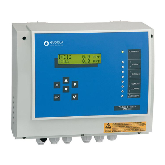
Operation plus 6. Operation Display and operating elements Gas monitoring system GMS plus A Cover B Green LED (power) C Alarm message sensor I D Alarm message sensor II E Common alarms F Sensor error G Operator controls (keys) H LCD display... - Page 70 Operation plus Key functions Operating panel • Move up one level. • Display the previous option. • Increase value. Down • Move down one level. • Display the next option. • Decrease value. Star • Clear latched alarms, clear internal signal transmitter (beeper). unction •...
-
Page 71: Notes On Operation
Operation plus Notes on operation During operation observe the following points: • Check your entries and changes before you leave the menu. • Use only your fingers to press the keys. Do not press keys with hard or pointed objects, otherwise you may damage the sealed keypad (e. - Page 72 Operation plus Removing access code To unblock the gas monitoring system GMS plus from access code entry, Proceed as follows: 1 In the SETUP menu under "Code def." enter the number "000" and save. Please note Changes may be made without entering an access code. The access code query is not displayed in the main menu.
- Page 73 Operation plus Menu navigation • From the basic display, you can access the other menus with the F key. • Use the keys to access the individual sub-menus. • Press the key once or twice to return to the main menu. Press it once more to return to the basic display.
- Page 74 Operation plus • Select the sub-menu you wish to edit. • Press the key and an arrow appears in front of the value to be set. • Use the keys to increase or decrease the value or to skip to the next option. •...
- Page 75 Operation plus 6.2.1 Menu structure The GMS plus has 11 menus: • Main menu • Alarm sensor I • Alarm sensor II • Temperature • Common alarm • Sensor alarm • Calibration • Sensor I • Sensor II • Setup •...
- Page 76 Operation plus General overview WT.050.455.000.DE.IM.0319...
- Page 77 Operation plus Value range Display Description (factory setting, bold) Main menu (display example Cl I: Cl2 2.3ppm Display example: Current gas concentration value of the II: Cl2 1.6ppm Chlorine gas concentration of Sensor sensor channel I and II (chlorine, chlorine I = 2.3 ppm dioxide, ozone or passive mA sensor) Chlorine gas concentration of Sensor...
- Page 78 Operation plus Value range Display Description (factory setting, bold) ALARM SENSOR I Includes all settings for alarms 1 and 2 for sensor channel I Alarmvalue 1 Measuring range start – End value Alarm value for alarm 1 of sensor 1 2.5ppm Alarmdelay 1 l 0.0 –...
- Page 79 Operation plus Value range Display Description (factory setting, bold) ALARM SENSOR II Includes all settings for alarms 1 and 2 for sensor channel II Alarmvalue 1 lI Measuring range start – End value Alarm value for alarm 1 of sensor II 2.5ppm Alarmdelay 1 lI 0.0 –...
- Page 80 Operation plus Value range Display Description (factory setting, bold) TEMPERATURE Includes the temperature alarm settings for temperature sensor I and II Alarmvalue Min l 0 – 50 (°C) Min. alarm value for temperature sensor I 15 °C Alarmvalue Max I 0 –...
- Page 81 Operation plus Value range Display Description (factory setting, bold) COMMONALARM Commonalarm 1 [ ] Al1 Sensor I Assignment of common alarm 1 [ ] Al2 Sensor I [ ] Al1 Sensor II [ ] Al2 Sensor II [ ] Sensoralarm [ ] Temp I min [ ] Temp I max [ ] Temp II min...
- Page 82 Operation plus Value range Display Description (factory setting, bold) Commonalarm 3 [ ] Power Fail * Assignment of common alarm 3 [ ] Common Error [ ] Battery Err* [ ] Batt empty* [ ] Temp I min [ ] Temp I max [ ] Temp II min [ ] Temp II max Multiple assignment possible...
- Page 83 Operation plus Value range Display Description (factory setting, bold) SENSORALARM Sensoral.assign [ ] Sensor I Assignment of sensors to the sensor alarm [ ] Sensor II [ ] Temperature I [ ] Temperature II Multiple assignment possible No assignment Sensoral.delay 0.0 –...
- Page 84 Operation plus Value range Display Description (factory setting, bold) CALIBRATION Sensor calibration and test Test Sensor I Activating the sensor signal test TEST Span Sensor I 0 – 1/5/20 ppm Span calibration of sensor I (Chloratect No selection sensors only) Test Sensor II Activating the sensor signal test TEST...
- Page 85 Operation plus Value range Display Description (factory setting, bold) SENSOR I Setting the parameters for the sensor to be connected to sensor channel I Sensor input I Chloratect Selection of sensors to be connected mA signal OFF (all menus for sensor channel I are hidden and the associated measured values are not displayed.) Senso type I...
- Page 86 Operation plus Value range Display Description (factory setting, bold) SENSOR II Setting the parameters for the sensor to be connected to sensor channel II Sensor input II Chloratect Selection of sensors to be connected mA signal OFF (all menus for sensor channel I are hidden and the associated measured values are not displayed.) Sensortype II...
- Page 87 Operation plus Value range Display Description (factory setting, bold) SETUP General GMS plus settings. Language German, English, French, Dutch, Language setting Spanish Time 00:00 – 24:00 Setting the time Date current date Setting the date 12.12.05 Battery supply OFF/ON Enabling the digital inputs for the battery supply (24 V units only) Beeper [ ] Common alarm...
- Page 88 Operation plus Value range Display Description (factory setting, bold) DIAGNOSIS Error diagnostics Input I for mA sensors in mA The current sensor signal is displayed for measuring range start => 4mA for measuring range end => 20mA for Chloratect sensors in µA for sensor error <...
- Page 89 Operation plus Value range Display Description (factory setting, bold) DI: 1 2 3 4 5 DI1 - door contact sensor I Current signal conditions at digital inputs 1 – DI2 - door contact sensor II 5 are displayed DI3 - external acknowledgement DI4 - see table DI5 - see table Battery empty...
-
Page 90: Errors And Remedies
Operation plus Errors and remedies Error messages The following table shows and explains all possible error messages which can be displayed. If several errors occur at the same time, the corresponding messages appear alternately in succession. When the error has been remedied, the error message is automatically deleted. - Page 91 Operation plus Display Color Meaning Measures ALARM 1 I constant Sensor I, preliminary Follow alarm plan. Remove cause alarm, of alarm. alarm relay triggered Clear alarm ( key or external key at input ext. flashing Sensor I, preliminary acknowledgement for latched fast alarm, door open, alarms).
- Page 92 Operation plus Display Color Meaning Measures COMMON 1 flashing or Common alarm 1 Follow alarm plan. For "latched" COMMON 2 constant active common relay 1 mode: After removing the cause, COMMON 3 triggered clear with the key or external acknowledge key. Remove Common alarm 2 cause of alarm.
- Page 93 Operation plus Display error message Display Meaning Measures "Sensor I ?" Sensor I signal too Check electrolyte low or too high supply Check cable "Sensor II?" Sensor I signal too connection to the low or too high sensor. Check sensor signal in the Diagnosis menu.
- Page 94 Operation plus WT.050.455.000.DE.IM.0319...
-
Page 95: Maintenance
The sensors and the GMS plus must be routinely inspected. Maintenance should be carried out every six months by trained operating personnel or under maintenance contract with Evoqua Water Technologies GmbH. Maintenance will include inspection of the sensor's function, the electrolyte level in the measuring cell and electrical operational safety. -
Page 96: Electrolyte Supply For Chloratect Sensors
Maintenance plus Electrolyte supply for Chloratect sensors Depending on the ambient conditions, one filling of the electrolyte reservoir lasts for (at continuous operation): • Approx. 6 months for Cl and ClO • 3 months for O The entire electrolyte solution must be replaced: •... -
Page 97: Replacing A Fuse Or Battery
Maintenance plus Replacing a fuse or battery Warning! Risk involving electric current. Disconnect the power supply before opening the housing. Only trained electricians are permitted to open the housing. 7.3.1 Replacing the fuse The device fuse must be inspected if: •... - Page 98 1. To this purpose public or private waste disposal companies should be employed. 2. If such an organisation is not available or the products are not accepted, the product can be returned to Evoqua Water Technologies GmbH after prior consultation. WT.050.455.000.DE.IM.0319...
-
Page 99: Recommended Spare Parts
Maintenance plus Recommended spare parts Warning! For reasons of safety, only use original spare parts. Please contact our customer service department if you need any spare parts. Part No. Description W3T173163 Electrolyte Chlorine (Cl W3T173163 Electrolyte Chlorine dioxide (ClO W3T169304 Electrolyte Ozone (O W3T158780 GMS plus electronic PCB... - Page 100 Maintenance plus Part No. Description W3T172553 RS232 Printer type OKI ML1120 W3T164578 Spare ribbon for type Tally T2024/9 W3T172554 Spare ribbon for type OKI ML1120 W3T166182 RS232 Printer cable 3 m W3T166183 RS232Printer cable 15 m W3T172625 CR2032 battery W2T504551 Sensor cable extension (2pol.
-
Page 101: Accessories And Spare Parts
Accessories and spare parts plus 8. Accessories and spare parts Gas monitoring system GMS plus Part No. Description W3T158771 Gas monitoring system GMS plus 230 V W3T158772 Gas monitoring system GMS plus 115 V W3T158773 Gas monitoring system GMS plus 24 V W3T158770 GMS plus battery supply... -
Page 102: Ma Sensors And Sensor Kits
Accessories and spare parts plus mA sensors and sensor kits mA sensors Sensor range Part No. Symbol W3T292492 Sulfur dioxide 0 – 10 W3T292478 Chlorine 0 – 10 W3T292499 Chlorine 0 – 20 Sensor kits Part No. Description W3T302953 Sensor kit GMS plus 0 –... -
Page 103: Wiring Diagrams
Wiring diagrams plus 9. Wiring diagrams... - Page 104 Wiring diagrams plus WT.050.455.000.DE.IM.0319...
- Page 105 Wiring diagrams plus...
- Page 106 Wiring diagrams plus WT.050.455.000.DE.IM.0319...
- Page 107 Wiring diagrams plus...
- Page 108 Wiring diagrams plus WT.050.455.000.DE.IM.0319...
-
Page 109: Declaration Of Conformity
Declaration of conformity plus 10.Declaration of conformity... - Page 110 Declaration of conformity plus WT.050.455.000.DE.IM.0319...
-
Page 111: Index
Index plus 11.Index Chloratect sensor Access code 71 Connecting 50 Defining 71 Refilling 96 Forget 72 Chloratect sensors No INIT display 72 Commissioning 48 Removing 72 Electrolyte supply 96 Adjusting the zero point Error diagnostics 92 Chlorine dioxide sensor 53 Setting input 48 Chlorine sensor 51 Chloratekt sensors... - Page 112 Index plus Electrolyte supply 96 Asterisk 70 Error diagnostics Down 70 Chloratect sensors 92 ENTER 70 Error messages 90 ESCAPE 70 Errors 90 Function 70 Operating panel 70 Up 70 False alarm 50 Filling electrolyte 48 Function test mA outputs 34 Chlorine dioxide sensor 54 Power failure 34 mA sensor 58...
- Page 113 Index plus Design 19 Installation 43 Function 33 Set mains voltage 65 Technical Data 13 Setting the span Chlorine dioxide sensor 53 Chlorine sensor 51 Ozone sensor 55 Replacing the battery 97 Setting the zero point current 49 Replacing the fuse 97 Settings overview 60 Resetting default values 72 Shutdown 66...
- Page 114 Index plus WT.050.455.000.DE.IM.0319...
- Page 115 ® Wallace & Tiernan Products worldwide Australia Canada China +61 3 8720 6597 +1 905 944 2800 +86 10 57076305 info.au@evoqua.com canadainfo@evoqua.com sales.cn@evoqua.com France Germany Singapore +33 1 41 15 92 20 +49 8221 9040 +65 6830 7165 wtfra@evoqua.com wtger@evoqua.com...
- Page 116 Evoqua assumes no responsibility for the completeness of this information. Users are responsible for making sure that the product is suitable for specific applications. Evoqua assumes no liability for specific or indirect damage or consequential damage arising from the sale, resale or misuse of its products.
Need help?
Do you have a question about the WALLACE & TIERNAN GMS PLUS and is the answer not in the manual?
Questions and answers