
Related Manuals for Miller Millermatic 252


Summary of Contents for Miller Millermatic 252
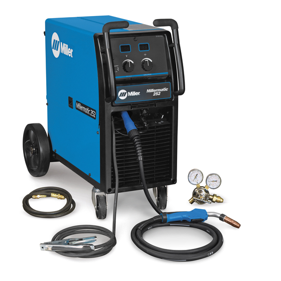
- Page 1 OM-230 693B 2007−07 Processes MIG (GMAW) Welding Flux Cored (FCAW) Welding Description Arc Welding Power Source and Wire Feeder Millermatic 252 Visit our website at File: MIG (GMAW) www.MillerWelds.com...
- Page 2 We know you don’t have time to do it any other way. That’s why when Niels Miller first started building arc welders in 1929, he made sure his products offered long-lasting value and superior quality.
-
Page 3: Table Of Contents
TABLE OF CONTENTS SECTION 1 − SAFETY PRECAUTIONS - READ BEFORE USING ........1-1. - Page 4 TABLE OF CONTENTS SECTION 8 − MIG WELDING (GMAW) GUIDELINES ..........8-1.
-
Page 5: Section 1 − Safety Precautions - Read Before Using
SECTION 1 − SAFETY PRECAUTIONS - READ BEFORE USING som _3/05 Y Warning: Protect yourself and others from injury — read and follow these precautions. 1-1. Symbol Usage Means Warning! Watch Out! There are possible hazards with this procedure! The possible hazards are shown in the adjoining symbols. - Page 6 ARC RAYS can burn eyes and skin. BUILDUP OF GAS can injure or kill. D Shut off shielding gas supply when not in use. Arc rays from the welding process produce intense D Always ventilate confined spaces or use visible and invisible (ultraviolet and infrared) rays that can burn eyes and skin.
-
Page 7: Additional Symbols For Installation, Operation, And Maintenance
D Read Owner’s Manual before using or servic- support unit. ing unit. D If using lift forks to move unit, be sure forks are D Use only genuine Miller/Hobart replacement long enough to extend beyond opposite side of parts. unit. -
Page 8: Principal Safety Standards
1-5. Principal Safety Standards Safety in Welding, Cutting, and Allied Processes, ANSI Standard Z49.1, Boulevard, Rexdale, Ontario, Canada (phone: from Global Engineering Documents (phone: 1-877-413-5184, website: 800−463−6727 or in Toronto 416−747−4044, website: www.csa−in- www.global.ihs.com). ternational.org). Practice For Occupational And Educational Eye And Face Protection, Recommended Safe Practices for the Preparation for Welding and Cut- ANSI Standard Z87.1, from American National Standards Institute, 11 ting of Containers and Piping, American Welding Society Standard... -
Page 9: Section 2 − Consignes De Sécurité − Lire Avant Utilisation
SECTION 2 − CONSIGNES DE SÉCURITÉ − LIRE AVANT UTILISATION fre_som _3/05 Y Avertissement : se protéger et protéger les autres contre le risque de blessure — lire et respecter ces consignes. 2-1. Symboles utilisés Symbole graphique d’avertissement ! Attention ! Cette pro- cédure comporte des risques possibles ! Les dangers éven- tuels sont représentés par les symboles graphiques joints. - Page 10 LES RAYONS D’ARC peuvent entraî- ACCUMULATIONS ner des brûlures aux yeux et à la peau. risquent de provoquer des blessures ou même la mort. Le rayonnement de l’arc du procédé de soudage génère des rayons visibles et invisibles intenses D Fermer l’alimentation du gaz protecteur en cas (ultraviolets et infrarouges) susceptibles de provo- de non-utilisation.
-
Page 11: Dangers Supplémentaires En Relation Avec L'installation, Le Fonctionnement Et La Maintenance
D Utiliser un équipement de levage de capacité D Utiliser uniquement des pièces de rechange suffisante pour lever l’appareil. Miller/Hobart. D En utilisant des fourches de levage pour déplacer l’unité, s’assu- rer que les fourches sont suffisamment longues pour dépasser du côté... -
Page 12: Principales Normes De Sécurité
2-5. Principales normes de sécurité Safety in Welding, Cutting, and Allied Processes, ANSI Standard Z49.1, Boulevard, Rexdale, Ontario, Canada M9W 1R3 (téléphone : de Global Engineering Documents (téléphone : 1-877-413-5184, site In- 800-463-6727 ou à Toronto 416-747-4044, site Internet ternet : www.global.ihs.com). www.csa-international.org). -
Page 13: Section 3 − Definitions
A complete Parts List is available at www.MillerWelds.com SECTION 3 − DEFINITIONS 3-1. Symbols And Definitions Do Not Switch Wire Feed Output Duty Cycle While Welding Volts Increase Gas Metal Arc Wire Feed Spool Welding (GMAW) Gas Input Gas Output Rated No-Load Voltage Input Press To Reset... -
Page 14: Welding Power Source Duty Cycle And Overheating
A complete Parts List is available at www.MillerWelds.com 4-2. Welding Power Source Duty Cycle And Overheating Duty Cycle is percentage of 10 minutes that unit can weld at rated load without overheating. If unit overheats, Thermistor (T) opens, output stops, and cooling fan runs. -
Page 15: Connecting To Weld Output Terminals
A complete Parts List is available at www.MillerWelds.com 4-4. Connecting To Weld Output Terminals Do not place anything between weld cable terminal and copper bar. Tools Needed: 3/4 in (19 mm) 803 778-A Correct Installation Incorrect Installation Y Turn off power before connecting to Weld Output Terminal minal. -
Page 16: Connecting Spoolmatic) 15A Or 30A Gun
A complete Parts List is available at www.MillerWelds.com 4-6. Connecting Spoolmatic) 15A Or 30A Gun Gun Trigger Plug Insert plug into receptacle, and tighten threaded collar. Weld Cable Shielding Gas Hose Route weld cable through opening in front panel. Route gas hose along side panel. Positive Weld Output Terminal Connect weld cable to weld output terminal. -
Page 17: Connecting Xr Aluma-Pro, Xr Edge, Xr-A Gun, Or Xr-A Python
A complete Parts List is available at www.MillerWelds.com 4-7. Connecting XR Aluma-Pro, XR Edge, XR-A Gun, Or XR-A Python XR Edge guns prior to serial no. LE079101 require an adapter cord (part no. 195 498). Gun End Gun Liner Wire Outlet Guide Trim excess liner from end of gun so no more than 3/32 in (2.4 mm) of liner extends past wire outlet guide. -
Page 18: Setting Gun Polarity For Wire Type
A complete Parts List is available at www.MillerWelds.com 4-8. Setting Gun Polarity For Wire Type Polarity Changeover Label Changing Polarity Information Always read and follow manufacture’s recommended polarity. Wire Drive Work Clamp Lead Assembly Lead Positive Terminal Negative Terminal Shown as shipped − Electrode Positive (DCEP): For solid steel, stainless steel, aluminum, or flux core with gas wires (GMAW). -
Page 19: Installing Wire Spool And Adjusting Hub Tension
A complete Parts List is available at www.MillerWelds.com 4-10. Installing Wire Spool And Adjusting Hub Tension Use compression spring When a slight force is needed with 8 in (200 mm) spools. to turn spool, tension is set. To install either a 1 lb or 2 lb wire Installing 1 Or 2 lb Wire Spool spool, follow the procedure as Spindle... -
Page 20: Electrical Service Guide
A complete Parts List is available at www.MillerWelds.com 4-12. Electrical Service Guide Input Voltage Input Amperes At Rated Output Max Recommended Standard Fuse Or Circuit Breaker Rating In Amperes Circuit Breaker , Time-Delay Normal Operating Min Input Conductor Size In AWG Max Recommended Input Conductor Length In Feet (Meters) (29) (39) -
Page 21: Selecting A Location And Connecting Input Power
A complete Parts List is available at www.MillerWelds.com 4-13. Selecting A Location And Connecting Input Power =GND/PE Earth Ground 18 in (457 mm) of space for airflow Y Do not move or operate unit where it could tip. 230 VAC, 1 804 912-A Y Installation must meet all National Plug (NEMA Type 6-50P) -
Page 22: Threading Welding Wire
A complete Parts List is available at www.MillerWelds.com 4-14. Threading Welding Wire Wire Spool Welding Wire Inlet Wire Guide Pressure Adjustment Knob Drive Roll Outlet Wire Guide Gun Conduit Cable Lay gun cable out straight. Tools Needed: Hold wire tightly to keep it from unraveling. - Page 23 A complete Parts List is available at www.MillerWelds.com Notes OM-230 693 Page 19...
-
Page 24: Weld Parameters
A complete Parts List is available at www.MillerWelds.com 4-15. Weld Parameters OM-230 693 Page 20... - Page 25 A complete Parts List is available at www.MillerWelds.com 226 650-B OM-230 693 Page 21...
-
Page 26: Section 5 − Operation
A complete Parts List is available at www.MillerWelds.com SECTION 5 − OPERATION 5-1. Controls Voltage Control Turn control clockwise to increase voltage. Wire Speed Control Turn control clockwise to increase wire feed speed. Voltmeter Wire Feed Speed Meter This unit has three automatic timers included in its operation to help save contact tips, gas, and wire: Tip Saver −... - Page 27 A complete Parts List is available at www.MillerWelds.com JOG Mode which is recommended for most wire sizes trigger and pull trigger again and types. momentarily (one second). If the trigger on either gun is held for more than 3 seconds without striking an arc, the To change Run−in settings, start with the Spool Gun Run−in is factory set at 50% unit will automatically shut off weld power...
-
Page 28: Voltmeter And Wire Feed Speed Meter Operation
A complete Parts List is available at www.MillerWelds.com 5-2. Voltmeter And Wire Feed Speed Meter Operation Voltmeter Welding Status Gun Selection When either a MIG gun or spool gun trigger Wire Feed Speed Meter The wire feed speed meter will display is pressed and a welding arc is established, preset wire feed speed (IPM) for the the voltmeter displays actual weld voltage. -
Page 29: Timers
A complete Parts List is available at www.MillerWelds.com 5-4. Timers Voltage Control Run-in speed (run) − The speed of the wire gized after the wire feeding has stopped. prior to the welding arc being struck. The The range is from 0.01 to 0.25 seconds. Wire Speed Control range is from 25 to 150% of wire feed Spot Timer (SPO) −... -
Page 30: Set Up Push Motor Torque (Sup) Or Reset (Res)
A complete Parts List is available at www.MillerWelds.com Welding wire birdnesting at the welding power source drive rolls may occur if this value is set too high. 5-5. Set Up Push Motor Torque (SUP) Or Reset (rES) Voltage Control The following items can be adjusted by over-torque limit and speed up the remote rotating the left knob counterclockwise wire feed speed motor. -
Page 31: Section 6 − Maintenance &Troubleshooting
A complete Parts List is available at www.MillerWelds.com SECTION 6 − MAINTENANCE &TROUBLESHOOTING 6-1. Routine Maintenance Y Disconnect power Maintain more often before maintaining. during severe conditions. n = Check Z = Change ~ = Clean l = Replace Reference * To be done by Factory Authorized Service Agent Every Months... -
Page 32: Aligning Drive Rolls And Wire Guide
A complete Parts List is available at www.MillerWelds.com 6-4. Aligning Drive Rolls and Wire Guide Y Turn Off power. View is from top of drive rolls looking down with pressure assembly open. Drive Roll Securing Nut Correct Incorrect Drive Roll Wire Guide Welding Wire Drive Gear... -
Page 33: Troubleshooting
A complete Parts List is available at www.MillerWelds.com 6-5. Troubleshooting Trouble Remedy Be sure line disconnect switch is On (see Section 4-13). No weld output; wire does not feed. Replace building line fuse or reset circuit breaker if open (see Section 4-13). Secure gun trigger connections (see welding gun Owner’s Manual). - Page 34 A complete Parts List is available at www.MillerWelds.com Trouble Remedy No wire feed. Turn Wire Speed control to higher setting (see Section 5-1). Clear obstruction in gun contact tip or liner (see welding gun Owner’s Manual). Readjust drive roll pressure (see Section 4-14). Change to correct size drive rolls (see Section 6-3).
- Page 35 Notes OM-230 693 Page 31...
-
Page 36: Section 7 − Electrical Diagram
SECTION 7 − ELECTRICAL DIAGRAM Figure 7-1. Circuit Diagram OM-230 693 Page 32... - Page 37 229 485-A OM-230 693 Page 33...
-
Page 38: Section 8 − Mig Welding (Gmaw) Guidelines
SECTION 8 − MIG WELDING (GMAW) GUIDELINES 8-1. Typical MIG Process Connections Y Weld current can damage electronic parts in vehicles. Disconnect both battery cables before welding on a vehicle. Place work clamp as close to the weld as possible. Regulator/ Flowmeter Wire Feeder/... -
Page 39: Typical Mig Process Control Settings
8-2. Typical MIG Process Control Settings These settings are guidelines only. Material and wire type, joint design, fitup, position, shielding gas, etc. affect settings. Test welds to be sure they comply to specifications. Material thickness determines weld parameters. 1/8 or Convert Material .125 in Thickness to... -
Page 40: Holding And Positioning Welding Gun
8-3. Holding And Positioning Welding Gun Welding wire is energized when gun trigger is pressed. Before lowering helmet and pressing trigger, be sure wire is no more than 1/2 in (13 mm) past end of nozzle, and tip of wire is positioned correctly on seam. Hold Gun and Control Gun Trigger Workpiece... -
Page 41: Conditions That Affect Weld Bead Shape
8-4. Conditions That Affect Weld Bead Shape Weld bead shape depends on gun angle, direction of travel, electrode extension (stickout), travel speed, thickness of base metal, wire feed speed (weld current), and voltage. ° Push ° Perpendicular Drag GUN ANGLES AND WELD BEAD PROFILES Short Normal Long... -
Page 42: Gun Movement During Welding
8-5. Gun Movement During Welding Normally, a single stringer bead is satisfactory for most narrow groove weld joints; however, for wide groove weld joints or bridging across gaps, a weave bead or multiple stringer beads works better. Stringer Bead − Steady Movement Along Seam Weave Bead −... -
Page 43: Troubleshooting − Excessive Spatter
8-8. Troubleshooting − Excessive Spatter Excessive Spatter − scattering of molten metal particles that cool to solid form near weld bead. S-0636 Possible Causes Corrective Actions Wire feed speed too high. Select lower wire feed speed. Voltage too high. Select lower voltage range. Electrode extension (stickout) too long. -
Page 44: Troubleshooting − Lack Of Penetration
8-11. Troubleshooting − Lack Of Penetration Lack Of Penetration − shallow fusion between weld metal and base metal. Lack of Penetration Good Penetration S-0638 Possible Causes Corrective Actions Improper joint preparation. Material too thick. Joint preparation and design must provide access to bottom of groove while maintaining proper welding wire extension and arc characteristics. -
Page 45: Troubleshooting − Waviness Of Bead
8-14. Troubleshooting − Waviness Of Bead Waviness Of Bead − weld metal that is not parallel and does not cover joint formed by base metal. S-0641 Possible Causes Corrective Actions Welding wire extends too far out of nozzle. Be sure welding wire extends not more than 1/2 in (13 mm) beyond nozzle. Unsteady hand. -
Page 46: Common Mig Shielding Gases
8-16. Common MIG Shielding Gases This is a general chart for common gases and where they are used. Many different combinations (mixtures) of shielding gases have been developed over the years. The most commonly used shielding gases are listed in the following table. - Page 47 Problem Probable Cause Remedy Welding arc not stable. Wire slipping in drive rolls. Adjust pressure setting on wire feed rolls. Replace worn drive rolls if necessary. Wrong size gun liner or contact tip. Match liner and contact tip to wire size and type. Incorrect voltage setting for selected wire feed speed on Readjust welding parameters.
-
Page 48: Section 9 − Parts List
SECTION 9 − PARTS LIST 9-1. Drive Roll And Wire Guide Kits Note Base selection of drive rolls upon the following recommended usages: V-Grooved rolls for hard wire. U-Grooved rolls for soft and soft shelled cored wires. U-Cogged rolls for extremely soft shelled wires (usually hard surfacing types). V-Knurled rolls for hard shelled cored wires. - Page 49 Notes...
- Page 50 Notes...
- Page 51 Effective January 1, 2007 (Equipment with a serial number preface of “LH” or newer) This limited warranty supersedes all previous Miller warranties and is exclusive with no other Warranty Questions? guarantees or warranties expressed or implied. LIMITED WARRANTY − Subject to the terms and conditions...
- Page 52 Contact the Delivering Carrier to: File a claim for loss or damage during shipment. For assistance in filing or settling claims, contact your distributor and/or equipment manufacturer’s Transportation Department. © PRINTED IN USA 2007 Miller Electric Mfg. Co. 2007−01...
Need help?
Do you have a question about the Millermatic 252 and is the answer not in the manual?
Questions and answers