Table of Contents
Advertisement
Advertisement
Table of Contents
Troubleshooting

Related Manuals for Miller Big Blue 251D


Summary of Contents for Miller Big Blue 251D
- Page 1 OM-480 128 576AA October 2002 Processes Stick (SMAW) Welding Air Carbon Arc (CAC-A) Cutting And Gouging With Optional Equipment: Flux Cored (FCAW) With Voltage-Sensing Wire Feeder Description Engine Driven Welding Generator Big Blue 251D Visit our website at www.MillerWelds.com...
- Page 2 We know you don’t have time to do it any other way. That’s why when Niels Miller first started building arc welders in 1929, he made sure his products offered long-lasting value and superior quality.
-
Page 3: Table Of Contents
TABLE OF CONTENTS SECTION 1 – SAFETY PRECAUTIONS - READ BEFORE USING ......1-1. Symbol Usage . -
Page 5: Section 1 - Safety Precautions - Read Before Using
SECTION 1 – SAFETY PRECAUTIONS – READ BEFORE USING rom _nd_10/02 Y Warning: Protect yourself and others from injury — read and follow these precautions. 1-1. Symbol Usage Means Warning! Watch Out! There are possible hazards with this procedure! The possible hazards are shown in the adjoining symbols. -
Page 6: Engine Hazards
BUILDUP OF GAS can injure or kill. FLYING METAL can injure eyes. D Shut off shielding gas supply when not in use. D Welding, chipping, wire brushing, and grinding D Always ventilate confined spaces or use cause sparks and flying metal. As welds cool, they can throw off slag. -
Page 7: Additional Symbols For Installation, Operation, And Maintenance
MOVING PARTS can cause injury. ENGINE EXHAUST GASES can kill. D Keep away from fans, belts, and rotors. D Use equipment outside in open, well-ventilated D Keep all doors, panels, covers, and guards areas. D If used in a closed area, vent engine exhaust closed and securely in place. -
Page 8: Principal Safety Standards
READ INSTRUCTIONS. D Locate welding operation 100 meters from any sensitive elec- tronic equipment. D Use only genuine MILLER/Hobart replacement D Be sure this welding machine is installed and grounded parts. according to this manual. -
Page 9: Section 1 - Consignes De Sécurité - Lire Avant Utilisation
SECTION 1 – CONSIGNES DE SÉCURITÉ – LIRE AVANT UTILISATION rom _nd_fre 4/02 1-1. Signification des symboles Signifie Mise en garde ! Soyez vigilant ! Cette procédure présente des risques de danger ! Ceux-ci sont identifiés par des symboles adjacents aux directives. Ce groupe de symboles signifie Mise en garde ! Soyez vigilant ! Il y a des Y Identifie un message de sécurité... -
Page 10: Dangers Existant En Relation Avec Le Moteur
LE SOUDAGE peut provoquer un in- DES PIÈCES CHAUDES peuvent cendie ou une explosion. provoquer des brûlures graves. D Prévoir une période de refroidissement avant d’effec- Le soudage effectué sur des conteneurs fermés tels que tuer des travaux d’entretien. des réservoirs, tambours ou des conduites peut provoquer D Porter des gants et des vêtements de protection pour leur éclatement. -
Page 11: Dangers Supplémentaires En Relation Avec L'installation, Le Fonctionnement Et La Maintenance
DES ORGANES MOBILES peuvent L’ACIDE DE LA BATTERIE peut pro- provoquer des blessures. voquer des brûlures dans les YEUX et sur la PEAU. D Ne pas approcher les mains des ventilateurs, cour- roies et autres pièces en mouvement. D Ne pas renverser la batterie. D Maintenir fermés et fixement en place les portes, D Remplacer une batterie endommagée. -
Page 12: Principales Normes De Sécurité
LE RAYONNEMENT HAUTE FRÉ- LE SOUDAGE À L’ARC risque de QUENCE (H.F.) risque de provoquer provoquer des interférences. des interférences. D L’énergie électromagnétique risque de provoquer des interférences pour l’équipement électronique D Le rayonnement haute fréquence (H.F.) peut sensible tel que les ordinateurs et l’équipement com- provoquer des interférences avec les équipements mandé... -
Page 13: Section 2 - Definitions
SECTION 2 – DEFINITIONS 2-1. Symbols And Definitions Fast (Run, Weld/ Stop Engine Slow (Idle) Start Engine Power) Fast/Slow Battery (Engine) Circuit Breaker Engine Oil (Run/Idle) Check Injectors/ Check Valve Protective Earth Fuel Pump Clearance (Ground) Certified/Trained Positive Negative Welding Arc Mechanic Amperes Volts... -
Page 14: Section 3 - Specifications
SECTION 3 – SPECIFICATIONS 3-1. Weld, Power, And Engine Specifications Maximum Open-Circuit Rated Welding Amperage Voltage DC Generator Power Engine Fuel Capacity Output Range Rating (Nominal) Deutz F3L-1011 250 A, Single-Phase, Air/Oil-Cooled, 40 Volts DC, 40 – 400 95 (90) 3 kVA/kW, 26 A, 11.3 gal (42.8 L) Three-Cylinder,... -
Page 15: Fuel Consumption
3-3. Fuel Consumption The curve shows typical fuel use under weld or power loads. SB-137 487-A 3-4. Duty Cycle And Overheating Duty Cycle is percentage of 10 min- utes that unit can weld at rated load 100% Duty Cycle At 250 Amperes without overheating. -
Page 16: Volt-Ampere Curves
3-5. AC Generator Power The ac power curve shows the gen- erator power in amperes available at the 120 and 240 volt receptacles. AC AMPERES IN 240V MODE AC AMPERES IN 120V MODE rsb3.1 2/92 – 206 031 3-6. Volt-Ampere Curves The volt-ampere curve shows the minimum and maximum voltage and amperage output capabilities of... -
Page 17: Optional Ac Power Plant Curves
3-7. Optional AC Power Plant Curves The ac power curves show the gen- erator power in amperes available at the single-phase 120/240 volt or three-phase 240 volt terminals. A. 7.5 KVA/KW Single-Phase AC Power Plant (No Weld Load) B. 10 KVA/KW Three-Phase AC Power Plant (No Weld Load) AC AMPERES rsb13.1 12/94 - 134 636-A / 206 032 OM-480 Page 13... -
Page 18: Section 4 - Installation
SECTION 4 – INSTALLATION 4-1. Installing Welding Generator Movement Airflow Clearance Location 18 in Y Do Not Lift Unit From End (460 mm) 18 in (460 mm) 18 in (460 mm) 18 in 18 in (460 mm) (460 mm) Y Always securely fasten welding Grounding generator onto transport vehicle or trailer and comply with all DOT... -
Page 19: Installing Muffler Pipe
4-3. Installing Muffler Pipe Y Stop engine and let cool. Y Do not blow exhaust toward air cleaner or air intake. Top View Tools Needed: 1/2 in exh_pipe2 12/96 – 154 089-A / 154 611 / Ref. 206 029 4-4. Engine Prestart Checks Check all fluids daily. -
Page 20: Installing Ether Cylinder (Optional Ether Starting Aid)
4-5. Installing Ether Cylinder (Optional Ether Starting Aid) Y Stop engine. Y Improper handling or expo- sure to ether can harm your health. Follow manufactur- er’s safety instructions on cylinder. Y Do not use Ether Starting Aid while engine is running. Open side door(s). -
Page 21: Selecting Weld Cable Sizes
4-7. Selecting Weld Cable Sizes* Weld Cable Size** and Total Cable (Copper) Length in Weld Circuit Not Exceeding*** 150 ft 200 ft 250 ft 300 ft 350 ft 400 ft 100 ft (30 m) or Less (45 m) (60 m) (70 m) (90 m) (105 m) -
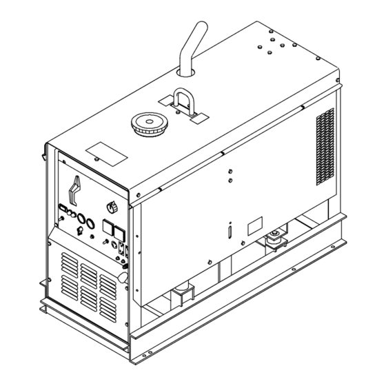
Page 22: Section 5 - Operating The Welding Generator
SECTION 5 – OPERATING THE WELDING GENERATOR 5-1. Controls (See Section 5-2) Ref. 206 029 / 800 162-A / 800 159-D OM-480 Page 18... -
Page 23: Description Of Front Panel Controls (See Section 5-1)
5-2. Description Of Front Panel Controls (See Section 5-1) (See Section 5-3) Light goes on if oil pressure is too low. If unit This unit has a max OCV control circuit has automatic shutdown option, light also Magnetic Shutdown Switch (Optional) that resets the Amperage/Voltage Con- goes on if oil temperature is too high. -
Page 24: Section 6 - Operating Auxiliary Equipment
SECTION 6 – OPERATING AUXILIARY EQUIPMENT 6-1. 120 Volt Duplex And Optional GFCI Receptacles Y If unit does not have GFCI re- ceptacles, use GFCI-pro- tected extension cord. 120 V 15 A AC Receptacle 120 V 15 A AC Receptacle 120 V 20 A AC GFCI Receptacles GFCI1 And GFCI2 (Optional) -
Page 25: Volt Duplex Receptacle (Optional)
6-2. 240 Volt Duplex Receptacle (Optional) Y If unit does not have GFCI re- ceptacles, use GFCI-pro- tected extension cord. 240 V 15 A AC Receptacle Receptacle supplies 60 Hz single- phase power at weld/power speed. Maximum output is 3 kVA/kW. Circuit Breakers CB1 And protect receptacles from overload. -
Page 26: Connecting Optional Ac Power Plant
6-3. Connecting Optional AC Power Plant Y Stop engine. Y Power and weld outputs are live same time. Disconnect insulate unused cables. Have qualified person install according to circuit diagram and Generator Power Guide- lines (Section 10). Remove junction box cover. Lead 93 Lead 92 Lead 91... -
Page 27: 120/240 Volt Twistlock Receptacle (Optional)
6-4. 120/240 Volt Twistlock Receptacle (Optional) 120/240 V 50 A Twistlock Re- ceptacle RC9 RC9 is connected to the optional ac power plant and supplies 60 Hz single-phase power at weld/power speed. Maximum output from re- ceptacle is 7.5 kVA/kW. Power available at RC9 is reduced when welding. -
Page 28: Section 7 - Maintenance And Troubleshooting
SECTION 7 – MAINTENANCE AND TROUBLESHOOTING 7-1. Routine Maintenance Y Stop engine before maintaining. See also Engine Manual and Maintenance Label. Recycle engine Service engine more often if used in severe condi- tions. fluids. To be done by Factory Authorized Service Agent. Drain Water FUEL Check Fluid... -
Page 29: Maintenance Label
Follow the storage procedure in the engine owner’s manual if the unit will not be NOTE used for an extended period. 7-2. Maintenance Label OM-480 Page 25... -
Page 30: Servicing Air Cleaner
7-3. Servicing Air Cleaner Y Stop engine. Y Do not run engine without air cleaner or with dirty element. En- gine damage caused by using a damaged element is not covered by the warranty. The air cleaner primary element can be cleaned but the dirt holding ca- pacity of the filter is reduced with each cleaning. -
Page 31: Servicing Fuel And Lubrication Systems
7-4. Servicing Fuel And Lubrication Systems Y Stop engine and let cool. Oil Filter Oil Drain Plug Oil Fill Cap Primary Fuel Filter (Fuel/ Water Separator) Petcock Secondary Fuel Filter Fuel Shutoff Valve Fuel Line Sludge Drain Plug To change oil and filter: See engine manual. -
Page 32: Adjusting Engine Speed
7-5. Adjusting Engine Speed After tuning engine, check engine no load speed with a tachometer (see table for no load speeds). If necessary, adjust speed as follows: Start engine and run until warm. Turn Amperage/Voltage Control to 100. Standard Models: Engine Speed Adjustment Screw Locking Nut... -
Page 33: Overload Protection
7-6. Overload Protection Y Stop engine. When a fuse opens, it usually indicates a more serious prob- lem exists. Contact a Factory Authorized Service Agent. Magnetic Shutdown Switch MS1 (Optional) Fuse F (See Parts List) Fuse F protects magnetic shut- down switch MS1. -
Page 34: Inspecting And Cleaning Optional Spark Arrestor
7-8. Inspecting And Cleaning Optional Spark Arrestor Y Stop engine and let cool. Spark Arrestor Cleanout Plug Remove plug and remove any dirt covering cleanout hole. Exhaust Pipe Start engine and run at idle speed to blow out cleanout hole. If nothing blows out of hole, briefly cover end of exhaust pipe with fireproof material. - Page 35 B. Generator Power Trouble Remedy output generator power Reset circuit breaker CB1 and/or CB2 (see Section 6-1 or 6-2). receptacles. Disconnect equipment from generator power receptacles during start-up. Have Factory Authorized Service Agent check brushes and slip rings, and field excitation circuit. Low or high output at generator power Check engine speed, and adjust if necessary (see Section 7-5).
-
Page 36: Section 8 - Electrical Diagram
SECTION 8 – ELECTRICAL DIAGRAM SC-190 650-B Figure 8-1. Circuit Diagram For Welding Generator OM-480 Page 32... -
Page 37: Section 9 - Run-In Procedure
SECTION 9 – RUN-IN PROCEDURE run_in1 8/01 9-1. Wetstacking Y Do perform run-in procedure at less than 20 volts weld output and do not exceed duty cycle or equip- ment damage may occur. Welding Generator Run diesel engines near rated volt- age and current during run-in period to properly seat piston rings and prevent wetstacking. -
Page 38: Run-In Procedure Using Load Bank
9-2. Run-In Procedure Using Load Bank Y Stop engine. Y Do not touch hot exhaust pipe, engine parts, or load bank/grid. Y Keep exhaust and pipe away from flammables. Y Do perform run-in procedure at less than 20 volts weld output and do not exceed duty cycle or equip- ment damage may occur. -
Page 39: Run-In Procedure Using Resistance Grid
9-3. Run-In Procedure Using Resistance Grid Y Stop engine. Y Do not touch hot exhaust pipe, engine parts, or load bank/grid. Y Keep exhaust and pipe away from flammables. Y Do perform run-in procedure at less than 20 volts weld output and do not exceed duty cycle or equip- ment damage may occur. -
Page 40: Grounding Generator To Truck Or Trailer Frame
SECTION 10 – GENERATOR POWER GUIDELINES 10-1. Selecting Equipment Generator Power Receptacles – Neutral Bonded To Frame 3-Prong Plug From Case Grounded Equipment 2-Prong Plug From Double Insulated Equipment Y Do not use 2-prong plug un- less equipment is double in- sulated. -
Page 41: Grounding When Supplying Building Systems
10-3. Grounding When Supplying Building Systems Equipment Grounding Terminal Grounding Cable GND/PE Use #10 AWG or larger insulated copper wire. Ground Device Y Ground generator to system earth ground if supplying power to a premises (home, shop, farm) wiring system. Use ground device as stated in electrical codes. - Page 42 10-5. Approximate Power Requirements For Industrial Motors Industrial Motors Rating Starting Watts Running Watts Split Phase 1/8 HP 1/6 HP 1225 1/4 HP 1600 1/3 HP 2100 1/2 HP 3175 Capacitor Start-Induction Run 1/3 HP 2020 1/2 HP 3075 3/4 HP 4500 1400 1 HP...
- Page 43 10-7. Approximate Power Requirements For Contractor Equipment Contractor Rating Starting Watts Running Watts Hand Drill 1/4 in 3/8 in 1/2 in Circular Saw 6-1/2 in 7-1/4 in 8-1/4 in 1400 1400 Table Saw 9 in 4500 1500 10 in 6300 1800 Band Saw 14 in...
- Page 44 10-8. Power Required To Start Motor Motor Start Code AC MOTOR Running Amperage VOLTS AMPS Motor HP CODE Motor Voltage PHASE To find starting amperage: Step 1: Find code and use table to find kVA/HP. If code is not listed, multiply running amperage by six to find starting amperage.
- Page 45 10-10. Typical Connections To Supply Standby Power Y Properly install and ground this equipment according to its Owner’s Manual and national, state, and local codes. Fused Utility Welding Disconnect Electrical Generator Transfer Switch Switch Service Output (If Required) Essential Loads Y Have only qualified persons perform Switch transfers the electrical load from Connect generator with temporary or perma-...
- Page 46 10-11. Selecting Extension Cord (Use Shortest Cord Possible) Cord Lengths for 120 Volt Loads Y If unit does not have GFCI receptacles, use GFCI-protected extension cord. Maximum Allowable Cord Length in ft (m) for Conductor Size (AWG)* Current Load (Watts) (Amperes) 350 (106) 225 (68)
- Page 47 Notes OM-480 Page 43...
-
Page 48: Section 11 - Parts List
SECTION 11 – PARTS LIST Hardware is common and not available unless listed. 71(Includes 72–77) 111(Fig 11-2) Figure 11-1. Main Assembly OM-480 Page 44... - Page 49 65(Fig 11–3) ST-129 956-T OM-480 Page 45...
- Page 50 Item Dia. Part Mkgs. Description Quantity Figure 11-1. Main Assembly ....134 771 PLUG, protective .640sq .........
- Page 51 Item Dia. Part Mkgs. Description Quantity Figure 11-1. Main Assembly ..... 128 287 STUD, adjusting throttle ........♦127 648 .
- Page 52 Item Dia. Part Mkgs. Description Quantity Figure 11-1. Main Assembly ....173 982 PANEL, mtg components ........
- Page 53 Item Dia. Part Mkgs. Description Quantity Figure 11-2. Panel, Front w/Components (Fig 11-1 Item 111) (Cont’d) ....021 385 BOOT, toggle switch lever .
- Page 54 Hardware is common and not available unless listed. Figure 11-3. Generator ST-110 922-F OM-480 Page 50...
- Page 55 Item Dia. Part Mkgs. Description Quantity Figure 11-3. Generator (Fig 11-1 Item 65) ....106 426 INSULATOR ............
- Page 56 Item Part Description Quantity 114 193 Figure 11-4. Switch, Range (Fig 11-2 Item 1) ....114 235 BRACKET, mtg switch (consisting of) ........
- Page 59 Effective January 1, 2002 (Equipment with a serial number preface of “LC” or newer) This limited warranty supersedes all previous Miller warranties and is exclusive with no other Warranty Questions? guarantees or warranties expressed or implied. Call LIMITED WARRANTY – Subject to the terms and conditions APT, ZIPCUT &...
-
Page 60: Options And Accessories
Distributor Address City State For Service Call 1-800-4-A-Miller or see our website at www.MillerWelds.com to locate a DISTRIBUTOR or SERVICE AGENCY near you. Always provide Model Name and Serial/Style Number. Contact your Distributor for: Welding Supplies and Consumables Options and Accessories...
Need help?
Do you have a question about the Big Blue 251D and is the answer not in the manual?
Questions and answers