
Related Manuals for Vega SOLITRAC 31


Summary of Contents for Vega SOLITRAC 31
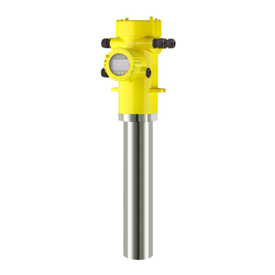
- Page 1 Operating Instructions Radiometric sensor for continuous level and interface measurement SOLITRAC 31 Profibus PA Document ID: 43834...
-
Page 2: Table Of Contents
Parameter adjustment with PACTware ................61 Saving the parameterisation data ................... 62 Set up with other systems ....................63 DD adjustment programs ....................63 Diagnostics and servicing ....................64 Maintenance ........................64 Status messages ......................64 Rectify faults ........................67 SOLITRAC 31 • Profibus PA... - Page 3 Safety instructions for Ex areas Take note of the Ex specific safety instructions for Ex applications. These instructions are attached as documents to each instrument with Ex approval and are part of the operating instructions. Editing status: 2021-11-25 SOLITRAC 31 • Profibus PA...
-
Page 4: About This Document
Symbols used Document ID This symbol on the front page of this instruction refers to the Docu- ment ID. By entering the Document ID on www.vega.com you will reach the document download. Information, note, tip: This symbol indicates helpful additional infor- mation and tips for successful work. -
Page 5: For Your Safety
During work on and with the device, the required personal protective equipment must always be worn. Appropriate use SOLITRAC 31 is a sensor for continuous level measurement. You can find detailed information about the area of application in chapter " Product description". -
Page 6: Eu Conformity
The environment management system is certified according to DIN EN ISO 14001. Please help us fulfil this obligation by observing the environmental instructions in this manual: • Chapter " Packaging, transport and storage" • Chapter " Disposal" SOLITRAC 31 • Profibus PA... -
Page 7: Product Description
Alternatively, you can access the data via your smartphone: • Download the VEGA Tools app from the " Apple App Store" or the " Google Play Store" • Scan the QR-code on the type label of the device or •... -
Page 8: Principle Of Operation
Ascertained transit damage or con- cealed defects must be appropriately dealt with. Storage Up to the time of installation, the packages must be left closed and stored according to the orientation and storage markings on the outside. SOLITRAC 31 • Profibus PA... -
Page 9: Accessories
VEGACONNECT The interface adapter VEGACONNECT enables the connection of communication-capable instruments to the USB interface of a PC. VEGADIS 81 The VEGADIS 81 is an external display and adjustment unit for VEGA plics sensors. ® Electronics module - The electronics module PT30…... - Page 10 For ambient temperatures up to 120 °C (248 °C) the gamma modula- tor is optionally available with water cooling. Any number of devices can be synchronized. To synchronize several gamma modulators, you need a controller. SOLITRAC 31 • Profibus PA...
-
Page 11: Corresponding Source Container
Time: Stay as short a time as possible in radiation exposed areas. Distance: Your distance to the source should be as large as possible. The local dose rate of the radiation decreases in proportion to the square of the distance to the radiation source. SOLITRAC 31 • Profibus PA... - Page 12 (in Ger- many, for example, the radiation protection ordinance). We are at your disposal for further information concerning radiation protection and regulations in other countries. SOLITRAC 31 • Profibus PA...
-
Page 13: Mounting
These are mainly: • Active measuring component • Process fitting • Process seal Process conditions in particular are: • Process pressure • Process temperature • Chemical properties of the medium • Abrasion and mechanical influences SOLITRAC 31 • Profibus PA... -
Page 14: Mounting Instructions
You must follow the instructions in this "Source Sizing" document in addition to the following mounting instructions. The following mounting information is applicable as long as there is nothing else specified in the "Source Sizing" document. Fig. 4: Level measurement in a storage tank SOLITRAC 31 • Profibus PA... - Page 15 VEGASOURCE. You can mount the SOLITRAC 31 with the housing head upward or downward. When the housing head is mounted downward, the hous- ing itself is more easily accessible.
- Page 16 Make sure that the red marking lines directly join the measuring range of the next SOLITRAC 31. Mount the SOLITRAC 31 in such a way that the detector tube is directly in the radiated area of the source container. Mount the SOLITRAC 31 preferably side by side and make sure that no detector tube is hidden by another sensor.
- Page 17 If these measures are not sufficient to maintain the max. ambient temperature, you could consider using the water or air cooling system we offer for SOLITRAC 31. The cooling system must also be included in the calculations for the measuring point. Contact our specialists regarding the dimensioning of the cooling.
-
Page 18: Connecting To Power Supply
In the case of instrument housings with metric thread, the cable glands are screwed in at the factory. They are sealed with plastic plugs as transport protection. You have to remove these plugs before electrical connection. SOLITRAC 31 • Profibus PA... - Page 19 3. Remove approx. 10 cm (4 in) of the cable mantle, strip approx. 1 cm (0.4 in) of insulation from the ends of the individual wires 4. Insert the cable into the sensor through the cable entry SOLITRAC 31 • Profibus PA...
- Page 20 To do this, loosen the two lateral locking levers of the terminal block with a small screwdriver. When loosening the locking, the terminal block is automatically squeezed out. It must snap in place when re-inserted. SOLITRAC 31 • Profibus PA...
-
Page 21: Connection - Level Measurement
Contact pins for the display and adjustment module or interface adapter Instruments with intrinsically safe signal output You can find detailed information on the explosion-protected versions (Ex-ia, Ex-d) in the Ex-specific safety instructions. These safety MGC = Multi Gauge Communication SOLITRAC 31 • Profibus PA... - Page 22 Fig. 12: Adjustment and connection compartment (Ex-ia) with instruments with intrinsically safe signal output 1 Terminals - Signal output Profibus PA Contact pins for the display and adjustment module or interface adapter Terminals for the external display and adjustment unit Ground terminal MGC = Multi Gauge Communication SOLITRAC 31 • Profibus PA...
-
Page 23: Connection - Level Detection
Contact pins for the display and adjustment module or interface adapter Connection to a PLC If inductive loads or stronger currents are switched through, the gold plating on the relay contact surface will be permanently damaged. MGC = Multi Gauge Communication SOLITRAC 31 • Profibus PA... - Page 24 Signal input 4 … 20 mA (active sensor) Switching input for NPN transistor 6 Switching input floating Transistor output Interface for sensor-sensor communication (MGC) Setting the bus address for sensor-sensor communication (MGC) MGC = Multi Gauge Communication SOLITRAC 31 • Profibus PA...
-
Page 25: Connection - Summation
Secondary". Select under the menu item " Setup - Application" the function "Summation Secondary". The address setting (MGC) on the Secondary instruments can be freely selected. Only the address "99" is reserved for the Primary instrument. SOLITRAC 31 • Profibus PA... - Page 26 M Primary instrument S Secondary instrument Information: For example, a radial connection would be also possible as an alter- native. Take note of the polarity. The selection of the two terminal pairs is individual. SOLITRAC 31 • Profibus PA...
-
Page 27: Set Instrument Address
Software addressing is only effective if address 126 or higher is set on the instrument with the address selection switches. The addressing procedure is described in the operating instructions manual " Display and adjustment module. SOLITRAC 31 • Profibus PA... -
Page 28: Set Up With The Display And Adjustment Module
Fig. 19: Insert display and adjustment module Note: If you intend to retrofit the instrument with a display and adjustment module for continuous measured value indication, a higher lid with an inspection glass is required. SOLITRAC 31 • Profibus PA... -
Page 29: Adjustment System
" English". Approx. 60 minutes after the last pressing of a key, an automatic reset to measured value indication is triggered. Any values not confirmed with [OK] will not be saved. SOLITRAC 31 • Profibus PA... -
Page 30: Parameter Adjustment - Level Measurement
" Display - Menu language". Start with the setup of SOLITRAC 31. In the main menu item " Setup", the individual submenu items should be selected one after the other and provided with the correct param- eters to ensure optimum setting of the measurement. - Page 31 • Special characters + - / _ blanks Isotope In this menu item you can adjust the SOLITRAC 31 to the isotope installed in the source container. For this purpose, check which isotope is in the source container. You can find this information on the type label of the source container.
- Page 32 The normal reduction of source activity through radioactive decay is thus taken into account. The SOLITRAC 31 requires this information for the automatic decay compensation. This ensures error-free measurement over the entire lifetime of the gamma emitter - an annual recalibration is not neces- sary.
- Page 33 (0 %). Depending on whether the vessel is full or empty, you can first carry out the full or the empty adjustment. The SOLITRAC 31 sorts the points automatically according to their level. Select " Show table" to display and edit the linearisation points.
- Page 34 If you cannot fill the vessel during the adjustment procedure to at least 60 % of the max. level, it is possible to carry out the full adjustment by switching off the radiation. The switched-off radiation simulates a 100 % filling. SOLITRAC 31 • Profibus PA...
- Page 35 Since the adjustment is very comprehensive, the menu points of Function Blocks 1 (FB1) were put together in a submenu. In menu item" Channel" you determine which measured value the Setup - AI FB1 - Channel output refers to. SOLITRAC 31 • Profibus PA...
- Page 36 With the setting "Automatic", the instrument itself calculates a suitable damping on the basis of the adjustment and the measured value changes. This setting is particularly suitable for application where fast and slow level changes occur. SOLITRAC 31 • Profibus PA...
- Page 37 • Process value • External radiation Push the [->] button, to reach the relay settings. Example for the adjustment of the process value. First of all select the requested mode (overfill or dry run protection). SOLITRAC 31 • Profibus PA...
- Page 38 If no language is preset, you will be asked during setup. Displayed value With this parameter you can change the indication of the display. You can choose for example if the display should show the actual pulse rate, the electronics temperature or the percentage value. SOLITRAC 31 • Profibus PA...
- Page 39 (switch position 1). You can find the rotary switch on the electronics module in the elec- tronics and connection department (large cover). You can simulate different values: SOLITRAC 31 • Profibus PA...
- Page 40 When a reset is carried out, all settings (with only a few exceptions) are reset. The exceptions are: PIN, language and SIL. The following reset functions are available: Basic settings: Resetting of the parameter adjustments to default values at the time of shipment. Order-specific settings are deleted. SOLITRAC 31 • Profibus PA...
- Page 41 Reference value - Relay None Lock adjustment Released Display Language Selected language Displayed value Pulse rate (ct/s) Copy instrument settings With this function • Load parameter adjustment data from the sensor into the display and adjustment module SOLITRAC 31 • Profibus PA...
-
Page 42: Parameter Adjustment - Summation Secondary
The pulse rates of all instruments are summed in the Primary instru- ment and converted into a common signal. First of all, define the function of the Secondary instruments before you define the Primary instrument. The Primary instrument can thus immediately recognize the connected Secondaries. SOLITRAC 31 • Profibus PA... - Page 43 " Display - Menu language". Start with the setup of SOLITRAC 31. In the main menu item " Setup", the individual submenu items should be selected one after the other and provided with the correct param- eters to ensure optimum setting of the measurement.
- Page 44 Hardware addressing is effective if an address less than 126 is set with the address selection switches on the electronics module of SOLITRAC 31. In such case, software addressing has no effect - only the set hardware address applies. Software addressing Software addressing is only effective if address 126 or higher is set on the instrument with the address selection switches.
- Page 45 In this menu item you can activate the function of the current output. When the output is activated, the instrument remains in its function as a Secondary, but the 4 … 20 mA output of the SOLITRAC 31 can be also used als single instrument.
- Page 46 With locked instrument, only the following adjustment functions are possible without entering a PIN: • Select menu items and show data • Read data from the sensor into the display and adjustment module SOLITRAC 31 • Profibus PA...
- Page 47 The following table shows the default values of the instrument. The values apply for the application " Summation Secondary". The ap- plication must be selected first. Depending on the instrument version, not all menu items may be available or they may be differently assigned: SOLITRAC 31 • Profibus PA...
-
Page 48: Parameter Adjustment - Point Level Detection
Info: Instrument name, hardware and software version, date of manu- facture, instrument features Procedure Check if the correct language is already set for the display. If not, you can change the language in the menu item " Display - Menu language". SOLITRAC 31 • Profibus PA... - Page 49 Hardware addressing is effective if an address less than 126 is set with the address selection switches on the electronics module of SOLITRAC 31. In such case, software addressing has no effect - only the set hardware address applies. Software addressing Software addressing is only effective if address 126 or higher is set on the instrument with the address selection switches.
- Page 50 • Special characters + - / _ blanks Isotope In this menu item you can adjust the SOLITRAC 31 to the isotope installed in the source container. For this purpose, check which isotope is in the source container. You can find this information on the type label of the source container.
- Page 51 This menu item appears only if you have selected " Single point (single point adjustment) adjustment" as adjustment mode (Setup - Adjustment mode). In this menu item you determine the point at which the SOLITRAC 31 should switch in uncovered status. Empty the vessel until the sensor is uncovered.
- Page 52 Enter the requested pulse rate manually or let the rate be determined by SOLITRAC 31. Automatic determination of the pulse rate should be given preference. You can enter the adjustment point (ct/s) manually. You can let the adjustment point be determined by SOLITRAC 31. SOLITRAC 31 • Profibus PA...
- Page 53 SOLITRAC 31. Automatic determination of the pulse rate should be given preference. You can enter the adjustment point (ct/s) manually. You can let the adjustment point be determined by SOLITRAC 31. AI FB1 Since the adjustment is very comprehensive, the menu points of Function Blocks 1 (FB1) were put together in a submenu.
- Page 54 In the menu item " Lock/unlock adjustment", you can protect the sen- sor parameters against unauthorized or inadvertent modification. The sensor is locked/unlocked permanently. With locked instrument, only the following adjustment functions are possible without entering a PIN: SOLITRAC 31 • Profibus PA...
- Page 55 Device status In this menu item, you can enquire the status of your sensor. In normal operation, the sensor displays the message " OK". In case of fault, you will find the corresponding fault code here. SOLITRAC 31 • Profibus PA...
- Page 56 (switch position 1). You can find the rotary switch on the electronics module in the elec- tronics and connection department (large cover). You can simulate different values: Pulse rate of the sensor SOLITRAC 31 • Profibus PA...
- Page 57 Peak values of measured value: Resetting of the parameter adjust- ments in the menu item " Setup" to the default values of the respec- tive instrument. Order-specific settings remain but are not taken over into the current parameters. SOLITRAC 31 • Profibus PA...
- Page 58 In Multidrop mode, several sensors are communicating on one two- wire cable via the HART protocol. In Multidrop mode, up to 15 sensors can be operated on one two-wire cable. An address between 1 and 15 must be assigned to each sen- sor. SOLITRAC 31 • Profibus PA...
-
Page 59: Saving The Parameterisation Data
Examples for info display: Saving the parameterisation data On paper We recommended writing down the adjustment data, e.g. in this op- erating instructions manual, and archiving them afterwards. They are thus available for multiple use or service purposes. SOLITRAC 31 • Profibus PA... - Page 60 If the instrument is equipped with a display and adjustment module, In the display and adjust- ment module the parameter adjustment data can be saved therein. The procedure is described in menu item " Copy device settings". SOLITRAC 31 • Profibus PA...
-
Page 61: Setup With Pactware
Further setup steps are described in the operating instructions manu- al " DTM Collection/PACTware" attached to each DTM Collection and which can also be downloaded from the Internet. Detailed descrip- tions are available in the online help of PACTware and the DTMs. SOLITRAC 31 • Profibus PA... -
Page 62: Saving The Parameterisation Data
The standard version is available as a download under www.vega.com/downloads and " Software". The full version is avail- able on CD from the agency serving you. Saving the parameterisation data We recommend documenting or saving the parameterisation data via PACTware. -
Page 63: Set Up With Other Systems
Set up with other systems DD adjustment programs Device descriptions as Enhanced Device Description (EDD) are available for DD adjustment programs such as, for example, AMS™ and PDM. The files can be downloaded at www.vega.com/downloads under " Software". SOLITRAC 31 • Profibus PA... -
Page 64: Diagnostics And Servicing
Maintenance required: Due to external influences, the instrument function is limited. The measurement is affected, but the measured value is still valid. Plan in maintenance for the instrument because a failure is expected in the near future (e.g. due to buildup). SOLITRAC 31 • Profibus PA... - Page 65 Cool the instrument or protect it with iso- lation material against heat/cold F041 Error in the measured value recording Restart instrument Photomultiplier error Exchanging the electronics F052 Invalid parameter adjustment Carry out a reset Faulty configuration SOLITRAC 31 • Profibus PA...
- Page 66 Error in the trend recording F141 Secondary instrument does not answer Check Secondary instruments Communication error on the multisensor communica- tion bus Tab. 4: Error codes and text messages, information on causes as well as corrective measures SOLITRAC 31 • Profibus PA...
-
Page 67: Rectify Faults
PACTware and suitable DTM. In many case, the failure reasons can thus be determined and faults rectified. The following table describes possible errors with the output signal Check output signal (level measurement) and helps to remove them: SOLITRAC 31 • Profibus PA... -
Page 68: Exchanging The Electronics Module
Should these measures not be successful, please call in urgent cases 24 hour service hotline the VEGA service hotline under the phone no. +49 1805 858550. The hotline is also available outside normal working hours, seven days a week around the clock. -
Page 69: Software Update
By doing this you help us carry out the repair quickly and without hav- ing to call back for needed information. If a repair is necessary, please proceed as follows: SOLITRAC 31 • Profibus PA... - Page 70 Attach the completed form and, if need be, also a safety data sheet outside on the packaging • Please contact the agency serving you to get the address for the return shipment. You can find the agency on our home page www.vega.com. SOLITRAC 31 • Profibus PA...
-
Page 71: Dismount
Pass the instrument directly on to a specialised recycling company and do not use the municipal collecting points. If you have no way to dispose of the old instrument properly, please contact us concerning return and disposal. SOLITRAC 31 • Profibus PA... -
Page 72: Supplement
Max. torque, mounting screws Ʋ Fastening lugs in the sensor housing 15 Nm (11.1 lbf ft), stainless steel A4-70 Max. torque for NPT cable glands and Conduit tubes Ʋ Aluminium/Stainless steel housing 50 Nm (36.88 lbf ft) SOLITRAC 31 • Profibus PA... - Page 73 The measured variable is the intensity of the gamma radiation of an isotope. When the radiation intensity decreases, for example due to rising medium, the measured value of SOLITRAC 31 changes in proportion to the level. Fig. 24: Data of the input variable Min.
- Page 74 The contact is then no longer suitable for switching low-level signal circuits. Contact material (relay contacts) AgNi or AgSnO2 each with 3 µm gold plating SOLITRAC 31 • Profibus PA...
- Page 75 Time span after a sudden measuring distance change by max. 0.5 m in liquid applications, max 2 m with bulk solids applications, until the output signal has taken for the first time 90 % of the final value (IEC 61298-2). Tested according to the guidelines of German Lloyd, GL directive 2. SOLITRAC 31 • Profibus PA...
- Page 76 Number of sensors per DP/PA segment coupler, max. Electrical protective measures Application area Outdoor areas Altitude above sea level 2000 m (6561 ft) Protection class Pollution degree Relative humidity max. 100 % Micro-environment in housing: pollution degree 2 SOLITRAC 31 • Profibus PA...
-
Page 77: Device Communication Profibus Pa
The below block diagram below shows which data can be accessed by the PLC. A suitable cable is required for maintaining the protection rating. Alternative: Overvoltage category II with operating height up to 5000 m SOLITRAC 31 • Profibus PA... - Page 78 Primary Temperature Rate Value Fig. 25: SOLITRAC 31: Block diagram with AI FB 1 … AI FB 3 OUT values TB Transducer Block FB 1 … FB 3 Function Block Output value, adjustable (depending on instrument type and application - see following list) •...
- Page 79 The status byte corresponds to profile 3.02 "Profibus PA Profile for Process Control Devices" coded. The status "Measured value OK" is coded as 80 (hex) (Bit7 = 1, Bit6 … 0 = 0). The measured value is transferred as a 32 bit floating point number in the IEEE-754 format. SOLITRAC 31 • Profibus PA...
- Page 80 16, 17, 25, 52, 53, 57, 66, FAILURE 117, 120 Conflict in MGC 121, 122, 141 FAILURE Communication Error in MGC FAILURE MGC-Secondary reports Error FAILURE Undefined 21 Undefined 20 Undefined 19 Detector Temperature critical OUT_OF_SPEC Error while Auto-Standardization FAILURE SOLITRAC 31 • Profibus PA...
-
Page 81: Dimensions
You can adapt the settings according to PA profile 3.02. See DIAG_EVENT_SWITCH. 11.3 Dimensions The following dimensional drawings represent only an extract of all possible versions. Detailed dimensional drawings can be downloaded at www.vega.com/downloads under " Drawings". SOLITRAC 31 • Profibus PA... - Page 82 Aluminium and stainless steel housing M20x1,5/ 119 mm ½ NPT (4.69") 169 mm (6.65") 116,5 mm 175 mm (4.59") (6.89") 90 mm 100 mm (3.54") (3.94") 143,5 mm (5.65") Fig. 28: Aluminium housing or stainless steel housing (precision casting) SOLITRAC 31 • Profibus PA...
- Page 83 11 Supplement SOLITRAC 31 ø 76,2 mm (3") Fig. 29: SOLITRAC 31 Measuring range (order length of instruments) SOLITRAC 31 • Profibus PA...
- Page 84 70 mm (2.76") 195 mm (7.68") 152,5 mm (6.00") 127 mm (5.00") 51 mm (2.01") 14 mm 14,3 mm (0.55") (0.56") Fig. 30: SOLITRAC 31 with supplied mounting accessories L1 Distance of the mounting clamps SOLITRAC 31 • Profibus PA...
-
Page 85: Industrial Property Rights
Les lignes de produits VEGA sont globalement protégées par des droits de propriété intellec- tuelle. Pour plus d'informations, on pourra se référer au site www.vega.com. VEGA lineas de productos están protegidas por los derechos en el campo de la propiedad indus- trial. Para mayor información revise la pagina web www.vega.com. - Page 86 PACTware 61 PA modules 78 Peak value indicator 39, 56 EDD (Enhanced Device Description) 63 Protection class 18 Fault rectification 67 Radiation protection 11 Functional principle 8 Radiation safety officer 12 Real value correction 37 SOLITRAC 31 • Profibus PA...
- Page 87 Source 31, 45, 50 Source holder 11 Status bytes PA output value 80 Summation Secondary 42 Telegram configuration 79 Time 40, 57 Type label 7 Unit 51 Units 32 Voltage supply 18 Water cooling 17 SOLITRAC 31 • Profibus PA...
- Page 88 Subject to change without prior notice © VEGA Grieshaber KG, Schiltach/Germany 2021 VEGA Grieshaber KG Am Hohenstein 113 Phone +49 7836 50-0 77761 Schiltach E-mail: info.de@vega.com...
Need help?
Do you have a question about the SOLITRAC 31 and is the answer not in the manual?
Questions and answers