Table of Contents
Advertisement
Quick Links
Advertisement
Table of Contents

Related Manuals for Ublox EVK-JODY-W2


Summary of Contents for Ublox EVK-JODY-W2
- Page 1 EVK-JODY-W2 Evaluation kit for JODY-W2 host-based modules User guide Abstract This document describes how to set up the EVK-JODY-W2 evaluation kit to evaluate JODY-W2 series multiradio modules with Wi-Fi and Bluetooth. UBX-19027118 - R04 C1 - Public www.u-blox.com...
-
Page 2: Document Information
EVK-JODY-W2 - User guide Document information Title EVK-JODY-W2 Subtitle Evaluation kit for JODY-W2 host-based modules Document type User guide Document number UBX-19027118 Revision and date 19-Feb-2021 Disclosure restriction C1 - Public This document applies to the following products: Production status... -
Page 3: Table Of Contents
EVK-JODY-W2 - User guide Contents Document information ..........................2 Contents ............................... 3 Kit description ............................4 1.1 Overview ................................ 4 1.2 Kit includes ..............................5 1.3 Software ................................ 6 1.4 System requirements ..........................6 Specifications ............................7 2.1 Operating conditions ..........................7 2.2 SDIO operating voltage .......................... -
Page 4: Kit Description
Bluetooth, and Bluetooth Low Energy (LE) communication, and are ideal for automotive and industrial applications. EVK-JODY-W2 allows an external host processor to access several practical features for testing and evaluating the Wi-Fi and Bluetooth connectivity supported in JODY-W2 series modules, including: •... -
Page 5: Kit Includes
EVK-JODY-W2 - User guide 1.2 Kit includes Connectors for the use of different interfaces of the module are included in the evaluation kit. Table 2 shows the various components included in the EVK-JODY-W2. Part Description Outline Evaluation board (EVB) Evaluation board for JODY-W263 series modules. -
Page 6: Software
EVK-JODY-W2 - User guide 1.3 Software The reference driver developed by NXP is only distributed to customers that have signed a Limited Use License Agreement (LULA-M) with u-blox. Contact your local u-blox support office for information about how to obtain the driver package. -
Page 7: Specifications
EVK-JODY-W2 - User guide Specifications This section describes the different operating parameters for the EVK-JODY-W2. 2.1 Operating conditions Table 3 describes the absolute range for key EVK operating parameters. Symbol Parameter Min. Typ. Max. Units VBAT Power supply voltage I/O supply voltage 1.8 V 1.67... -
Page 8: Getting Started
EVK-JODY-W2 - User guide Getting started Different jumpers and connectors are needed to set-up the EVK-JODY-W2. The various configurations and setup procedures are explained in this chapter. J104, J105, J106: J300, J302, Power supply J303: Control SW500, SW501: J205: USB type C... -
Page 9: Jumpers And Connectors
EVK-JODY-W2 - User guide 3.1 Jumpers and connectors Table 4 provides a summary of the connectors and jumpers used to configure EVK-JODY-W2. Designator Connector Description J104, J105, Power supply configuration Jumper settings for power supply configuration (4.3) J106 J1 - J7 Input voltage configuration Jumper settings for selecting the input voltage for the module from power supply configuration (4.4) -
Page 10: Host Interface For Wi-Fi (3.3 V Hs)
3.4 Host interface for Wi-Fi (3.3 V HS) By default, EVK-JODY-W2 operates with host interface voltage of 1.8 V. For the designs with host interface voltage 3.3 V, a level shifter is needed to convert the voltage level of all the signals. Using 3.3 V the SDIO interface operates in High Speed (HS) mode. -
Page 11: Host Interface For Bluetooth
EVK-JODY-W2 - User guide These resistors must be connected in vertical positions. Figure 5: Resistor modification to enable host connection through an adapter 3.5 Host interface for Bluetooth JODY-W2 series modules support a high-speed UART interface for Bluetooth communication. A USB-to-UART bridge (FTDI FT231X) is included on the evaluation board. Follow the procedure outlined below to connect the board to a host system through USB. -
Page 12: Board Description
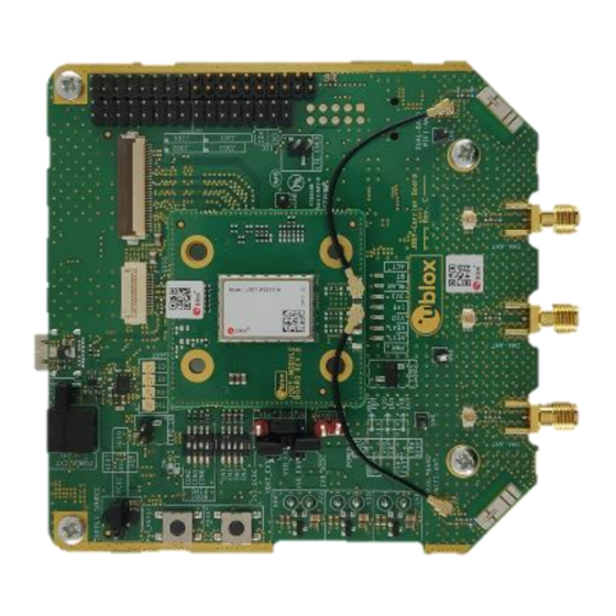
EVK-JODY-W2. 4.1 Block diagram EVK-JODY-W2 design is organized between the module board and carrier board. The carrier board includes all the necessary peripherals and connectors. It also includes a slot for mounting the module board. Module board holds the JODY-W2 module. Figure 6 shows the placement of carrier boards in relation to the module boards of the EVK-JODY-W2. -
Page 13: Jumper Conventions
USB: If Bluetooth is connected through USB, the bus can also be used as a power supply. • External power supply: EVK-JODY-W2 can be powered by an external 5 V to 24 V supply using a terminal connector or power jack. In this case, a DC-DC converter is used for generating all the required internal voltages. - Page 14 EVK-JODY-W2 - User guide Figure 9 describes pins used to enable power supply to the module. Jumper to enable power via SDIO LEDs for different interface voltage level verification Pins for voltage measurements Single external supply to cater all the input...
- Page 15 EVK-JODY-W2 - User guide Figure 11 describes the different voltage sources and derived limits. Figure 11: Derived voltage limits using different sources The available external voltage sources are shown in Figure 12. Figure 12: Input voltage sources Jumpers J104 and J105 determine the power supply for the EVK. Later the required input voltage levels are obtained by passing the source through the DC-DC converter, as shown in Figure 12 .
-
Page 16: Input Voltage Levels
Table 6: Input voltage options For the operation of EVK-JODY-W2, we need to set jumpers as explained in Table 5 and Table 7. The first one selects the input power supply and the later one defines the voltage levels to operate the module. -
Page 17: Sdio Interface
EVK-JODY-W2 - User guide Jumper settings Remarks/Voltage levels Power supply using individual input source for each of the voltage levels Voltage is derived from individual source supplies connected to the EVK. The supplies are connected at the bottom of the EVK carrier boards. -
Page 18: Bluetooth Uart Interface
EVK-JODY-W2 - User guide VDD_SDIO is connected to the power supply connector (J105) and is used for supplying 3.3 V for VBAT from the SDIO interface. The SDIO interface has 50 Ω impedance. The SDIO signals are powered by the 1V8 voltage domain. -
Page 19: Control Lines
EVK-JODY-W2 - User guide Place jumpers J401 and J402 on the bottom side of the EVK to enable the audio codec. Figure 16: Enable audio codec option The I2C interface of the audio codec is provided on connector J303 of the EVK as shown in Figure 17 and Table 9. -
Page 20: General Settings
EVK-JODY-W2 - User guide Figure 18 shows the switches that need to be set to define the boot up mode and subsequent physical interface that is used for Bluetooth communication. Figure 18: Circuit for DIP switches 4.9.1 General settings Jumper J400 and DIP switch SW503 must be configured to use Bluetooth over any interface. -
Page 21: Bluetooth Over Uart
EVK-JODY-W2 - User guide Switching the DIP switch ON will connect the signal (CON0) to ground (GND). Set DIP switch in SW503 to the appropriate position to select the boot configuration for the Bluetooth interface, as shown in Table 10. -
Page 22: Leds
ANT1 ANT0 ANT1 ANT0 Figure 20: Connection of pig-tail coaxial cables with the U.FL adapters 4.11 LEDs Table 12 describes the function and description of the available LEDs on the EVK-JODY-W2 evaluation board. Function Description Designator Color Main power supply (VBAT) status indication... -
Page 23: Appendix
EVK-JODY-W2 - User guide Appendix A Glossary Abbreviation Definition Evaluation board Evaluation kit Host controller interface Input / output Inter-Integrated circuit sound Light-Emitting Diode Low-dropout regulator Low-power oscillator Long-Term Evolution Medium access control MIMO Multiple input multiple output Multimedia card... -
Page 24: Related Documents
EVK-JODY-W2 - User guide Related documents JODY-W2 series data sheet, UBX-18017567 JODY-W2 system integration manual, UBX-18068879 JODY-W2 level shifter integration application note, UBX-19034257 EVK-JODY-W2 schematics. Connector for the power jack, terminal connector power jack ☞ For product change notifications and regular updates of u-blox documentation, register on our website, www.u-blox.com. -
Page 25: Revision History
4-Dec-2020 aheg Added full-sized SDIO adapter in Table 2: EVK-JODY-W2 component list; revised Wi- Fi host interface in sections 3.3 and 3.4; revised Figure 6 and Figure 20 to show carrier and module and pig-tail coaxial cable connections with U.FL adapters; removed obsolete WLAN/BT LED notifications in Table 12;... -
Page 26: Contact
EVK-JODY-W2 - User guide Contact For complete contact information, visit us at www.u-blox.com. u-blox Offices North, Central and South America Headquarters Asia, Australia, Pacific Europe, Middle East, Africa u-blox America, Inc. u-blox Singapore Pte. Ltd. u-blox AG Phone: +1 703 483 3180...
Need help?
Do you have a question about the EVK-JODY-W2 and is the answer not in the manual?
Questions and answers