Table of Contents
Advertisement
Quick Links
Advertisement
Table of Contents

Related Manuals for Ublox EVK-MAYA-W1


Summary of Contents for Ublox EVK-MAYA-W1
- Page 1 EVK-MAYA-W1 Evaluation kit for MAYA-W1 host-based modules User guide Abstract This document describes how to set up the EVK-MAYA-W1 evaluation kit to evaluate MAYA-W1 series multiradio modules with Wi-Fi and Bluetooth. UBX-21039658 - R01 C1 – Public www.u-blox.com...
-
Page 2: Document Information
EVK-MAYA-W1 - User guide Document information Title EVK-MAYA-W1 Subtitle Evaluation kit for MAYA-W1 host-based modules Document type User guide Document number UBX-21039658 Revision and date 24-Nov-2021 Disclosure restriction C1 – Public This document applies to the following products: Product name... -
Page 3: Table Of Contents
EVK-MAYA-W1 - User guide Contents Document information ..........................2 Contents ............................... 3 Kit description ............................4 1.1 Overview ................................ 4 1.2 Kit includes ..............................5 1.3 Software ................................ 6 1.3.1 Driver source code ..........................6 1.3.2 Calibration data ........................... 6 1.4 System requirements .......................... -
Page 4: Kit Description
Android. Wi-Fi/Bluetooth support for RTOS is provided by the NXP MCUXpresso SDK on NXP i.MX RT MCUs. EVK-MAYA-W1 allows an external host processor to access several practical features for testing and evaluating the Wi-Fi and Bluetooth connectivity supported in MAYA-W1 series modules, including: •... -
Page 5: Kit Includes
EVK-MAYA-W1 - User guide 1.2 Kit includes Table 2 shows the various components included in the EVK-MAYA-W1. Part Description Outline Evaluation board (EVB) Evaluation board for the MAYA-W1 series modules. EVK-MAYA-W161 includes SMA antenna connectors that connect to external antennas for Wi-Fi and Bluetooth. -
Page 6: Software
Wi-Fi and Bluetooth features, see also the NXP User Manual UM11490 [4] Contact your local u-blox support team for information about additional software options for the MAYA-W1 series modules. 1.3.2 Calibration data To ensure that EVK-MAYA-W1 prototypes operate correctly, calibration data must be loaded from separate configuration files. Calibration data... -
Page 7: System Requirements
Supported operating systems: Linux (3.x/4.x/5.x) Android FreeRTOS™ (through NXP MCUXpresso) 1.5 Operating conditions Table 3 describes the recommended operating conditions for the EVK-MAYA-W1. For more information about power supply requirements, see also the MAYA-W1 series data sheet [1]. Symbol Parameter Min. -
Page 8: Getting Started
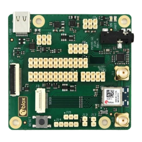
(J3) Figure 2: Evaluation board of EVK-MAYA-W161 overview showing main connectors Follow the procedure below to evaluate MAYA-W1 series module using EVK-MAYA-W1: Connect the external antennas for EVK-MAYA-W161. EVK-MAYA-W161 includes two external dual-band antennas for Wi-Fi and Bluetooth communication, which must be connected to the SMA connectors (J10 and J11) on the evaluation board. - Page 9 EVK-MAYA-W1 - User guide EVK-MAYA-W1 can optionally be connected to a host system through an M.2 Key E host socket. M.2 sockets with mechanical Key E are used on several host platforms, including platforms based on NXP MPUs and MCUs that support wireless connectivity modules based on NXP Wi-Fi/Bluetooth radios.
-
Page 10: Board Description
EVK-MAYA-W1 - User guide Board description 3.1 Block diagram Figure 3 shows a block diagram of the evaluation board with the M.2 and SD card adapters. Figure 3: Block diagram of the EVB and adapter cards UBX-21039658 - R01 Board description... -
Page 11: Jumpers And Connectors
J3: SDIO / M.2 card J10: ANT0 SW1: Reset J14: RF J15: J13: Boot J12: Sleep button control Coex. config. clock enable Figure 4: EVK-MAYA-W1 connectors and default jumper configuration UBX-21039658 - R01 Board description Page 11 of 22... -
Page 12: Power Supply Configuration
EVK-MAYA-W1 - User guide Table 4 provides a summary of the connectors and pin headers available on the evaluation board. Designator Function Description USB connector USB type-C connector for Bluetooth host interface M.2 card connector Connector for M.2 card adapter SDIO/M.2 card connector... -
Page 13: Vio Configuration
EVK-MAYA-W1 - User guide 3.3.2 VIO configuration The VIO and VIO_SD voltages for the MAYA-W1 module can be selected from the 1.8 V or 3.3 V board supplies with pin header J8. The default configuration is to use 1.8 V for both VIO (3-4) and VIO_SD (7-8). -
Page 14: Sdio Card Interface
EVK-MAYA-W1 - User guide 3.5.1 SDIO card interface Micro SD and full-size SD card adapters are included in the EVK to connect the evaluation board to SDIO capable host sockets. To use one of the SDIO card adapters, connect it with the smaller flat cable to the ZIF connector J3 on the EVB. -
Page 15: Bluetooth Host Interface
EVK-MAYA-W1 - User guide Figure 9: M.2 card ZIF connector (J2) and pin headers J4/5 The M.2 Key E pinout follows the definition from NXP for M.2 sockets on platforms based on NXP MPUs and MCUs. For more information about the Wi-Fi/Bluetooth M.2 Key E Pinout Definition on NXP host boards, see also the NXP AN13049 pin definition [6]. -
Page 16: Bluetooth Audio Interface
EVK-MAYA-W1 - User guide The routing and selection of the Bluetooth host interface modes is configured using the jumpers on pin header J6 and J4, as shown in Figure 10 and also Figure 9. Figure 10: USB/UART selection (J6) The configuration options for the Bluetooth host interface modes are described in Table 5. -
Page 17: Gpios
J12. Figure 11 shows the module RF control signals and the WCI-2 coexistence interface accessible on J14 and J15. Figure 11: RF controls (J14) and coexistence (J15) interfaces 3.10 LEDs Table 8 describes the function and designation of the available LEDs on the EVK-MAYA-W1 evaluation board. Function Description... -
Page 18: Reset Button
EVK-MAYA-W1 - User guide 3.11 Reset button Press the SW1 button on the EVB to reset the MAYA-W1 module. When pressed, SW1 asserts the PDn pin of the MAYA-W1 module to enter power down mode, while keeping the supply rails enabled. -
Page 19: Appendix
EVK-MAYA-W1 - User guide Appendix A Glossary Abbreviation Definition Evaluation board Evaluation kit Host controller interface Input / output Inter-Integrated circuit sound Light-Emitting Diode Low-dropout regulator Low-power oscillator Long-Term Evolution Medium access control MIMO Multiple input multiple output Multimedia card... -
Page 20: Related Documents
EVK-MAYA-W1 - User guide Related documents MAYA-W1 series data sheet, UBX-21006380 MAYA-W1 system integration manual, UBX-21010495 Embedded Linux for i.MX Applications Processors NXP UM11490 - Feature Configuration Guide for NXP-based Wireless Modules on i.MX 8M Quad MCUXpresso Software Development Kit (SDK) NXP AN13049 - Wi-Fi/Bluetooth M.2 Key E Pinout Definition... -
Page 21: Revision History
EVK-MAYA-W1 - User guide Revision history Revision Date Name Comments 24-Nov-2021 mzes Initial release. UBX-21039658 - R01 Revision history Page 21 of 22 C1 – Public... -
Page 22: Contact
EVK-MAYA-W1 - User guide Contact For complete contact information, visit us at www.u-blox.com. u-blox Offices North, Central and South America Headquarters Asia, Australia, Pacific Europe, Middle East, Africa u-blox America, Inc. u-blox Singapore Pte. Ltd. u-blox AG Phone: +1 703 483 3180...
Need help?
Do you have a question about the EVK-MAYA-W1 and is the answer not in the manual?
Questions and answers