Table of Contents

Related Manuals for Toa VX-3308WM


Summary of Contents for Toa VX-3308WM
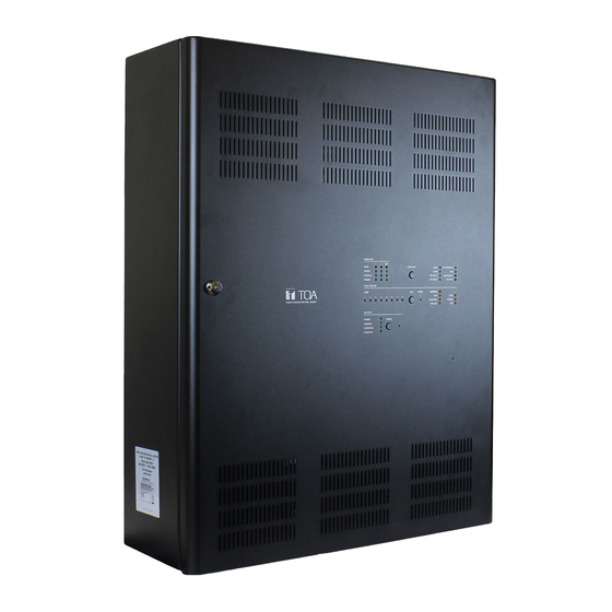
- Page 1 OPERATING INSTRUCTIONS VOICE EVACUATION WALL MOUNT VX-3308WM Thank you for purchasing TOA's Voice Evacuation Wall Mount. Please carefully follow the instructions in this manual to ensure long, trouble-free use of your equipment.
-
Page 2: Table Of Contents
TABLE OF CONTENTS Chapter 1 : NOMENCLATURE 1. VX-3308WM VOICE EVACUATION WALL MOUNT ........... 2. RM-200SF FIREMAN’S MICROPHONE AND RM-320F REMOTE MICROPHONE EXTENSION....2.1. RM-200SF........................1-5 2.2. RM-320F...........................1-7 3. RM-300X REMOTE MICROPHONE AND RM-210F REMOTE MICROPHONE EXTENSION....3.1. RM-300X...........................1-8 3.2. - Page 3 4.2. Making All-zone Emergency Broadcast from the RM-300X........3-18 4.3. Making All-zone Emergency Broadcast from the RM-200SF........ 3-19 5. DETECTING FAULT..............3-20 5.1. Fault Detection Setting....................3-20 5.2. Case Example of Malfunction..................3-21 5.3. Remote Microphone's Operation ................3-22 5.4. VX-3308WM's Operation ....................3-23...
- Page 4 5.5. Example of Executing the Failure Reception and Failure Reset by Way of the Control Input Terminals..............3-24 6. LAMP TEST................... 3-25 6.1. Remote Microphone's Operation Example............... 3-25 6.2. VX-3308WM's Operation ................... 3-26 7. OTHER FUNCTIONS..............3-27 7.1. Audio Monitor......................... 3-27 7.2. Intended Control Input Operation................3-28...
-
Page 5: Chapter 1 : Nomenclature
Chapter 1 NOMENCLATURE... -
Page 6: Vx-3308Wm Voice Evacuation Wall Mount
NOMENCLATURE Chapter 1 VX-3308WM VOICE EVACUATION WALL MOUNT [Front]... - Page 7 NOMENCLATURE Chapter 1 1. Power indicator (Green) 11. Amplifier operate indicators (Green) The indicator corresponding to the module slot Lights when the power is supplied. Flashes in standby state. port will light or go off depending on the operation state of the power amplifier when the 2.
- Page 8 26. Charging indicator [CHARGING] Lights while in a CPU off state (p. 3-17) or when Indicates battery charging status. Flashes green a failure is detected in the VX-3308WM. while charging, and continuously lights green after charging completion. 17. General fault indicator (Yellow) Lights while in a CPU off state (p.
-
Page 9: Rm-200Sf Fireman's Microphone And Rm-320F Remote Microphone Extension
NOMENCLATURE Chapter 1 2. RM-200SF FIREMAN’S MICROPHONE AND RM-320F REMOTE MICROPHONE EXTENSION 2.1. RM-200SF • The RM-200SF Fireman’s Microphone features 3 function keys, 1 emergency key, 1 talk key, and the indicator lamps associated with these keys. Functions are assigned to the function keys using the VX-3000 Setting Software. • Specially designed for both emergency and general purpose broadcast applications, the Fireman’s Microphone can be used for push-button zone selection and microphone broadcasts. • VX-3000 setting software permits desired functions to be assigned to individual Function keys (equipped with 2 LED indicators). - Page 10 NOMENCLATURE Chapter 1 8. Indication label insert slot 13. Selection indicators (Green) The label can be printed using the VX-3000 Light or go off depending on the current operation Setting Software. (See the separate Setting state of function keys. (See the Chapter 2.) Software Instructions, "PRINTING LABELS FOR REMOTE MICROPHONES.") 14.
-
Page 11: Rm-320F
NOMENCLATURE Chapter 1 2.2. RM-320F Each connected RM-320F Extension unit adds 20 Function keys to the base RM-200SF. [Front] 1. Connection cable 4. Selection indicators (Green) Used for connection to the RM-200SF or other Light or go off depending on the current operation RM-320F. -
Page 12: Rm-300X Remote Microphone And Rm-210F Remote Microphone Extension
• Connecting RM-210F Remote Microphone Extension (maximum 7) to the RM-300X expands the number of function keys and indicators in blocks of 10. • Up to 8 RM-300X Remote Microphones can be connected within a VX-3308WM. • The DIP switch setting enables all-zone emergency broadcasts from the RM-300X Remote Microphone, even when the CPU malfunctions. -
Page 13: Rm-210F
NOMENCLATURE Chapter 1 6. Indication label insert slots 10. Talk key Labels can be printed using the VX-3000 Setting Press this key to broadcast a voice announcement. Software. (See the separate Setting Software If the Talk key is set to “PTT “ (“press-to-talk”) Instructions, "PRINTING LABELS FOR REMOTE mode, then it must be pressed continuously for MICROPHONES.") -
Page 14: Chapter 2 : Indicator Status Of Remote Microphones
Chapter 2 INDICATOR STATUS OF REMOTE MICROPHONES... -
Page 15: Rm-200Sf Fireman's Microphone And Rm-320F Remote Microphone Extension
INDICATOR STATUS OF REMOTE MICROPHONES Chapter 2 1. RM-200SF FIREMAN’S MICROPHONE AND RM-320F REMOTE MICROPHONE EXTENSION 1.1. Indicator State at the Time of Zone Selection When a zone selection (pattern or individual) function has been assigned to a function key, the 2 indicators to the left of the key indicate its zone selection and broadcast status. -
Page 16: Talk Key Indicators
INDICATOR STATUS OF REMOTE MICROPHONES Chapter 2 1.2. Talk Key Indicators Talk Key Broadcast Status Indicator Microphone Indicator Indicator meanings are as follows: Indicator Status Meaning Microphone Indicator Unlit Microphone not in use Lights green Microphone in use Flashes green Chime broadcast in progress from the primary Remote Microphone. -
Page 17: Indicator State At The Time Of Base Pattern Change
INDICATOR STATUS OF REMOTE MICROPHONES Chapter 2 1.3. Indicator State at the Time of Base Pattern Change When a Base pattern change function has been assigned to a function key, the 2 indicators to the left of the key indicate its pattern selection and broadcast status. Note For instructions on assigning functions to function keys, see the separate Setting Software Instructions, "EVENT SETTINGS."... -
Page 18: Indicator State At The Time Of General/Bgm Broadcast
INDICATOR STATUS OF REMOTE MICROPHONES Chapter 2 1.5. Indicator State at the Time of General/BGM Broadcast When a general/BGM broadcast function has been assigned to a function key, the 2 indicators to the left of the key indicate its selection and broadcast status. Note For instructions on assigning functions to function keys, see the separate Setting Software Instructions, "EVENT SETTINGS."... -
Page 19: Indicator State At The Time Of Lamp Test
INDICATOR STATUS OF REMOTE MICROPHONES Chapter 2 1.7. Indicator State at the Time of Lamp Test When the lamp test function has been assigned to the Function key, the 2 indicators to the left of the key indicate the running status of the lamp test. Pressing the Lamp test key causes all indicators on the primary Remote Microphone to light, and the built-in buzzer to sound. -
Page 20: Indicator State At The Time Of Failure Output Receipt
INDICATOR STATUS OF REMOTE MICROPHONES Chapter 2 1.8. Indicator State at the Time of Failure Output Receipt When the VX-3000 system is set to enable "Surveillance function," the failure output receipt function can be assigned to a function key. When the failure output receipt function has been assigned to the Function key, the 2 indicators to the left of the key indicate the occurrence and acknowledgement status of the failure output pattern. -
Page 21: Indicator State At The Time Of Failure Output Reset
INDICATOR STATUS OF REMOTE MICROPHONES Chapter 2 1.9. Indicator State at the Time of Failure Output Reset When the VX-3000 system is set to enable "Surveillance function," the failure output reset function can be assigned to a function key. When the failure output reset function has been assigned to the Function key, the failure status indicator can be reset by pressing the key. -
Page 22: Indicator State At The Time Of Emergency Broadcast Pattern Start
INDICATOR STATUS OF REMOTE MICROPHONES Chapter 2 1.10. Indicator State at the Time of Emergency Broadcast Pattern Start When the system is set to "Emergency," the emergency broadcast pattern start function can be assigned to the Emergency key or function key. Pressing the function-assigned key causes the emergency broadcast to start. -
Page 23: Indicator State At The Time Of Emergency Broadcast Pattern Stop
INDICATOR STATUS OF REMOTE MICROPHONES Chapter 2 1.11. Indicator State at the Time of Emergency Broadcast Pattern Stop When the system is set to "Emergency," the emergency broadcast pattern stop function can be assigned to the Function key. Pressing the function-assigned key causes the emergency broadcast pattern to stop. The indicator to the left of the key lights only when the key is pressed. -
Page 24: Indicator State At The Time Of Emergency Broadcast Pattern Start/Stop
INDICATOR STATUS OF REMOTE MICROPHONES Chapter 2 1.12. Indicator State at the Time of Emergency Broadcast Pattern Start/Stop When the system is set to "Emergency," the emergency broadcast pattern start function can be assigned to the Emergency key or function key. When the Emergency Broadcast Pattern set to the function-assigned key is OFF, pressing this key activates the emergency broadcast. -
Page 25: Indicator State At The Time Of Emergency Sequence Stop
INDICATOR STATUS OF REMOTE MICROPHONES Chapter 2 1.13. Indicator State at the Time of Emergency Sequence Stop When the system is set to "Emergency," the emergency sequence stop function can be assigned to the Function key. Pressing the function-assigned key causes all the emergency broadcast patterns including the set emergency sequence to stop. -
Page 26: Indicator State At The Time Of Emergency Sequence Phase Shift
INDICATOR STATUS OF REMOTE MICROPHONES Chapter 2 1.14. Indicator State at the Time of Emergency Sequence Phase Shift When the system is set to "Emergency," the emergency sequence phase shift function can be assigned to a function key. Pressing the function-assigned key causes the set emergency sequence to shift to the next phase. The 2 indicators next to the Function key indicate the emergency sequence phase state. -
Page 27: Indicator State At The Time Of Emergency Reset
INDICATOR STATUS OF REMOTE MICROPHONES Chapter 2 1.15. Indicator State at the Time of Emergency Reset When the system is set to "Emergency," the emergency reset function can be assigned to the Function key. Pressing the function-assigned key causes all the activated emergency broadcast patterns to stop, allowing the emergency broadcast status to be reset after the restoration EV message broadcast completion. -
Page 28: Indicator State At The Time Of Emergency Broadcast Silence
INDICATOR STATUS OF REMOTE MICROPHONES Chapter 2 1.16. Indicator State at the Time of Emergency Broadcast Silence When the system is set to "Emergency," the emergency broadcast silence function can be assigned to the function key. The emergency broadcast silence function is a function to mute the output of the EV sound sources of which audio source type is set to "Evacuate"... -
Page 29: Indicator State At The Time Of Emergency Ev Broadcast
INDICATOR STATUS OF REMOTE MICROPHONES Chapter 2 1.17. Indicator State at the Time of Emergency EV Broadcast When the system is set to "Emergency," the emergency EV broadcast function can be assigned to the Emergency key or function key. Assigning the Emergency EV broadcast function to the key allows the EV sound source of which audio type is set to "Evacuate"... -
Page 30: Indicator State At The Time Of Emergency Acknowledge
INDICATOR STATUS OF REMOTE MICROPHONES Chapter 2 1.18. Indicator State at the Time of Emergency Acknowledge When the system is set to "Emergency," the Emergency acknowledge function can be assigned to the Emergency key or function key. If the Emergency acknowledge function has been assigned to the key, the buzzer built in the remote microphone sounds when the emergency broadcast pattern assigned to this key turns ON. - Page 31 INDICATOR STATUS OF REMOTE MICROPHONES Chapter 2 [When assigned to the function key] Emergency operation enable/disable indicator Function key Emergency Acknowledge Indicator (Emergency Acknowledge key) Indicator meanings are as follows: Indicator Status Meaning Emergency operation* Unlit When set to EMG enable operation ON* Emergency operation from this remote microphone is enable/disable indicator disabled.
-
Page 32: Indicator State At The Time Of Disablement Of Emg Control From Cin
INDICATOR STATUS OF REMOTE MICROPHONES Chapter 2 1.19. Indicator State at the Time of Disablement of EMG Control from CIN When the system is set to "Emergency," the "disablement of EMG control from CIN" function can be assigned to the function key. When this function is assigned to the function key, you can stop the emergency activation from the control input when the system is in general mode. -
Page 33: Indicator State At The Time Of Audio Monitor
Only one remote microphone can be used for audio monitoring even when 2 or more remote microphones are connected to a single VX-3308WM. Only the remote microphone of which Audio monitor key is pressed most recently is effective for audio monitoring, causing other remote microphone engaged in monitoring to be interrupted. -
Page 34: Indicator State At The Time Of Intended Control Output (Pulse)
INDICATOR STATUS OF REMOTE MICROPHONES Chapter 2 1.22. Indicator State at the Time of Intended Control Output (Pulse) When the intended control output (pulse) function is assigned to the function key, pressing this key turns ON the preset control output. It is turned OFF when this key is pressed again. When an intended control output (pulse) function has been assigned to a function key, the 2 indicators to the left of the key indicate its selection and control statuses. -
Page 35: Indicator State At The Time Of Zone Volume Adjustment (Pulse)
INDICATOR STATUS OF REMOTE MICROPHONES Chapter 2 1.24. Indicator State at the Time of Zone Volume Adjustment (Pulse) When the Zone volume adjustment (Pulse) function is assigned to the function key, pressing this key increases or decreases the volume level of the preset zone by the set amount. Sound adjustment status can be checked by the indicators to the left of the function key. -
Page 36: Indicator State At The Time Of Input Volume Adjustment (Pulse)
· INDICATOR STATUS OF REMOTE MICROPHONES Chapter 2 1.25. Indicator State at the Time of Input Volume Adjustment (Pulse) When the Input volume adjustment (Pulse) function is assigned to the function key, pressing this key increases or decreases the volume level of the preset Input channel by the set amount. Sound adjustment status can be checked by the indicators to the left of the function key. -
Page 37: Indicator State At The Time Of Emergency Warning Broadcast
INDICATOR STATUS OF REMOTE MICROPHONES Chapter 2 1.26. Indicator State at the Time of Emergency Warning Broadcast The emergency warning broadcast function can be assigned to the Emergency key or function key. Pressing this key activates the emergency warning broadcast. When the Emergency key is assigned this function, the key indicate its broadcast status. - Page 38 INDICATOR STATUS OF REMOTE MICROPHONES Chapter 2 2. RM-300X REMOTE MICROPHONE AND RM-210F REMOTE MICROPHONE EXTENSION 2.1. Indicator State at the Time of Zone Selection When a zone selection (pattern or individual) function has been assigned to a function key, the 2 indicators to the left of the key indicate its zone selection and broadcast status.
- Page 39 INDICATOR STATUS OF REMOTE MICROPHONES Chapter 2 2.2. Talk Key Indicators Broadcast Status Indicator Microphone Indicator Talk Key Indicator meanings are as follows: Indicator Status Meaning Microphone Indicator Unlit Microphone not in use Lights green Microphone in use Flashes green Chime broadcast in progress from the primary Remote Microphone.
- Page 40 INDICATOR STATUS OF REMOTE MICROPHONES Chapter 2 2.4. Indicator State at the Time of General-Purpose Broadcast Pattern When a general-purpose broadcast pattern function has been assigned to a function key, the 2 indicators to the left of the key indicate its pattern selection and broadcast status. Note For instructions on assigning functions to function keys, see the separate Setting Software Instructions, "EVENT SETTINGS."...
- Page 41 INDICATOR STATUS OF REMOTE MICROPHONES Chapter 2 2.6. Indicator State at the Time of RM Broadcast Status Display The Broadcast status indicator to the left of the Function key indicates the current broadcast status of other Remote Microphone. Note For instructions on assigning functions to function keys, see the separate Setting Software Instructions, "EVENT SETTINGS."...
- Page 42 INDICATOR STATUS OF REMOTE MICROPHONES Chapter 2 2.8. Indicator State at the Time of Failure Output Receipt When the VX-3000 system is set to enable "Surveillance function," the failure output receipt function can be assigned to a function key. When the failure output receipt function has been assigned to the Function key, the 2 indicators to the left of the key indicate the occurrence and failure output receipt status of the failure output pattern.
- Page 43 INDICATOR STATUS OF REMOTE MICROPHONES Chapter 2 2.9. Indicator State at the Time of Failure Output Reset When the VX-3000 system is set to enable "Surveillance function," the failure output reset function can be assigned to a function key. When the failure output reset function has been assigned to the Function key, the failure status indicator can be reset by pressing the key.
- Page 44 INDICATOR STATUS OF REMOTE MICROPHONES Chapter 2 2.10. Indicator State at the Time of Emergency Broadcast Pattern Start When the system is set to "Emergency" and the type of the RM-300X to "Emergency" or "Emergency/General," the emergency broadcast pattern start function can be assigned to the covered key or Function key. Pressing the function-assigned key causes the emergency to start.
- Page 45 INDICATOR STATUS OF REMOTE MICROPHONES Chapter 2 2.11. Indicator State at the Time of Emergency Broadcast Pattern Stop When the system is set to "Emergency" and the type of the RM-300X to "Emergency" or "Emergency/General," the emergency broadcast pattern stop function can be assigned to the Function key. Pressing the function-assigned key causes the emergency broadcast pattern to stop.
- Page 46 INDICATOR STATUS OF REMOTE MICROPHONES Chapter 2 2.12. Indicator State at the Time of Emergency Broadcast Pattern Start/Stop When the system is set to "Emergency" and the type of the RM-300X to "Emergency" or "Emergency/General," the emergency broadcast pattern start/stop function can be assigned to the covered key or Function key. When the Emergency Broadcast Pattern set to the function-assigned key is OFF, pressing this key activates the emergency broadcast.
- Page 47 INDICATOR STATUS OF REMOTE MICROPHONES Chapter 2 [When assigned to the function key] Key ON/OFF Indicator Function key Emergency Broadcast State Indicator (Emergency broadcast pattern start/stop key) Indicator meanings are as follows: Indicator Status Meaning Key ON/OFF Indicator Unlit When the function key is not pressed When the function key is pressed (as long as it is pressed) Lights green Emergency Broadcast...
- Page 48 INDICATOR STATUS OF REMOTE MICROPHONES Chapter 2 2.14. Indicator State at the Time of Emergency Sequence Phase Shift When the system is set to "Emergency" and the type of the RM-300X to "Emergency" or "Emergency/General," the emergency sequence phase shift function can be assigned to a function key. Assigning this function to the Function key causes the 2 indicators next to the Function key to indicate the emergency sequence phase state.
- Page 49 INDICATOR STATUS OF REMOTE MICROPHONES Chapter 2 2.15. Indicator State at the Time of Emergency Reset When the system is set to "Emergency" and the type of the RM-300X to "Emergency" or "Emergency/General," the emergency reset function can be assigned to a function key. Pressing the function-assigned key causes all the activated emergency broadcast patterns to stop, allowing the emergency broadcast status to be reset after the restoration EV message broadcast completion.
- Page 50 INDICATOR STATUS OF REMOTE MICROPHONES Chapter 2 2.16. Indicator State at the Time of Emergency Broadcast Silence When the system is set to "Emergency" and the type of the RM-300X to "Emergency" or "Emergency/General," the emergency broadcast silence function can be assigned to the Function key. The emergency broadcast silence function is a function to mute the output of the EV sound sources of which audio source type is set to "Evacuate"...
- Page 51 INDICATOR STATUS OF REMOTE MICROPHONES Chapter 2 2.17. Indicator State at the Time of Emergency EV Broadcast When the system is set to "Emergency" and the type of the RM-300X to "Emergency" or "Emergency/General," the emergency EV broadcast function can be assigned to the covered key or Function key. Assigning the Emergency EV broadcast function to the key allows the EV sound source of which audio type is set to "Evacuate"...
- Page 52 INDICATOR STATUS OF REMOTE MICROPHONES Chapter 2 2.18. Indicator State at the Time of Emergency Acknowledge When the system is set to "Emergency" and the type of the RM-300X to "Emergency" or "Emergency/General," the emergency EV broadcast function can be assigned to the covered key or Function key. If the Emergency acknowledge function has been assigned to the key, the buzzer built in the remote microphone sounds when the emergency broadcast pattern assigned to this key turns ON.
- Page 53 INDICATOR STATUS OF REMOTE MICROPHONES Chapter 2 [When assigned to the function key] Emergency operation enable/disable indicator Function key Emergency Acknowledge Indicator (Emergency Acknowledge key) Indicator meanings are as follows: Indicator Status Meaning Emergency operation* Unlit When set to EMG enable operation ON* Emergency operation from this remote microphone is enable/disable indicator disabled.
- Page 54 INDICATOR STATUS OF REMOTE MICROPHONES Chapter 2 2.19. Indicator State at the Time of Disablement of EMG Control from CIN When the system is set to "Emergency" and the type of the RM-300X to "Emergency" or "Emergency/General," the "disablement of EMG control from CIN" function can be assigned to the function key. When this function is assigned to the function key, you can stop the emergency activation from the control input when the system is in general mode.
- Page 55 INDICATOR STATUS OF REMOTE MICROPHONES Chapter 2 2.20. Indicator State at the Time of Audio Monitor When an audio monitor function has been assigned to a function key, the 2 indicators to the left of the key indicate its selection and audio monitor statuses. Note Only one remote microphone can be used for audio monitoring even when 2 or more remote microphones are connected to a single VX-3000.
- Page 56 INDICATOR STATUS OF REMOTE MICROPHONES Chapter 2 2.22. Indicator State at the Time of Intended Control Output (Pulse) When the intended control output (pulse) function is assigned to the function key, pressing this key turns ON the preset control output. It is turned OFF when this key is pressed again. When an intended control output (pulse) function has been assigned to a function key, the 2 indicators to the left of the key indicate its selection and control statuses.
- Page 57 INDICATOR STATUS OF REMOTE MICROPHONES Chapter 2 2.24. Indicator State at the Time of Zone Volume Adjustment (Pulse) When the Zone volume adjustment (Pulse) function is assigned to the function key, pressing this key increases or decreases the volume level of the preset zone by the set amount. Sound adjustment status can be checked by the indicators to the left of the function key.
- Page 58 INDICATOR STATUS OF REMOTE MICROPHONES Chapter 2 2.25. Indicator State at the Time of Input Volume Adjustment (Pulse) When the Input volume adjustment (Pulse) function is assigned to the function key, pressing this key increases or decreases the volume level of the preset Input channel by the set amount. Sound adjustment status can be checked by the indicators to the left of the function key.
- Page 59 INDICATOR STATUS OF REMOTE MICROPHONES Chapter 2 2.26. Indicator State at the Time of Emergency Warning Broadcast The emergency warning broadcast function can be assigned to the covered key or function key. Pressing this key activates the emergency warning broadcast. When the covered key is assigned this function, a indicator to the left of the key indicate its broadcast statuses.
-
Page 60: Chapter 3 : Operation
Chapter 3 OPERATION... -
Page 61: Bgm And General Broadcast
OPERATION Chapter 3 1. BGM AND GENERAL BROADCAST 1.1. Broadcasting from the RM-200SF, RM-300X, RM-320F, and RM-210F The function keys of the remote microphone can be used to make microphone announcements, to change or end BGM broadcasts, and to activate or end general-purpose and general EV broadcasts. For instructions on assigning functions to function keys, see the separate Setting Software Instructions, "EVENT SETTINGS."... -
Page 62: Operation Examples
OPERATION Chapter 3 1.3. Operation Examples 1.3.1. Example of broadcasting to the selected (pattern-designated) zone Broadcast status indicator Step 1. Press Function key R1 (Zones 1, 2 and 3). Zone selection indicator All of the designated zones are selected, and the zone selection indicator next to Function key R1 lights Function key green. - Page 63 OPERATION Chapter 3 1.3.2. Example of broadcasting to the selected (individual) zone Step 1. Press Function key R2 (Zone 1) and Function key R3 Broadcast status indicator (Zone 2). Zone selection indicator Zones 1 and 2 are selected, and their zone selection indicators light green. Function key Note To cancel a selected zone, press the Function key for (Zone 1) that zone again.
- Page 64 OPERATION Chapter 3 1.3.3. Example of broadcasting to the preset zone You can make broadcasts from the remote microphone to the preset zones only by pressing the Talk key if you assign the broadcast zone pattern or individual zone to the Talk key in advance. Note For instructions on assigning zone pattern or individual zone to talk key, see the separate Setting Software Instructions, "EVENT SETTINGS."...
- Page 65 OPERATION Chapter 3 1.3.4. Example of BGM broadcasting Following is the operation example in the case where BGM broadcast is made by the BGM pattern 1 in the morning and changed to the BGM pattern 2 in the afternoon, and then ended. Step 1. Press the Function key L1 (BGM pattern 1). Broadcast status indicator BGM pattern 1 is selected and activated.
- Page 66 OPERATION Chapter 3 1.3.6. Example of general EV broadcasting Here, an operation example based on the zone patterns is explained. Step 1. Press the function key R1 (Zones 1, 2, and 3). Broadcast status indicator All the set zones are selected, and the zone Zone selection indicator selection indicator of the function key R1 lights green.
- Page 67 OPERATION Chapter 3 1.3.8. Example of input volume adjustment [When increasing the volume level of the preset input channel] Step: Press the function key 11 (Input 1 volume up) several Volume indicator times until the volume becomes the desired level. Function key Each time the key is pressed, the volume level of the set input channel increases by the set amount.
-
Page 68: Emergency Warning Broadcast
You can start an emergency warning broadcast using the remote microphone’s key. The preset audio source applied to the VX-3308WM’s Audio input can be broadcast to the preset zones while the key is held down. Emergency warning broadcast can be made even during power failure. When attenuator are used in the broadcast zones, the emergency warning broadcast is made bypassing the attenuator and signal processing. -
Page 69: Emergency Broadcast
OPERATION Chapter 3 3. EMERGENCY BROAdCAST 3.1. Typical System Examples Here, an example of sequential operation with the VX-3000 system is explained. [Sequential Operation] Sequential operation consists of Phase 1 and Phase 2. Sequence Phase 1 operates upon emergency system activation. When the set time interval elapses, the broadcast is automatically switched to Phase 2. - Page 70 OPERATION Chapter 3 Step 3. Following this, sensors Signal added to A-2F and A-4F installed on A-2F and A-4F detect irregularities and the fire alarm system transmits a control signal to the control input. Emergency Broadcast zones are added, and sequence the alert message is also broadcast Phase 1...
-
Page 71: Remote Microphone Operation Example
OPERATION Chapter 3 3.2. Remote Microphone Operation Example The emergency mode can be activated and restored not only from the connected fire alarm system, but also from any Remote Microphone set for emergency or emergency/general-purpose operation. Here, the settings of the Fireman's Microphone RM-200SF installed on GF of Building A are used as an example to explain the flow from emergency mode activation to its restoration. - Page 72 OPERATION Chapter 3 [Operation example 1] Described below are the steps of system operation from emergency mode activation to restoration. Step 1. Press the Emergency key (1). Emergency key • Emergency mode is activated and the Emergency key lights red. •...
- Page 73 OPERATION Chapter 3 Step 3. When making broadcast using the RM-200SF, follow the procedures below. Zone monitor indicator Selection indicator • Press the All-Zone Call key (4) to select all zones. In this event, the Selection indicator lights. All-Zone Call key Green Talk key •...
- Page 74 OPERATION Chapter 3 [Operation example 2 (Example of emergency EV broadcasting)] When the system is in emergency mode, an emergency EV message can be broadcast to the zones after you designate them. Note It is not possible to broadcast the Emergency EV message even if the operation below is executed during general mode.
- Page 75 OPERATION Chapter 3 [Operation example 4 (Example of disablement of EMG control from CIN: Basic operation)] You can stop the emergency activation from the control input when the system is in general mode. This function is intended not to activate the emergency broadcast by the fire alarm system during maintenance. Note This function is enabled only when the system is in general mode.
-
Page 76: Making All-Zone Emergency Broadcast
Connection destination with the highest priority: RS LINK A terminal of the VX-3308WM set to ID "0" Connection destination with 2nd highest priority: RS LINK B terminal of the VX-3308WM set to ID "0" Connection destination with 3rd highest priority: RS LINK A and B terminals of the VX-3308WM set to ID other than "0"... -
Page 77: Making All-Zone Emergency Broadcast From The Rm-300X
OPERATION Chapter 3 4.2. Making All-zone Emergency Broadcast from the RM-300X Open the cover of the All-zone Emergency Broadcast key, then while holding down the key, wait about 4 seconds until the Failure indicator lights red and begin to make microphone announcements. Failure Indicator Cover Lights red... -
Page 78: Making All-Zone Emergency Broadcast From The Rm-200Sf
OPERATION Chapter 3 4.3. Making All-zone Emergency Broadcast from the RM-200SF Step 1. Set the CPU switch on the front surface to OFF. RM-200SF front Tip: The CPU switch is factory-preset to ON. RM-200SF FIREMAN'S MICROPHONE MIC SP CPU OFF ON RM-200SF rear Notes •... -
Page 79: Detecting Fault
OPERATION Chapter 3 5. DETECTING FAULT If a malfunction occurs within the VX-3308WM, the fault state can be indicated, acknowledged or reset using the following keys or control terminals. • FAULT ACK and FAULT RESET keys on the VX-3308WM • Control input terminals of the VX-3308WM •... -
Page 80: Case Example Of Malfunction
FIREMAN'S MICROPHONE (Not set) Talk key (fixed) Zone Clear Failure Output Reset Lamp Test RM-320F Set function Contents (failure pattern) Failure Output Receipt VX-3308WM Failure Output Receipt Amplifier ZONE GF Failure Output Receipt Amplifier ZONE 1F Failure Output Receipt Amplifier ZONE 2F (10) Failure Output Receipt Speaker ZONE GF... -
Page 81: Remote Microphone's Operation
Step 2. Locate the cause, then remove it. Connect a PC to the VX-3308WM and read out the log data using the VX-3000 Setting Software. For details, see the separate Setting Software Instructions, "MAINTENANCE." Confirm the cause of failure or abnormality on the log data (in this example, the log data that the speaker terminal for the zone 2F is open state is listed), then fix the fault part. -
Page 82: Vx-3308Wm's Operation
• When the failure reception function has been assigned to the control input terminal on the rear panel of the VX-3308WM, it is also possible to receive a system failure via control input. For details, see the separate Setting Software Instructions, "EVENT SETTINGS."... -
Page 83: Example Of Executing The Failure Reception And Failure Reset By Way Of The Control Input Terminals
Control Input Terminals Assign the failure reception and failure reset functions to the control input terminals on the rear panel of the VX-3308WM in advance. (For details, see the separate software instruction manual, "EVENT SETTINGS.") Short each function-assigned terminals with a one-shot pulse. -
Page 84: Lamp Test
Chapter 3 6. LAMP TEST Executing the lamp test at each of the VX-3308WM, RM-200SF, RM-300X, RM-320F, and RM-210F causes its all indicators to light up and the built-in buzzer to sound, permitting the operation test for the indicators and speaker. -
Page 85: Vx-3308Wm's Operation
OPERATION Chapter 3 6.2. VX-3308WM's Operation Example Step 1. Continuously press the Lamp test key. All indicators light ( dose not include AC power in and battery LED indicator), and the buzzer built in the VX-3308WM sounds. VX-3308WM Step 2. Confirm that the indicators and buzzer operate correctly as in Step 1. -
Page 86: Other Functions
OPERATION Chapter 3 7. OTHER FUNCTIONS Operations of audio monitor and control input/output can be performed using the Remote microphone's function key. [Setting example to function keys] Item Name Function Function key R7 Audio Monitor Monitors audio signals being broadcast at an arbitrary zone. -
Page 87: Intended Control Input Operation
OPERATION Chapter 3 7.2. Intended Control Input Operation The Intended control input of the VX-3308WM can be operated using the Remote microphone's function key. Control status indicator Step 1. Press the Intended control input key when the Control status indicator is unlit. -
Page 88: Intended Control Output Operation (Level)
OPERATION Chapter 3 7.4. Intended Control Output Operation (Level) The intended control output of the VX-3308WM can be operated using the Remote microphone's function key. Step 1. Hold down the Intended control output (level) Control status indicator key for the time you wish to activate the control... - Page 89 Traceability Information for Europe Manufacturer: Authorized representative: TOA Corporation TOA Electronics Europe Gmbh 7-2-1, Minatojima-Nakamachi, Chuo-ku, Kobe, Hyogo, Suederstrasse 282, 20537 Hamburg, Japan Germany URL: http://www.toa.jp/ 201812...
Need help?
Do you have a question about the VX-3308WM and is the answer not in the manual?
Questions and answers