Table of Contents
Advertisement
Quick Links
PK-93369-10-00-0A-X3
WARNINGS AND CAuTIONS:
• To be installed and/or used in accordance with appropriate electrical codes and regulations.
• If you are unsure about any part of these instructions, consult a qualified electrician.
• Controlling a load in excess of the specified ratings will damage the unit and pose risk of fire, electric shock, personal injury or death.
Check your load ratings to determine suitability for your application.
• Do not install this unit to control a receptacle.
Tools needed to install your Sensor
Slotted/Phillips Screwdriver
Electrical Tape
Pliers
Pencil
Cutters
Ruler
Features
• Leviton's Decora
style design
®
• White LED NightLight function with Occupancy Sensor
• NightLight Activates when Low Ambient Light Present
• Adjustable NightLight Levels
• Auto ON/OFF (OSSNL) and Manual ON/Auto OFF (OSS10)
DESCRIpTION
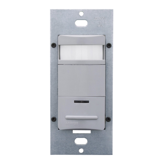
Leviton Cat. No. OSSNL/OSS10-IDx, Designer Wall Switch
Occupancy Sensor with LED NightLight, is designed to detect
motion from a heat-emitting source (such as a person entering
a room) within its field-of-view (monitored space) and either
automatically or manually switches lights ON and OFF (OSSNL)
or manually switches lights ON and automatically switches lights
OFF (OSS10). The controlled lights will remain ON until no motion
is detected and the scheduled time-delay has expired. The LED
NightLight operates separately from controlled room lights and
will turn ON via a photocell when the ambient light in the space
is approximately less than 1 footcandle and turn OFF when the
ambient light exceeds 5 footcandles. The LED NightLight is
adjustable for continuous mode or a dim mode. In the dim mode
the LED dims to approximately 5% of full brightness after 2 minutes
of no occupancy. When in the manual ON switch mode, the LED
NightLight will fade up and return to the adjustable setting when
occupancy is detected and the ambient light level present to the
photocell is less than 1 footcandle. The LED NightLight consumes
less than one half of a watt providing energy savings and guide
lighting when room lights are off. The LED NightLight output is fully
adjustable with a simple dial setting.
OSSNL-IDx is perfect for use in hospitality and health care
facilities with either auto ON or manual ON settings with adjustable
time-delay settings of 30 seconds to 2 hours with LED NightLight.
The OSS10 works well anywhere a manual ON only occupancy
sensor with LED NightLight is desired and has a maximum of
30 minute time-delay setting to conform to California Title 24
requirements. Both sensors are UL listed and have a limited 5-year
warranty.
pASSIvE INFRARED (pIR) TEChNOLOGY DESCRIpTION
The Occupancy Sensor senses motion within its coverage area of
1200 sq. ft maximum and controls the connected lighting. This is
a self-contained device which provides sensing and light control.
The Occupancy Sensor will turn the lights ON when motion is
initially detected (OSSNL Only), and keep the lights ON for as long
as motion is detected. The OSS10 is a manual ON device with
automatic OFF when no occupancy is detected.
The Occupancy Sensor uses a small semiconductor heat detector
that resides behind a multi-zone optical lens. This Fresnel lens
establishes dozens of zones of detection. The Sensor is sensitive
to the heat emitted by the human body. In order to trigger the
Sensor, the source of heat must move from one zone of detection
to another. The device is most effective in sensing motion across
its field-of-view, and less effective sensing motion towards or away
from its field-of-view (refer to Field-of view diagrams). Keep this
in mind when selecting the installation location.
Designer Wall Switch Occupancy Sensor with LED NightLight
Incandescent: 800W @ 120V
Fluorescent: 1200VA @ 120V
Compatible with incandescent lamps, electronic and magnetic low-voltage ballasts, electronic and magnetic ballasts, and fans
DESCRIpTION cont'd
Note that occupancy sensors respond to rapid changes in
temperature, so care should be taken not to mount the device
near a climate control source (i.e. radiators, air exchanges, and air
conditioners). Hot or cold drafts will look like body motion to the device
and will trigger it if the unit is mounted too close. It is recommended
to mount the Occupancy Sensor at least 6 ft. away from the climate
control source. The device can be mounted in a single gang wall box.
In addition, it is also recommended NOT to mount the Occupancy
Sensor directly under a large light source. Large wattage bulbs
(greater than 100W incandescent) give off a lot of heat and switching
the bulb causes a temperature change that can be detected by the
device. Mount the Occupancy Sensor at least 6 ft. away from large
bulbs. If it is necessary to mount the device closer, lower the wattage
of the bulb directly overhead.
INSTALLING YOuR SENSOR
NOTE: Use check boxes
when Steps are completed.
WARNING:
TO AvOID FIRE, ShOCk, OR DEATh;
Step 1
TuRN OFF pOWER at circuit breaker or fuse and test that
power is off before wiring!
Identifying your wiring application
Step 2
(most common):
NOTE: If the wiring in the wall box does not resemble this
configuration, consult a qualified electrician.
1
2
2
1
3
3
4
4
5
Single-pole
3-Way
1. Line (Hot)
1. Line or Load
2. Neutral
(See *IMpORTANT instruction)
3. Ground
2. Neutral
4. Load
3. Ground
4. First Traveler – note color
5. Second Traveler – note color
*IMpORTANT: For 3-Way applications, note that one of the screw
terminals from the old switch being removed will usually be a different
color (Black) or labeled Common. Tag that wire with electrical tape and
identify as the common (Line or Load) in both switch wall boxes.
Single Pole (One Location) or Multi-Location
California Title 24 2005 Compliant
Cat. No. OSSNL/OSS10-IDx
Fluorescent: 2700VA @ 277V
No Minimum Load Required
INSTALLATION INSTRuCTIONS
WARNINGS AND CAuTIONS:
• The OSSNL/OSS10-IDx Occupancy Sensor is intended to replace a standard light switch.
• Do not touch the surface of the lens. Clean outer surface with a damp cloth only.
• Disconnect power at circuit breaker or fuse when servicing, installing or removing fixture.
• Use this device only with copper or copper clad wire. With aluminum wire use only devices marked CO/ALR or CU/AL.
preparing and connecting wires:
Step 3
Strip Gage
5/8"
(measure bare
(1.6 cm)
wire here)
Cut
(if necessary)
• Pull off pre-cut insulation from sensor leads.
• Make sure that the ends of the wires from the wall box are straight
(cut if necessary).
• Remove insulation from each wire in the wall box as shown.
For non-standard wiring applications, refer
to Wire Nut and Conductor Size Chart
WIRE NuT / # OF COND.
COMBINATION ChART
1- #12 w/ 1 to 3 #14, #16 or #18
2- #12 w/ 1 or 2 #16 or #18
1- #14 w/ 1 to 4 #16 or #18
2- #14 w/ 1 to 3 #16 or #18
Installing your Sensor -
Step 4
Single-pole Application:
NOTE: Sensor requires a neutral connection in order
to operate. Use the ground wire in the electricl box for
ground connection. If there is no ground wire, ensure
electrical box is grounded and attach ground wire to box
with a screw.
Sensor
Black
1
2
Electrical
White
Tape
Insert wires
Blue
4
straight
then twist
Green
3
clockwise
Sensor
Blue
Black
Black (Hot)
Black
White
Load
Line
120/277VAC, 60Hz
Green
Ground
White
Neutral (White)
WIRING SENSOR:
Connect wires per WIRING DIAGRAM as follows:
Screw wire connector on clockwise making sure there are no bare
conductors below the wire connectors. Secure each connector with
electrical tape.
• Green or bare copper wire in wall box to Green lead.
• Line Hot wall box wire to Black lead.
• Load wall box wire to Blue lead.
• Line Neutral wall box wire to White lead.
NOTE: Allow approximately 30 seconds for warm-up after connected.
Supplemental: 1/4hp @ 120V
Installing your Sensor -
Step 5
3-Way Wiring Application:
NOTE: Sensor requires a neutral connection in order
to operate. Use the ground wire in the electrical box for
ground connection. If there is no ground wire, ensure
electrical box is grounded and attach ground wire to box
with a screw.
Sensor 1
Sensor 2
Black
Black
1
2
2
4
4
White
White
Blue
Blue
1
5
5
Green
Green
3
3
Insert wires
Electrical
straight
Tape
then twist
clockwise
Sensor 1
Sensor 2
Black (Hot)
Black
Blue
Blue
Black
Black
White
White
Line
120/277VAC, 60Hz
Load
Green
Green
Ground
Ground
White
Neutral (White)
NOTE: Sensor 1 must be installed in a wall box that has both a LINE
Hot and a Neutral connection. Sensor 2 must be installed in a wall box
that has both a Load and a Neutral connection.
If you are unsure about any part of these instructions, consult a
qualified electrician.
WIRING SENSOR 1:
Connect wires per WIRING DIAGRAM as follows:
Screw wire connector on clockwise making sure there are no bare
conductors below the wire connectors. Secure each connector with
electrical tape.
• Green or bare copper wire in wall box to Sensor 1 Green lead.
• Line Hot (common) wall box wire identified (tagged) when removing
old switch and First Traveler from Sensor 2 to Sensor 1 Black lead.
• Second Traveler wall box wire from Sensor 2 to Sensor 1 Blue lead.
• Line Neutral wall box wire to Sensor 1 White lead.
WIRING SENSOR 2:
Connect wires per WIRING DIAGRAM as follows:
Screw wire connector on clockwise making sure there are no bare
conductors below the wire connectors. Secure each connector with
electrical tape.
• Green or bare copper wire in wall box to Sensor 2 Green lead.
• Load wall box wire identified (tagged) when removing old switch
and Second Traveler from Sensor 1 to Sensor 2 Blue lead.
• First Traveler Line Hot from Sensor 1 to Sensor 2 Black lead.
• Second Traveler wall box wire from Sensor 2 to Sensor 1 Blue lead.
• Line Neutral wall box wire to Sensor 2 White lead.
NOTE: Allow approximately 30 seconds for warm-up after connected.
Testing your Sensor prior to completely
Step 6
mounting in wall box:
Wall surface
Mounting
screws
(2 places)
Sensor
NOTE: Dress wires with a bend as shown in diagram to relieve
stress when mounting device.
• Position all wires to provide room in outlet wall box for device.
• Partially secure device using long mounting screws provided.
• Restore power at circuit breaker or fuse.
• The LED indicator will flash after power is applied. Allow
approximtely 30 seconds for charge-up. After 30 seconds the
lights will turn ON. If the lights turn ON and the LED blinks
when a hand is waved in front of the lens, then the Sensor was
installed properly.
If lights do not turn ON, refer to the TROuBLEShOOTING
section.
NOTE: Cat. No. OSSNL/OSS10-IDx is factory preset to work
without any adjustments. If you desire to change the factory
settings, refer to FEATuRES AND SETTINGS section).
NOTE: To avoid PERMANENT DAMAGE to the unit, be careful
NOT TO OVERTURN the control knobs or levers when setting
the Sensor. The controls can be accessed by removing the
wallplate (if applicable) and control panel cover (refer to Sensor
Features Diagram). Use a small straight blade screwdriver to
adjust knobs and blinder levers.
NOTE: DO NOT press in on blinder levers or use excessive
force (refer to Sensor Features Diagram).
• Attach the Control Panel cover when the desired settings are
complete.
FEATuRES AND SETTINGS:
BLINDERS: The blinders can narrow the field-of-view of the device
to prevent unwanted activation from traffic in adjacent space. There
are two blinders, and each operate independently. To operate the
blinders, use a finger or small screwdriver to move the blinder
adjustment levers toward or away from the center of the device.
The blinder levers are found above the control knobs and below the
text 'BLINDERS' on the control panel. With both levers moved fully
towards the center, the field-of-view is narrowed to 32°. With both
levers moved fully away from the center, the field-of-view is at a
maximum 180° (refer to Sensor Features Diagram).
Advertisement
Table of Contents

Related Manuals for Leviton OSS10-IDx


Summary of Contents for Leviton OSS10-IDx
- Page 1 INSTALLATION INSTRuCTIONS WARNINGS AND CAuTIONS: • The OSSNL/OSS10-IDx Occupancy Sensor is intended to replace a standard light switch. • Do not touch the surface of the lens. Clean outer surface with a damp cloth only. • Disconnect power at circuit breaker or fuse when servicing, installing or removing fixture.
- Page 2 Leviton Manufacturing Co., Inc., Att: Quality Assurance Department, 59-25 Little Neck parkway, Little Neck, New York 11362-2591. This warranty excludes and there is disclaimed liability for labor for removal of this product or reinstallation.
Need help?
Do you have a question about the OSS10-IDx and is the answer not in the manual?
Questions and answers