Table of Contents
Advertisement
Quick Links
• Sensor has a 360 field-of-view with 530 sq. ft. of coverage.
• LED indicator light blinks when sensor detects motion.
• Cat. Nos. ODC0S-I1 and ODC0S-I7 have four 14AWG 6" pre-stripped color coded leads.
• Screw on cover plate shields mounting hardware and adjustment control.
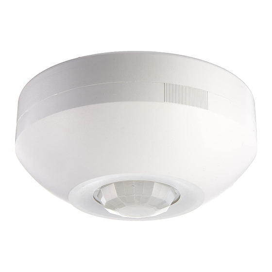
Ceiling Mount
Occupancy Sensor
The Leviton Passive Infrared Ceiling Mount Occupancy Sensor, Cat. Nos. ODC0S-I1 and ODC0S-I7, monitors
Cat. No. ODC0S-I1
rapid changes in temperature within its field-of-view (see Figures 3 and 4) and is designed to turn lights ON when
temperature changes (such as a person entering a room) is detected, and OFF when occupancy is no longer
Rated: 120VAC, 60Hz
detected and the scheduled time-delay setting has expired.
Incandescent
Since Cat. Nos. ODC0S-I1 and ODC0S-I7 respond to temperature changes, care should be taken not to mount the
1000W @ 120V
sensor directly above a heat source, or where hot/cold drafts (i.e. from an HVAC duct) will blow directly on the
sensor, or where adjacent traffic, (i.e. hallway activity) will be within the sensor's field-of-view.
Inductive Fluorescent
In addition, it is also recommended NOT to mount the Occupancy Sensor directly under a large light source. Large
1000VA @ 120V
wattage bulbs (greater than 100W incandescent) give off a lot of heat and switching the bulb causes a temperature
Power Consumption: 4W
change that can be detected by the device. Mount the Occupancy Sensor at least 6 ft. away from large bulbs.
Cat. No. ODC0S-I7
WARNING:
Rated: 277VAC, 60Hz
AND REGULATIONS.
WARNING:
Fluorescent
ELECTRICIAN.
2700VA @ 277V
WARNING:
Power Consumption: 4W
EQUIPMENT, DO NOT INSTALL TO CONTROL A TRANSFORMER-OPERATED DEVICE(S) OTHER THAN
APPROPRIATE LOW-VOLTAGE LIGHTING.
OTHER CAUTIONS:
Installation Instructions
1. USE THIS DEVICE ONLY WITH COPPER OR COPPER CLAD WIRE. WITH ALUMINUM WIRE USE ONLY
DI-000-ODC0S-00A
2. DO NOT ATTEMPT TO DISASSEMBLE OR REPAIR. DISCONNECT POWER WHEN SERVICING OR
TO INSTALL:
LIMITED FIVE YEAR WARRANTY AND EXCLUSIONS
1.
Leviton warrants to the original consumer purchaser and not for the benefit
of anyone else that this product at the time of its sale by Leviton is free of
2. Determine the best location for the sensor. Install the sensor at least 3 ft. away from fluorescent ballasts and
defects in materials and workmanship under normal and proper use for
five years from the purchase date. Leviton's only obligation is to correct
such defects by repair or replacement, at its option, if within such five
year period the product is returned prepaid, with proof of purchase date,
3. Cut a 1-1/2" diameter hole in the ceiling beneath the single-gang box installed.
and a description of the problem to: Leviton Manufacturing Co., Inc.,
4. Remove approximately 3/4" (1.9 cm) of insulation
Att: Quality Assurance Department, 59-25 Little Neck Parkway, Little
Neck, New York 11362-2591. This warranty excludes and there is
disclaimed liability for labor for removal of this product or reinstallation.
5. Connect wires per appropriate WIRING DIAGRAM as
This warranty is void if this product is installed improperly or in an improper
environment, overloaded, misused, opened, abused, or altered in any
manner, or is not used under normal operating conditions or not in
accordance with any labels or instructions. There are no other or implied
warranties of any kind, including merchantability and fitness of a particular
purpose, but if any implied warranty is required by the applicable
jurisdiction, the duration of any such implied warranty, including
6. Remove the face plate and set it aside (see Figures
merchantability and fitness for a particular purpose, is limited to five years.
Leviton is not liable for incidental, indirect, special, or consequential damages,
including without limitation, damage to, or loss of use of, any equipment, lost
sales or profits or delay or failure to perform this warranty obligation. The
7. Restore power at circuit breaker or fuse.
remedies provided herein are the exclusive remedies under this warranty,
whether based on contract, tort or otherwise.
For Technical Assistance Call:
1-800-824-3005 (U.S.A. Only)
Time-Delay: Settings should be determined during the installation period. This adjustment controls the amount of
www.leviton.com
time the lights stay ON after the last detected motion. You may select settings varying from 20 seconds (-) to 15 minutes
(+) and any time in between.
NOTE: After power is turned ON from the circuit breaker or fuse, allow two minutes for this unit to warm up before
performing Time-Delay settings.
Ambient Light: This adjustment allows you to determine at what minimum Ambient light level the device will
operate. You may select settings from always operating (day and night) to operating only when the Ambient Light
level is less than 3 lux, or anywhere in between. The lights will turn ON when the unit senses motion and the
Ambient Light reaches your desired level.
DI-000-ODC0S-00A
DI-000-ODC0S-00A
1
FEATURES
DESCRIPTION
INSTALLATION INSTRUCTIONS
TO BE INSTALLED AND/OR USED IN ACCORDANCE WITH APPROPRIATE ELECTRICAL CODES
IF YOU ARE NOT SURE ABOUT ANY PART OF THESE INSTRUCTIONS, CONSULT A QUALIFIED
TO AVOID OVERHEATING AND POSSIBLE DAMAGE TO THIS DEVICE AND OTHER
DEVICES MARKED CO/ALR OR CU/AL.
CHANGING BULBS. CLEAN OUTER SURFACE WITH DAMP CLOTH ONLY.
WARNING:
TO AVOID FIRE, SHOCK, OR DEATH; TURN OFF POWER AT CIRCUIT BREAKER OR FUSE
AND TEST THAT THE POWER IS OFF BEFORE WIRING!
HVAC ducts, and at least 4 ft. away from incandescent fixtures and HVAC diffusers . Install in a standard NEMA
single-gang box.
from circuit wires.
follows: Twist strands of each lead tightly and, with
circuit conductors, push firmly into the appropriate
wire connector. Screw connector on clockwise making
sure that no bare wire shows below the connector.
Secure each wire connector with electrical tape.
1A and 1B). Set Time-Delay and Ambient Light as
detailed in the SETTINGS section.
INSTALLATION IS COMPLETE.
SETTINGS
4/7/00, 2:50 PM
Figure 1A
Figure 1B
Advertisement
Table of Contents

Related Manuals for Leviton ODC0S-I1


Summary of Contents for Leviton ODC0S-I1
- Page 1 Incandescent Since Cat. Nos. ODC0S-I1 and ODC0S-I7 respond to temperature changes, care should be taken not to mount the 1000W @ 120V sensor directly above a heat source, or where hot/cold drafts (i.e. from an HVAC duct) will blow directly on the sensor, or where adjacent traffic, (i.e.
- Page 2 DELAY (see SETTINGS section) . DI-000-ODC0S-00A Figure 4 26 Ft. Time Light 3.7 M 3 FT 7 FT 13 FT Wiring Diagram 1 - Cat. No. ODC0S-I1 Black Blue Sensor Blue Black Load White White Wiring Diagram 2 - Cat. No. ODC0S-I7...
Need help?
Do you have a question about the ODC0S-I1 and is the answer not in the manual?
Questions and answers