Advertisement
Quick Links
WARNINGS AND CAUTIONS:
• To be installed and/or used in accordance with appropriate electrical codes and regulations.
• If you are unsure about any part of these instructions, consult a qualified electrician.
• Controlling a load in excess of the specified ratings will damage the unit and pose risk of fire, electric shock, personal injury or death.
Check your load ratings to determine suitability for your application.
• Do not install this unit to control a receptacle.
TOOLS NeeDeD TO INSTALL yOUR SeNSOR
Slotted/Phillips Screwdriver
Electrical Tape
Pliers
Cutters
Small Slotted Screwdriver
FeATUReS
• Leviton's Decora
style design
®
• Sensor can be ganged together with other units in a multiple-switch
wall plate.
• Self-Adaptive Technology adjusts to occupancy patterns of use in auto
adapt mode.
• The Adapting Time-out walk-through feature prevents lights from
remaining ON for an extended period after only a momentary
occupancy.
• Switches two separate load circuits.
• Two (MD and GD models) convenient Push-Buttons provide manual
ON/OFF switching at any time.
• Adjustable horizontal field of view.
• Integrated photocell prevents lights from turning ON when room is
adequately illuminated by natural light.
• True Zero-Cross for primary relay provides maximum contact life and
compatibility with electronic ballasts.
• Dual detection technology, both Passive Infrared and Ultrasonic. Can
be configured as Ultrasonic Only by disabling Passive Infrared.
DeSCRIpTION
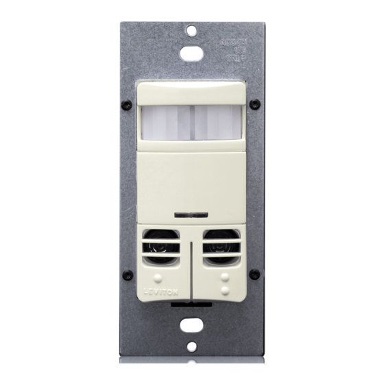
Leviton's Designer Multi-Technology Wall Switch Occupancy Sensor,
Cat. No. OSSMD, is designed to detect motion using the passive infrared
(PIR) sensor from sources (such as a person entering a room) within its
field-of-view (monitored space) and automatically switch lights ON. The
Occupancy Sensor senses motion within its maximum coverage area of
2400 sq. ft (223 m
2
). The Ultrasonic (US) sensors work with the PIR to
keep the lights ON when occupied. The controlled lights will remain ON
until no motion is detected and the scheduled time-delay has expired, at
which point the lights will be turned OFF. In adapting time-out mode the
sensor adapts its time delay settings to the occupancy patterns of a room.
The OSSMD-MD is an Occupancy Sensor that is designed to control two
separate lighting control circuits from a single unit. This allows the user to
replace two switches with a single unit that will provide the convenience
and energy savings of an occupancy sensor. It is a dual relay device,
relay one can be Auto ON or Manual ON and relay two is Manual ON
only. The device contains a photocell that provides an Ambient Light Hold
Off function for relay number one. Both relays operate as Auto OFF. The
device can be configured for either Ultrasonic with PIR or Ultrasonic Only
modes of operation.
The OSSMD-GD has all the functionality of the OSSMD-MD without a
neutral conductor. It is intended for use in retrofit applications where a
neutral is not available in the wall box.
The OSSMD-FT model is intended for applications such as a commercial
bathroom where a convenience exhaust fan must be controlled. The
two relays turn ON in tandem but remain ON for different durations.
The device can be configured to be either in the Auto ON or Manual
ON modes. The Auto ON mode utilizes the sensor technology to turn
ON while the single push button on the front of the device provides the
Manual ON activation. A fixed time delay OFF of 10 minutes, which starts
when the first relay turns off, will apply to the second relay in both of these
modes of operation. It can be configured for either Ultrasonic with PIR
or Ultrasonic Only modes of operation. This device requires a neutral
conductor.
Cat. No. OSSMD is eTL listed, ceTL listed and conforms to California
Title 24 requirements.
The PIR Occupancy Sensor uses a small semiconductor heat detector
that resides behind a multi-zone optical lens. This Fresnel lens
establishes dozens of zones of detection. The Sensor is sensitive to the
heat emitted by the human body. In order to initially trigger the Sensor,
Multi-Technology Designer Wall Switch Occupancy Sensor with Dual Relays
Incandescent/Tungsten: 800W @ 120V Primary/Secondary
Ballast: 2700VA @ 277V Primary - 1200VA @ 277V Secondary
Compatible with incandescent lamps, low-voltage lighting with electronic and magnetic transformers, electronic and magnetic fluorescent ballasts, and fans.
the source of heat must move from one zone of detection to another. The
device is most effective in sensing motion across its field-of-view and it is
less effective sensing motion towards or away from its field-of-view. Keep
this in mind when selecting the installation location (refer to Field-of-View
diagrams).
The US Occupancy Sensor uses a non-audible, high frequency (40kHz)
to sense Doppler shifts caused by motion in the space. The US is more
sensitive to small motion and does not rely on line of sight for detection. If
both sensors have not detected any motion for the set timeout period, the
relays and their corresponding loads will be turned OFF.
Note that occupancy sensors respond to rapid changes in temperature, so
care should be taken not to mount the device near a climate control source
(i.e. radiators, air exchanges, and air conditioners). Hot or cold drafts will
look like body motion to the device and will trigger it if the unit is mounted too
close. It is recommended to mount the Occupancy Sensor at least 6 feet
away from a climate control source.
In addition, it is also recommended NOT to mount the Occupancy Sensor
directly under a large light source. Large wattage bulbs (greater than
100W incandescent) give off a lot of heat and switching the bulb causes a
temperature change that can be detected by the device.
Mount the Occupancy Sensor at least 6 ft. away from large bulbs. If it is
necessary to mount the device closer, lower the wattage of the bulb directly
overhead.
INSTALLING yOUR SeNSOR
NOTe: Use check boxes
when Steps are completed.
WARNING:
TO AVOID FIRe, SHOCk, OR DeATH; TURN
Step 1
OFF pOWeR at circuit breaker or fuse and test that power is
off before wiring!
Identifying your wiring application
Step 2
(most common):
1. Line (Hot)
2. Neutral
3. Ground
4. Load
1
5. Secondary Load
2
3
4
5
Two Circuit (One Location) or Multi-Location
California Title 24 2005 Compliant
Cat. No. OSSMD-MD, OSSMD-FT, OSSMD-GD
Ballast: 1200VA @ 120V Primary - 800VA @ 120V Secondary
Motor: 1/4hp @ 120V Primary/Secondary
Operating Temperature Range: 0°C to 50°C
Relative Humidity: 20% to 90% non-condensing
No Minimum Load Required
INSTALLATION INSTRUCTIONS
WARNINGS AND CAUTIONS:
• Do not touch the surface of the lens. Clean outer surface with a damp cloth only.
• Disconnect power at circuit breaker or fuse when servicing, installing or removing fixture.
• Use this device only with copper or copper clad wire. With aluminum wire use only devices marked CO/ALR or CU/AL.
preparing and connecting wires:
Step 3
Strip Gage
9/16"
(measure bare
(1.4 cm)
wire here)
Cut
(if necessary)
• Pull off pre-cut insulation from sensor leads.
• Make sure that the ends of the wires from the wall box are straight
(cut if necessary).
• Remove insulation from each wire in the wall box as shown.
Installing your Sensor - Single Location
Step 4
Application:
WARNING:
If you are unsure about any part of these instructions,
consult a qualified electrician.
NOTe: Allow 1 minute for warm-up after connecting and energizing.
OSSMD-GD Wiring Methods
NOTe: The occupancy sensor Cat. No. OSSMD-GD does not require a
neutral connection in order to operate. It must have a ground connection.
Use the ground wire in the electrical box for ground connection. If there is
no ground wire, ensure electrical box is grounded and attach ground wire
to box by an approved connection method.
Sensor
Red
Hot (Black)
Phase 1
Black
Red
Blue
Line
Green
Secondary
120/277VAC
Ground
Load
Primary
60Hz
Load
Neutral (White)
Sensor
Red (To Phase 2)
Hot (Black)
Red
Phase 1
Black
Blue
Line
Green
Secondary
120/277VAC
Ground
Load
Primary
60Hz
Load
Neutral (White)
OSSMD-MD Wiring Methods
NOTe: The occupancy sensor Cat. No. OSSMD-MD requires a neutral
connection to operate. Use the ground wire in the electrical box for
ground connection. If there is no ground wire, ensure electrical box is
grounded and attach ground wire to box with a screw.
Sensor
Red
Hot (Black)
Phase 1
Black
Red
White
Blue
Line
Green
Secondary
120/277VAC
Ground
Load
Primary
60Hz
Load
Neutral (White)
Sensor
Red (To Phase 2)
Hot (Black)
Red
Phase 1
Black
White
Blue
Line
Green
Secondary
120/277VAC
Ground
Load
Primary
60Hz
Load
Neutral (White)
OSSMD-FT Wiring Methods
NOTe: The occupancy sensor Cat. No. OSSMD-FT requires a neutral
connection to operate. Use the ground wire in the electrical box for
ground connection. If there is no ground wire, ensure electrical box is
grounded and attach ground wire to box with a screw.
Sensor
Red
Hot (Black)
Phase 1
Black
Red
White
Blue
Line
Fan/
Green
Secondary
120/277VAC
Ground
Load
Primary
60Hz
Load
Neutral (White)
Sensor
Red (To Phase 2)
Hot (Black)
Red
Phase 1
Black
White
Blue
Line
Fan/
Green
120/277VAC
Secondary
Ground
Primary
Load
60Hz
Load
Neutral (White)
DI-000-OSSMD-00A
Installing your Sensor - Two Location Wiring
Step 5
Application:
WARNING:
If you are unsure about any part of these instructions,
consult a qualified electrician.
NOTe: Either sensor can turn the lights ON. Both sensors must
time-out to OFF, or both manual buttons must be pressed for the
lights to turn OFF.
NOTe: Allow 1 minute for warm-up after connecting and energizing.
NOTe: Both occupancy sensors Cat. No. OSSMD-MD and OSSMD-FT
require a neutral connection in order to operate. Use the ground wire in
the electrical box for ground connection. If there is no ground wire, ensure
electrical box is grounded and attach ground wire to box with a screw.
Sensor 1
Sensor 2
Red
Red
Hot (Black)
Black
Phase 1
Black
Secondary
Red
Red
Load
White
Blue
Blue
White
Line
120/277VAC
Green
60Hz
Ground
Primary
Load
Green
Ground
Neutral (White)
Sensor 1
Sensor 2
To Phase 2
Red
Red
Hot (Black)
Black
Phase 1
Black
Red
Red
Secondary
White
Load
Blue
Blue
White
Line
120/277VAC
Green
Primary
60Hz
Ground
Load
Green
Ground
Neutral (White)
Advertisement

Related Manuals for Leviton OSSMD-FT


Summary of Contents for Leviton OSSMD-FT
- Page 1 It is intended for use in retrofit applications where a neutral is not available in the wall box. The OSSMD-FT model is intended for applications such as a commercial bathroom where a convenience exhaust fan must be controlled. The two relays turn ON in tandem but remain ON for different durations.
- Page 2 Leviton is not liable for incidental, indirect, special, or consequential damages, including without limitation, damage to, or loss of use of, any equipment, lost sales or profits or delay or failure to perform this warranty obligation.
Need help?
Do you have a question about the OSSMD-FT and is the answer not in the manual?
Questions and answers