Table of Contents
Advertisement
DI-000-IPP15-02A
WARNINGS AND CAUTIONS:
• To be installed and/or used in accordance with appropriate electrical codes and regulations.
• If you are unsure about any part of these instructions, consult a qualified electrician.
• Controlling a load in excess of the specified ratings will damage the unit and pose risk of fire, electric shock, personal injury or death.
Check your load ratings to determine suitability for your application.
• Do not install this unit to control a receptacle.
Tools needed to install your Sensor:
Slotted/Phillips Screwdriver
Electrical Tape
Pliers
Pencil
Cutters
Ruler
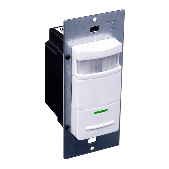
DESCRIPTION
Leviton's Cat. No. IPP15-1L Manual-On Occupancy Sensor acts
like a regular wall switch taking place of your existing wall
switch. It has added benefit that if you forget to turn the light
OFF, the lights will turn OFF automatically if motion is not
detected within its coverage area. The Sensor is used to provide
energy savings and convenience in a variety of residential
applications including:
Bathrooms
Basement
Laundry Room
Garages
Utility Rooms
Dining Room
Hallways
The IPP15-1L, which features a Manual-ON operation, is
California Title 24 2005 compliant. The unit turns off manually
or in absence of motion according to the timeout selected. The
unit installs in place of a single-pole or 3-way wall switch and fits
in a standard wall box. The unit can be used for switching
incandescent and fluorescent and low voltage lighting with
electronic or magnetic ballasts.
The Sensor senses motion within its coverage area of 900 sq. ft.
(83.6 m
2
) maximum and controls the connected lighting. The
Sensor uses a small semiconductor heat detector that resides
behind a multi-zone optical lens. This Fresnel lens establishes
dozens of zones of detection. The sensor is sensitive to the heat
emitted by the human body. In order to keep the lights ON, the
source of heat must move from one zone of detection to another.
The device is most effective in sensing motion across its field-of-
view, and less effective sensing motion towards or away from its
field-of-view (refer to Field-Of-View Diagrams). Obstructions
such as furniture, windows, glass shower doors, etc... may
prevent the sensor from detecting motion. Keep this in mind when
selecting the installation location.
Note that the sensor responds to rapid changes in temperature,
so care should be taken not to mount the device near a climate
control source (i.e. radiators, air exchanges, and air
conditioners). Hot or cold drafts will look like body motion to the
device and will trigger it if the unit is mounted too close. It is
recommended to mount the Sensor at least 6 ft. away from
the climate control source. The device can be mounted in a
single gang wall box.
In addition, it is also recommended NOT to mount the Sensor
directly under a large light source. Large wattage bulbs (greater
than 100W incandescent) give off a lot of heat and switching the
bulb causes a temperature change that can be detected by the
device. Mount the Sensor at least 6 ft. away from large bulbs. If
it is necessary to mount the device closer, reduce the wattage of
the bulb directly overhead.
Single Pole (One location) or 3-Way (Multi-location)
Decora
Incandescent: 1800W-15A @ 120V
Compatible with incandescent lamps, electronic and magnetic low-voltage ballasts, electronic and magnetic ballasts, and fans.
INSTALLING YOUR SENSOR
NOTE: Use check boxes
when Steps are completed.
WARNING:
Step 1
TO AVOID FIRE, SHOCK, OR DEATH;
TURN OFF POWER at circuit breaker or fuse and test
that power is off before wiring!
OFF
ON
OFF
ON
OFF
ON
OFF
ON
OFF
ON
OFF
ON
OFF
ON
OFF
ON
OFF
ON
OFF
ON
OFF
ON
OFF
ON
Identifying your wiring application (most common):
Step 2
NOTE: If the wiring in the wall box does not resemble
this configuration, consult a qualified electrician.
Single Pole
3-Way
1. Line (Hot)
1. Line or Load (see important
2. Neutral
instruction below)
3. Ground
2. Neutral
2
1
4. Load
3. Ground
4. First Traveler - note color
5. Second Traveler - note color.
3
NOTE: For matching switch
4
remote w/LED installation, the
First Traveler becomes Line Hot.
Preparing and connecting wires:
Step 3
This sensor can be wired using side wire terminal screws or
through backwire openings. Choose appropriate wire
stripping specifications accordingly.
Strip Gage
Cut
(measure bare
(if necessary)
wire here)
Side Wire
Back Wire (either
Connection
hole may be used)
Side wire terminals
Back wire openings
accept #14 AWG
use #14-12 AWG
solid wire copper
solid wire copper
only .
only .
®
Manual-ON Occupancy Sensor
California Title 24 2005 Compliant
Cat. No. IPP15-1L
Fluorescent: 1800VA-15A @ 120V
No Minimum Load Required
INSTALLATION INSTRUCTIONS
WARNINGS AND CAUTIONS:
• The IPP15 Manual-On Occupancy Sensor is intended to replace a standard light switch.
• Do not touch the surface of the lens. Clean outer surface with a damp cloth only.
• Disconnect power at circuit breaker or fuse when servicing, installing or removing fixture.
• Use this device only with copper or copper clad wire. With aluminum wire use only devices marked CO/ALR or CU/AL.
Step 3 cont'd
• Make sure that the ends of the wires from the wall box are
straight (cut if necessary).
• Remove insulation from each wire in the wall box as shown.
• For Single-Pole Application, go to Step 4a.
• For 3-Way Coordinating Remote (no LED) Application, go to Step 4b.
• For 3-Way Matching Remote (with LED) or IPP0R Sensor Remote
Application, go to Step 4c.
Installing your Sensor –
Step 4a
Single-Pole Wiring Application:
Terminal
Screw marked
White (WH)
Terminal
Screw marked
Black (BK)
Terminal
Screw marked
1
2
Yellow/Red
Terminal
(YL/RD)
Screw marked
Red (RD)
3
4
Terminal Label:
5
Use Terminal for 3-Way or More Applications Only.
For Single-Pole Applications, Do Not Remove This
Label.
Sensor
WH
RD
Black
Load
White
5/8"
(1.6 cm)
WIRING SENSOR:
Connect wires per WIRING DIAGRAM as follows:
• Green or bare copper wire in wall box to Green terminal screw.
• Line Hot wall box wire to terminal screw marked "BK".
• Load wall box wire to terminal screw marked "RD".
• Line Neutral wall box wire to terminal screw marked "WH".
• Sensor terminal screw marked "YL/RD" should have Red
insulation label affixed.
NOTE: If insulating label is not affixed to terminal screw
marked "YL/RD", use electrical tape to cover.
• Proceed to Step 5.
Supplemental: 1/2hp @ 120V
3-Way Wiring with Vizia
Step 4b
Remote (no LED) Application:
TM
Vizia
Switch Remote
3
5
TM
Vizia
Coordinating Switch
Remote (no LED)
WH
1
2
Black
RD
(unused)
Load
3
4
White
WIRING SENSOR:
Connect wires per WIRING DIAGRAM as follows:
NOTE: The sensor must be installed in a wall box that has a Line Hot connection.
NOTE: Maximum wire length from sensor to all installed remotes cannot
exceed 300 ft (90 m).
• Green or bare copper wire in wall box to Green terminal screw.
• Line Hot (common) wall box wire identified (tagged) when removing old switch
Hot (Black)
to terminal screw marked "BK".
BK
• First Traveler wall box wire to terminal screw marked "RD" (note wire color).
Green
Ground
• Remove Red insulating label from terminal screw marked "YL/RD".
• Second Traveler wall box wire to terminal screw marked "YL/RD" (note wire color).
YL/RD
Line
This traveler from the sensor must go to the terminal screw on the remote
Use Terminal for 3-Way or
120VAC, 60Hz
marked "YL/RD".
More Applications Only.
For Single-Pole Applications,
• Line Neutral wall box wire to terminal screw marked "WH".
Do Not Remove This Label.
WIRING COORDINATING REMOTE:
Neutral (White)
Connect wires per WIRING DIAGRAM as follows:
NOTE: "BK" and "RD" terminals on coordinating remote are unused. Tighten both screws.
NOTE: Maximum wire length from sensor to last remote is 300 ft (90 m).
• Green or bare copper wire in wall box to Green terminal screw.
• Load wall box wire identified (tagged) when removing old switch to First
Traveler (note color as above).
• Second Traveler wall box wire (note color as above) to terminal screw marked
"YL/RD". This traveler from the remote must go to the terminal screw on the sensor
marked "YL/RD".
• Remove White insulating label from terminal screw marked "WH".
• Line Neutral wall box wire to terminal screw marked "WH".
• Proceed to Step 5.
TM
Coordinating
Terminal
Coordinating
Sensor
Screw marked
White (WH)
1
Terminal
Screw marked
2
2
Black (BK)
1
3
4
Terminal
4
Screw marked
5
Yellow/Red
(YL/RD)
Terminal
Screw marked
Red (RD)
Sensor
Hot (Black)
BK
WH
(unused)
BK
Green
Green
Ground
Ground
YL/RD
YL/RD
Line
RD
120VAC, 60Hz
Neutral (White)
Advertisement
Table of Contents

Related Manuals for Leviton IPP15-1L


Summary of Contents for Leviton IPP15-1L
- Page 1 Ruler Step 1 DESCRIPTION Leviton’s Cat. No. IPP15-1L Manual-On Occupancy Sensor acts like a regular wall switch taking place of your existing wall switch. It has added benefit that if you forget to turn the light OFF, the lights will turn OFF automatically if motion is not detected within its coverage area.
- Page 2 years.
Need help?
Do you have a question about the IPP15-1L and is the answer not in the manual?
Questions and answers