Table of Contents
Advertisement
Advertisement
Table of Contents

Related Manuals for Fuji Electric FRENIC-Lift


Summary of Contents for Fuji Electric FRENIC-Lift
- Page 1 LM2A series Reference Manual INR-SI47-1909a-E...
- Page 2 In no event will Fuji Electric Co., Ltd. be liable for any direct or indirect damages resulting from the application of the information in this manual.
- Page 3 The table below lists the other materials related to the use of the FRENIC-Lift (LM2A). Read them in conjunction with this manual as necessary.
- Page 4 How this manual is organized This manual contains Chapters 1, 2, and 3. Chapter 1 BLOCK DIAGRAMS FOR CONTROL LOGIC This chapter describes the main block diagrams for the control logic of the FRENIC-Lift (LM2A) series of inverters. Chapter 2 FUNCTION CODES This chapter contains overview lists of nine groups of function codes available for the FRENIC-Lift (LM2A) series of inverters and details of each function code.
- Page 5 CONTENTS Chapter 1 BLOCK DIAGRAMS FOR CONTROL LOGIC Symbols Used inside the Block Diagrams and their meanings..............1-1 Reference Speed (pre-ramp) Command Generator ..................1-2 Reference Torque Command Generator ....................1-3 Drive Command Controller ........................1-4 Chapter 2 FUNCTION CODES Function Code Tables ..........................
- Page 6 Chapter 1 BLOCK DIAGRAMS FOR CONTROL LOGIC This chapter describes the main block diagrams for the control logic of the FRENIC-Lift (LM2A). Contents 1.1 Symbols Used inside the Block Diagrams and their meanings ..............1-1 1.2 Reference Speed (pre-ramp) Command Generator ..................1-2 1.3 Reference Torque Command Generator ......................
- Page 8 1.1 Symbols Used inside the Block Diagrams and their meanings FRENIC-Lift (LM2A) series of inverters for lifting machines such as elevators are equipped with a number of function codes to match a variety of motor operations required in your system. Refer to Chapter 2 "FUNCTION CODES"...
- Page 9 1.2 Reference Speed (pre-ramp) Command Generator Figure 1.1 Block Diagram of Reference Speed (pre-ramp) Command Generator...
- Page 10 1.3 Reference Torque Command Generator 1.3 Reference Torque Command Generator Figure 1.2 Block Diagram of Reference Torque Command Generator...
- Page 11 1.4 Drive Command Controller Figure 1.3 Block Diagram of Drive Command Controller...
- Page 12 Chapter 2 FUNCTION CODES This chapter contains overview lists of nine groups of function codes available for the FRENIC-Lift (LM2A) series of inverters and details of each function code. Contents 2.1 Function Code Tables ..........................2-1 2.2 Before setting the function code ....................... 2-22 2.3 Overview of Function Codes ........................
- Page 14 2.1 Function Code Tables 2.1 Function Code Tables Function codes enable the FRENIC-Lift (LM2A) series of inverters to be set up to match your system requirements. Each function code consists of a 3-letter alphanumeric string. The first letter is an alphabet that identifies its group and the following two letters are numerals that identify each individual code in the group.
- Page 15 Similarly, if the BX (data = 1007) is assigned, turning BX off will make the motor coast to a stop. Control mode The FRENIC-Lift (LM2A) series of inverters supports the following control modes. - Vector control with PG for asynchronous motor - Vector control with PG for synchronous motor...
- Page 16 2.1 Function Code Tables Corresponding software version Function code list also shows software version in which the function was added. If software version column is left blank means that the function is available since the first version. The software version can be checked by the followings. - Maintenance screen (PRG >...
- Page 17 The following tables list the function codes available for the FRENIC-Lift (LM2A) series of inverters. F codes: Fundamental Functions Code Name Data setting range Data Protection Disable data protection (Function code data can be edited) Enable data protection Note: This setting is effective if H99 = 0000...
- Page 18 2.1 Function Code Tables E codes: Extension Terminal Functions Code Name Data setting range Command Assignment to: Selecting function code data assigns the corresponding function to terminals [X1] to [X8] as listed below. [X1] [X2] Setting the value of 1000s in parentheses( ) shown below [X3] assigns a negative logic input to a terminal.
- Page 19 Code Name Data setting range Signal Assignment to Selecting function code data assigns the corresponding (Transistor signal) function to terminals [Y1] to [Y2], [Y3A/C] to [Y5A/C], [Y1] and [30A/B/C] as listed below. [Y2] Setting the value of 1000s in parentheses ( ) shown below E22 (Relay contact signal) assigns a negative logic output to a terminal.
- Page 20 2.1 Function Code Tables Code Name Data setting range Speed Arrival (FAR) (Hysteresis) (Equivalent with 0.00 to 200.00 Hz) Variable 14.5 0.00 to 6000 Speed Detection (FDT) (Detection level) (Equivalent with 0.00 to 200.00 Hz) Variable 1450 0.00 to 6000 (Hysteresis) Variable 14.5...
- Page 21 C codes: Control Functions Code Name Data setting range Battery Operation (Input power limit level) 0 to 100 OFF(32767): Torque limit level is F44. (Limit time) 0.0: C01 is effective during battery operation. 0.1 to 30.0 Variable 50.00 0.00 to 6000 (Equivalent with 0.00 to 200.00 Hz) Multistep Speed Zero Speed Variable...
- Page 22 2.1 Function Code Tables P codes: Motor Parameters Code Name Data setting range Motor Poles Y1 Y2 (No. of poles) 2 to 100 0.01 Y1 Y2 Refer to (Rated capacity) 0.01 to 55.00 default table Variable Y1 Y2 Refer to (Rated current) 0.00 to 500.0 default...
- Page 23 0000 Each digit of hexadecimal number specifies the source of following commands. Additionally, following alternative settings are also available for compatibility with FRENIC-Lift (LM1): 0x0005 : Equivalent with 0x0030 0x0006 : Equivalent with 0x0033 0x000E : Equivalent with 0x0333 Capacitance of DC Link Bus Capacitor...
- Page 24 2.1 Function Code Tables Code Name Data setting range 0.01 0.00 Zero Speed Holding Time 0.00 to 10.00 Starting Speed (Soft start time) 0.0 to 60.0 Stop Speed (Detection method) 0: Use detected speed 1: Use reference speed (final) 0.01 1.00 (Holding time) 0.00 to 10.00...
- Page 25 U codes: Application Functions (Customizable logic) Code Name Data setting range Customizable logic 0: Disable (Mode selection) 1: Enable (Customizable logic operation) ECL alarm occurs when the value is changed from 1 to 0 during the inverter running. Customizable logic: Step 1 0: No function assigned (Block selection) [Digital]...
- Page 26 2.1 Function Code Tables Code Name Data setting range Customizable logic: Step 1 [Digital] (Input 1) 0 to 129: Same as E20 value. (Input 2) However, 27, 141 to 150 cannot be selected. 2001 to 2200 (3001 to 3200): Output of Step 1 to 200 4001 (5001): X1 terminal input signal 4002 (5002): X2 terminal input signal 4003 (5003): X3 terminal input signal...
- Page 27 Code Name Data setting range Customizable logic (Output selection) Output signal 1 0: Disable Output signal 2 1 to 200: Output of Step 1 to 200 "SO001" to "SO200" Output signal 3 Output signal 4 Output signal 5 Output signal 6 Output signal 7 Output signal 8 Output signal 9...
- Page 28 2.1 Function Code Tables y codes: Link Functions Code Name Data setting range RS485 Communication 1 (Station address) 1 to 255 (Communications error processing) 0: Immediately trip with alarm er8 1: Trip with alarm er8 after running for the period specified by timer y03 2: Retry during the period specified by timer y03.
- Page 29 0.0 to 60.0 detection timer) (Operation selection in abort status) -5 to 3 (Compatibility selection) Standard Compatible with FRENIC-Lift (LM1) Setting method of speed command by Speed command communication Acceleration command Data clear processing for Do not clear the data of function codes Sxx when a communications error communications error occurs.
- Page 30 2.1 Function Code Tables L codes: Lift Functions Code Name Data setting range Pulse Encoder (Selection) A/B phase ABS signal 12/15 V (Complementary / Open collector), None 5 V Line driver Sinusoidal differential voltage (1 V p-p) EnDat 2.1 (ECN1313 compatible) SIN/COS (ERN1387 compatible) BiSS-C (Sendix5873 compatible) SSI (ECN1313 compatible)
- Page 31 Code Name Data setting range (P constant at high speed) 0.01 to 200.00 0.01 10.00 (I constant at high speed) 0.001 to 1.000 0.001 0.100 (P constant at low speed) 0.01 to 200.00 0.01 10.00 (I constant at low speed) 0.001 to 1.000 0.001 0.100...
- Page 32 2.1 Function Code Tables Code Name Data setting range PG Error Detection (Mode) 0: Continue to run 1: Trip at alarm mode 1 with alarm ErE 2: Trip at alarm mode 2 with alarm ErE 3: Trip at alarm mode 3 with alarm ErE (Detection level) 0 to 50 (Detection time)
- Page 33 Code Name Data setting range L130 Sheave diameter (Ds) 0.0 to 6553.5 L131 Encoder diameter (De) 0.0 to 6553.5 L132 Theta compensation band 1 to 90 L133 Theta compensation gain lower limiter 0.0 to 1.0 L134 Backlash (Delay Time) 0.01 0.00 to 10.00 0500 L135 Encoder Electronic name plate...
- Page 34 2.1 Function Code Tables K codes: Keypad Functions (optional) Code Name Data setting range LCD Monitor (Language selection) 0: Japanese 1: English 2: German 0400 3: French 4: Spanish 5: Italian 6: Chinese 8: Russian 9: Greek 10: Turkish 11: Polish 12: Czech 13: Swedish...
- Page 35 2.2 Before setting the function code Set the function code in following order. Otherwise, a different value might be set. 1. C21 (Speed Command Unit) should be set. The speed can be specified by the selected unit. C21 data Speed Command Unit Related function code r/min m/min...
- Page 36 2.3 Overview of Function Code 2.3 Overview of Function Codes This section provides a detailed description of the function codes available for the FRENIC-Lift (LM2A) series of inverters. In each code group, its function codes are arranged in an ascending order of the identifying numbers for ease of access.
- Page 37 F codes (Fundamental functions) 2.3.1 Data Protection H99 (Password Protection) ■ Data protection (F00) F00 specifies whether to protect function code data from getting changed accidentally. When the multi-function keypad is connected, simultaneous keying of switches the data protection from disable to enable or vice versa, respectively. - Data setting range: 0000 (Disable data protection) 0001...
- Page 38 ■ Multistep speed command with S-curve acceleration/deceleration (L11 to L18 and C04 to C19) The FRENIC-Lift (LM2A) series of inverters can configure a multistep speed command with sixteen speeds: Zero Speed, Manual Speed (Middle), Maintenance Speed, Creep Speed, Manual Speed (Low), Low Speed, Middle Speed and High Speed 1 through 9 provided for operation purposes.
- Page 39 Defines the combination of states of High Speed 1 terminal commands SS1, SS2 and SS4 that 00000111 Command enables the high speed defined by C11. Definition of Setting Value for L11 to L18 0 0 0 0 0 1 1 1 0: Inactive, 1: Active Active logic Negative logic...
- Page 40 2.3 Overview of Function Code Example combination of SS1, SS2, SS4 and SS8 states to enable reference speeds (pre-ramp) To select zero speed by turning on SS1, for example, configure a multistep speed command by setting SS1, SS2, SS4 and SS8 and L11 to L18 as listed below. L11 to L18 Reference speed (pre-ramp) selected L11 = 00000001...
- Page 41 Acceleration/deceleration times to be applied when the reference speed (pre-ramp) is changed after the reference speed (final) reaches the speed (pre-ramp) The table below lists the acceleration/deceleration times to be applied when the reference speed (pre-ramp) is changed after the reference speed (final) reaches the previously commanded reference speed (pre-ramp).
- Page 42 2.3 Overview of Function Code When the reference speed (pre-ramp) is changed before the reference speed (final) reaches that speed (pre-ramp) (during acceleration/deceleration) The inverter immediately aims at the newly changed reference speed (pre-ramp), applying the acceleration/deceleration times and S-curve acceleration/deceleration zones defined on the previous page, just as when the reference speed (pre-ramp) is changed after the reference speed (final) reaches the previously commanded reference speed (pre-ramp).
- Page 43 Operation examples The following diagrams show operation examples given when the inverter runs by factory defaults of function codes L11 to L18. Changing those code data makes the relationship between terminal commands SS1, SS2, SS4 and SS8 and the reference speed (pre-ramp) selected different from the following diagrams.
- Page 44 2.3 Overview of Function Code High speed Speed L24: S-curve setting 6 High speed L25: S-curve setting 7 E13: Acceleration/ deceleration time 6 E12: Acceleration/ deceleration time 5 L28: S-curve setting 10 Creep speed L26: S-curve setting 8 L28: S-curve setting 10 L19: S-curve setting 1 Zero speed...
- Page 45 Manual speed (Middle) Speed Manual L22: S-curve setting 4 L23: S-curve setting 5 speed (Middle) E11: Acceleration/deceleration time 4 E10: Acceleration/ deceleration time 3 L28: S-curve setting 10 Creep speed L26: S-curve setting 8 L28: S-curve setting 10 L19: S-curve setting 1 Zero speed Time E14: Acceleration/deceleration time 7...
- Page 46 2.3 Overview of Function Code ■ Analog speed command Enabling an analog speed command (F01 = 1 or 2) and assigning a speed command to terminal [12] (E61 = 1 or 2) or [V2] (V2 function) (E63 = 1 or 2) runs the inverter by analog voltage set point. Enabling an analog speed command (F01 = 1 or 2) and assigning a speed command to terminal [V2] (C1 function) (E62 = 1) runs the inverter by analog current set point.
- Page 47 Control type Analog voltage/current output Switching Controller Controller Circuit [V2] [11] [V2] [11] Inverter Inverter Speed select 3 speeds 2 speeds Analog input ([V2] or [C1]) or [12] *1 Creep, Low, High (See the figure below) Speed High speed Creep speed speed Analog input...
- Page 48 2.3 Overview of Function Code Base Speed Rated Voltage F04 and F05 specify the base speed and voltage of the motor that the inverter drives. ■ Base speed (F04) Set the rated speed of the motor. In the case of an induction motor, please set the synchronous speed of the motor.
- Page 49 Torque boost Determines the torque boost for torque vector control. Basically, there is no need to modify the default setting. If you need more torque, please change the value. However, as too much setting of F09 may cause larger current, do not modify the default setting unless it is necessary. - Data setting range: 0.0 to 5.0 It is a special code of the torque vector control.
- Page 50 2.3 Overview of Function Code Characteristics in F10=1 Switching frequency Characteristic factor Applicable Thermal time for motor motor rating constant characteristic factor (kW) (Factory default) α α α 2.2 to 4.0 kW 7 Hz 5.5 to 11 kW 6 Hz 5 Hz 15 kW 7 Hz...
- Page 51 2-38...
- Page 52 2.3 Overview of Function Code DC Braking(Starting Speed) DC Braking(Operation Level) DC Braking(Operation Time) H64(Zero speed holding time) The starting speed, the operation level, and the operation time of the DC braking are set. The DC braking doesn't operate when using it by the vector control with PG. ■...
- Page 53 Starting Speed H65 (Starting Speed, Soft start time) L52 (Start Control Mode) Starting Speed (Holding time) F23, F24, H65 and L52 specify the starting speed, its holding time, soft start time, and start control mode, respectively, to reduce an impact to the load at the start of running. ■...
- Page 54 2.3 Overview of Function Code ■ Start control mode (L52) The soft start is available in two start control modes: Speed start and torque start modes. L52 selects the start control mode. Multistep speed Analog speed command Analog speed command Start control mode command (Not reversible)
- Page 55 (ii) When an analog speed command (Not reversible) is enabled (F01 = 1) As soon as run command is ON, soft start operation starts. As soon as soft start operation is finished, inverter will keep starting speed as long as reference speed is below starting speed. When the reference speed (pre-ramp) exceeds the starting speed, the inverter immediately accelerates from the current speed up to the reference speed (pre-ramp).
- Page 56 2.3 Overview of Function Code Torque start mode Setting L52 data to "1" enables the torque start mode. In this mode, the inverter increases the output voltage to generate torque along the slope specified by the time (F24) in the rotation direction specified by a run command. When the detected speed exceeds the starting speed (F23), the inverter starts the speed control to accelerate smoothly.
- Page 57 (ii) When an analog speed command (Not reversible) is enabled (F01 = 1) As soon as run command is ON DC braking operation starts. After the DC braking operation, the inverter activates a soft start to the starting speed. After H64 timer is elapsed, inverter accelerates the motor up to starting speed (F23) by means of soft start acceleration ramp (H65).
- Page 58 2.3 Overview of Function Code Stop Speed H66 (Stop Speed, Detection method) H67 (Stop Speed, Holding time) F25, H66, and H67 specify the stop speed, its detection method, and its holding time, respectively, to reduce an impact to the load at the end of travel. ■...
- Page 59 Motor Sound (Carrier frequency) H98 (Protection/Maintenance Function) L198 (Operation setting switch 1) F26 controls the carrier frequency so as to reduce an audible noise generated by the motor or inverter itself, and to decrease a leakage current from the main output (secondary) wirings. Carrier frequency 5 kHz ↔...
- Page 60 2.3 Overview of Function Code Function selection (F31) F31 specify which data is monitored at the output terminals [FMA]. [FMA] output Data Definition of monitor amount 100% data Output frequency of the inverter Reference speed (Final) Rated Speed (F03) (Equivalent to the motor rated speed) Primary frequency Output frequency of the inverter...
- Page 61 Current Limiter (Level) F44 specifies the activation level of the current limiter. When the output current of the inverter exceeds the level specified by F44, the current limiter works to manage the output current and reduce the motor torque. When the output current drops below the level specified by F44, the inverter returns to the normal operation.
- Page 62 2.3 Overview of Function Code Discharging capability (F50) The discharging capability refers to kWs allowance for a single braking cycle. It can be calculated from braking. F50 data Function 1 to 9000 (kWs) 1 to 9000 Disable the electronic thermal overload protection Braking time (s) ×...
- Page 63 E codes (Extension terminal functions) 2.3.2 E01 to E08 Command Assignment to [X1] to [X8] E98 and E99 (Command Assignment to [FWD] and [REV]) E01 to E08, E98 and E99 allow you to assign commands to terminals [X1] to [X8], [FWD], and [REV] which are general-purpose, programmable input terminals.
- Page 64 2.3 Overview of Function Code Function code data Terminal commands assigned Symbol Active ON Active OFF 1101 External alarm 2 THR2 RTDEC 1102 Start reference torque decreasing 1103 Inverter Output MC confirmation CS-MC 1108 CAN Enable CAN_LE 1111 Check brake control 1 BRKE1 1112 Check brake control 2...
- Page 65 ■ Enable external alarm trip -- THR (Function code data = 9) Turning this terminal command OFF immediately shuts down the inverter output (so that the motor coasts to a stop), displays the alarm OH2, and outputs the alarm relay (for any alarm) ALM. The THR is self-held, and is reset when an alarm reset takes place.
- Page 66 2.3 Overview of Function Code ■ Start creepless operation -- CRPLS (Function code data = 64) Turning this terminal command ON starts creepless operation. For details, refer to the description of function code L34 (Elevator Parameter, Moving distance in creepless operation). ■...
- Page 67 ■ Run forward – “FWD” (Function code data = 98) Turning this terminal command ON runs the motor in the forward direction; turning it OFF decelerates it to stop. This terminal command “FWD” can be assigned only to E98 or E99. ■...
- Page 68 2.3 Overview of Function Code ■ Enable rescue operation by means of brake control – RBRK (Function code data = 114) When this function is programed to any of the digital inputs, and it becomes ON, behavior of the output function BRKS changes. BRKS function is not dependant anymore of RUN command. ...
- Page 69 ■ Unlocking safty gear operation – ULSG (Function code data = 118) Turning this terminal command ON stars Unlocking safty gear operation. For details, refer to the descriptions of function codes L101 to L106. 2-56...
- Page 70 2.3 Overview of Function Code E10 to E17 Acceleration/Deceleration Time 3 to 10 F07 and F08 (Acceleration/Deceleration Time 1 and 2) E10 to E17 specify the acceleration or deceleration time in linear acceleration/deceleration zones excluding S-curve zones. For details, refer to the descriptions of function codes F07 to F08 (Acceleration/Deceleration ...
- Page 71 E20, E21 Signal Assignment to [Y1] to [Y2] (Transistor signal) E22 to E27 Signal Assignment to [Y3A/C], to [Y5A/C] and [30A/B/C](Relay contact signal) E20 to E24 and E27 assign output signals (listed on the next page) to general-purpose, programmable output terminals [Y1], [Y2], [Y3A/C] to [Y5A/C] and [30A/B/C]. These function codes can also switch the logic system between normal and negative to define the property of those output terminals so that the inverter logic can interpret either the ON or OFF status of each terminal as active.
- Page 72 2.3 Overview of Function Code Function code data Functions assigned Symbol Active ON Active OFF 1000 Inverter running 1001 Speed arrival 1002 Speed detected 1003 Undervoltage detected 1010 Inverter ready to run 1012 MC control SW52-2 1025 Cooling fan in operation 1026 Auto-resetting U-DO...
- Page 73 Function code data Functions assigned Symbol Active ON Active OFF 1116 Detected speed direction TDCL 1121 Travel Direction Changes lifetime early warning TDCP 1122 Travel Direction Changes pulse 1123 Short-circuit control CEND 1124 Deliverance operation Calculation end PTD_Z 1126 Pole tuning done with reference to Z-signal 1127 Loadcell LV1 detection 1128...
- Page 74 2.3 Overview of Function Code ■ Inverter running – RUN (Function code data = 0) This output signal is used to tell the external equipment whether the inverter is running. Turning the inverter main circuit (output gate) ON or OFF switches the RUN signal ON or OFF, respectively. This signal is also OFF when the motor is being tuned.
- Page 75 ON, use the specified maintenance procedure to check the service life of these parts and determine whether the parts should be replaced or not. For details, refer to the FRENIC-Lift (LM2A) Instruction Manual (INR-SI47-1894-E), Section 6.3. ■ Inverter output on – RUN2 (Function code data = 35) This output signal comes ON when the inverter turns ON its main circuit (output gate).
- Page 76 2.3 Overview of Function Code ■ Encoder rotating in forward direction – “FRUN” (Function code data = 52), Encoder rotating in reverse direction – “RRUN” (Function code data = 53) This output signals come ON by encoder's rotation direction and speed regardless of running status of the inverter.
- Page 77 ■ Speed existence – DNZS (Function code data = 70) This output signal comes ON when the detected speed is equal to or higher than the stop speed. It is not affected by any run command to the inverter. ■ Speed agreement – DSAG (Function code data = 71) This output signal comes ON when the difference between reference speed (final) and detected speed is within the range specified by H74 and it goes OFF when the difference is out of the allowable...
- Page 78 2.3 Overview of Function Code This is a status output signal that comes ON when the [EN1]/[EN2] terminals are not active. It goes OFF when the output signal DECF is ON. ■ Low voltage detected – LVD (Function code data = 104) This output signal comes ON when a low voltage is detected.
- Page 79 ■ Input power limitation – IPL (Function code data = 112) During battery operation when the input power has exceeded the level specified C01 and the input power continues longer than the period specified by C02 (Limit time) the inverter stops automatically and IPL is turned ON.
- Page 80 2.3 Overview of Function Code ■ Detected speed direction – DSD (Function code data = 116) This signal shows the direction of the detected speed. The detected speed is assumed as positive in FWD operation and negative in REV operation. If the detected speed is higher than F25, DSD is turned ON.
- Page 81 ■ Deliverance operation Calculation end – CEND (Function code data = 123) This output signal comes ON when Deliverance operation direction is decided. For details, refer to the descriptions of function codes L122 to L124. ■ Loadcell LV1 detection – LC1 (Function code data = 127) This output function turns ON (and is kept ON) when, after timer L144 is elapsed, torque detected is below level set in L145.
- Page 82 2.3 Overview of Function Code Speed Arrival (Hysteresis) H75 (Speed Agreement, Delay time) E30 specifies the detection range of the speed arrival signal. - Data setting range: 0.00 to 6000 (r/min) Data setting range changes depending on the number of poles of motor etc. For details, refer to section 2.2.
- Page 83 Speed Detection (FDT) (Detection level) (Speed Detection 2 (FDT) (Detection level)) Speed Detection (FDT) (Hysteresis) E31.E36 and E32 specify the speed detection level and hysteresis band width for the output signal FDT or FDT2 assigned to a general-purpose programmable output terminal by any of E20 to E24 and E27.
- Page 84 2.3 Overview of Function Code Current Detection 1 (Level 1) Current Detection 1 (Time) Refer to the description of E37. Speed Detection 2 (FDT) (Detection level) (refer to E31) Refer to the description of E31. Current Detection 2 (Level 2) Function code E34, E35 and E37 specify current detection level and timer.
- Page 85 LED Monitor (Item selection) E48 (LED Monitor, Speed monitor item) E43 specifies the monitoring item to be displayed on the LED monitor of basic keypad (TP-E1U). ■ LED monitor (Item selection) (E43) Data for E43 Function (Item to be displayed) Description Speed monitor Sub items selected by function code E48...
- Page 86 2.3 Overview of Function Code LED Monitor (Speed monitor item) E43 (LED Monitor, Item selection) E48 specifies speed monitor item to be displayed on the LED monitor when the speed monitor is selected in E43. For details, refer to the description of function code E43. Keypad (Menu display mode) E52 specifies the menus to be displayed on the standard keypad (TP-E1U).
- Page 87 Analog Input for [12] (Extension function selection) C31 (Analog Input Adjustment for [12], Offset) C32 (Analog Input Adjustment for [12], Gain) C33 (Analog Input Adjustment for [12], Filter time constant) Analog Input for [V2] (C1 function) (Extension function selection) C36 (Analog Input Adjustment for [V2], Offset) C37 (Analog Input Adjustment for [V2], Gain) C38 (Analog Input Adjustment for [V2], Filter time constant) Analog Input for [V2] (V2 function) (Extension function selection)
- Page 88 2.3 Overview of Function Code Command Assignment to [FWD] E01 to E08 (Command Assignment to [X1] to [X8]) Command Assignment to [REV] E01 to E08 (Command Assignment to [X1] to [X8]) Function codes E98 and E99 specify the functions assigned to terminals [FWD] and [REV]. ...
- Page 89 C codes (Control functions) 2.3.3 Battery Operation (Limit level) Battery Operation (Limit time) C01 and C02 specify the limitation level and detection time in battery operation. The limitation method is depending on the control mode. - Data setting range(C01): 0 to 100 (%) (The meaning of 100% is 10kW) OFF (no operation) - Data setting range(C02): 0.0 to 30.0 (s) ■...
- Page 90 2.3 Overview of Function Code ■ Requirements for battery operation (1) BATRY (data = 63) must be assigned to any digital input terminal. (2) A DC voltage (or AC voltage in case of using UPS) must be supplied to the main circuit (R-T or S-T).
- Page 91 Batter vol tage Reference speed (pre ramp) during battery operation ≤ × Rated speed × × Rated voltage Reference speed (pre-ramp) during battery operation : Setting of C03 in the multistep speed operation (when the manual speed (middle) is selected) Base speed : Rated voltage : F05 (motor rated voltage (V))
- Page 92 2.3 Overview of Function Code ■ Operation Time Diagram Main power BATRY Battery power supply Battery operation allowable zone DC link bus voltage Edc 0.1 s Undervoltage level L125 Detected speed S-curve acce./dece. disabled Run command Manual speed (middle) Zero speed Zero speed The time duration of T1 changes depending on the voltage and capacity.
- Page 93 C04 to C19 Multistep Speed F01 (Speed Command) C04 through C19 specify zero speed to high speed for multistep speed selection. Turning SS1, SS2, SS4 and SS8 assigned to digital input terminals ON and OFF changes the selected speed. - Data setting range: 0.00 to 6000 (r/min) Data setting range changes depending on the number of poles of motor etc.
- Page 94 2.3 Overview of Function Code Speed Command Unit C21 specifies units for setting the speed. Data for C21 and the specified units are as follows. Data for C21 Speed command unit r/min m/min mm/s Changing C21 data converts previously specified function code data into a newly specified unit for display.
- Page 95 C31 to C33 Analog Input Adjustment for [12] (Offset) (Gain) (Filter time constant) C36 to C38 Analog Input Adjustment for [V2] (C1 function) (Offset) (Gain) (Filter time constant) C41 to C43 Analog Input Adjustment for [V2] (V2 function) (Offset) (Gain) (Filter time constant) These function codes specify the gain, offset, and filter time constant for analog input terminals.
- Page 96 2.3 Overview of Function Code ■ Operation examples The following graphs show operation examples using the gain and offset settings. Current input or non-polar voltage input makes shaded areas invalid (as 0 V or 4 mA), and polar voltage input makes the shaded areas valid. Adjust offset and gain Adjust gain with 0% offset Adjust offset with 100% gain...
- Page 97 P codes (Motor parameters) 2.3.4 Motor (No. of poles) P01 specifies the number of poles of the motor. The following formula is used for the conversion. Motor speed (r/min) × Frequency (Hz) poles - Data setting range: 2 to 100 (poles) Changing the P01 data requires modifying the data of some function codes.
- Page 98 2.3 Overview of Function Code Motor (Auto-tuning) The inverter automatically detects the motor parameters and saves them in its internal memory. Basically, it is not necessary to perform tuning when a Fuji standard motor is used with a standard connection with the inverter. P04 = 1, 2, and 3 are only for asynchronous motors.
- Page 99 Motor (No-load current) Motor (%R1) Motor (%X) These function codes specify no-load current, %R1, and %X. Obtain the appropriate values from the test report of the motor or by calling the manufacturer of the motor. By performing auto tuning, these parameters are automatically set as well.
- Page 100 2.3 Overview of Function Code Motor (Slip comp. driving gain) Motor (Slip comp. braking gain) P09 and P10 specify the slip compensation gain in percentage to the rated slip (P12) at the driving and braking sides, respectively. - Data setting range: (P09, P10): 0.0 to 200.0 (%) Motor (Slip comp.
- Page 101 H codes (High performance functions) 2.3.5 Data Initialization Initialize all function code data to the factory defaults. To change the H03 data, it is necessary to press the keys (simultaneous keying). H03 data Function Disable initialization (Settings manually made by the user will be retained.) Initialize all function code data to the factory defaults (Vector control for asynchronous motors) System-specific initialization (Vector control for synchronous motors)
- Page 102 2.3 Overview of Function Code System-specific initialization (H03 = 2, 3) Initializes data of the specified function codes to the values required for the system as listed below Data of function code shown as "-" or not listed below will be initialized to the factory defaults. Initialized to: Target function code H03 = 2...
- Page 103 Auto-reset (Times) H81 Auto Reset (Mode selection 1) H82 Auto Reset (Mode selection 2) Auto-reset (Reset interval) H04 and H05 specify the allowed times and reset interval of Auto-reset function. Trip will be auto-reset when Run command is set to OFF if certain conditions are fulfilled. On below table, alarms that can be auto-reset are listed.
- Page 104 2.3 Overview of Function Code Auto Reset (Mode selection 1) (H81) The alarm codes enabled on H81 bits will be auto-reset according to H04 and H05 setting. In other words, a specific function code can be auto-reset only if dedicated bit is set to 1. Table below shows the bit crossreference with alarm codes.
- Page 105 PTC / NTC Thermistor (Mode) PTC / NTC Thermistor (Level) These function codes protect the motor from overheating or output an alarm signal using the PTC (Positive Temperature Coefficient) thermistor or NTC (Negative Temperature Coefficient) thermistor embedded in the motor. ■...
- Page 106 2.3 Overview of Function Code Connect the PTC thermistor as shown below. The voltage that is obtained by dividing the input voltage to the terminal [PTC] with a set of internal resistors is compared with the preset detection voltage level (H27). DC+10V (Operation level) Resistor...
- Page 107 ■ Command sources specified by H30 Definition of Setting Value for H30 0: inverter itself 1: RS-485 port 1 □ □ □ (hex) 2: RS-485 port 2 Speed command 3: CAN Run command 4 to F: same as 0 Torque bias command Alternative settings as below are available.
- Page 108 2.3 Overview of Function Code Acceleration Time (Jogging) Deceleration Time (Jogging) H54 and H55 specify the acceleration and deceleration times for jogging operation, respectively. The acceleration time is the one required for accelerating from 0.00 to the maximum speed (r/min) and the deceleration time, for decelerating from the maximum speed to 0.00 (r/min).
- Page 109 H57 to H60 S-curve Setting 10 to 14 F01 (Speed Command) L19 to L28 specify S-curve zones to be applied to operations driven by multistep speed commands with S-curve acceleration/deceleration. The setting values are indicated in percentage to the maximum speed. - Data setting range: 0 to 50 (%) ...
- Page 110 With power supply via a PWM converter or DC link bus, there is no AC input. When H72 is set to “1”, the inverter cannot operate. Change the data of H72 to “0”. For single-phase supply, consult your Fuji Electric representatives. Speed Agreement (Hysteresis)
- Page 111 PG Error Detection for Mode3 (Detecting level) PG abnormal (operation choice) PG Error Detection (Detection level) PG Error Detection (Detection time) PG Error Detection for mode 3 (Detecting time) Sets the detection level and time when using PG abnormal operation mode 3.- Data setting range (H76): 0 to 50 (%) - Data setting range (H77): 0.0 to 10.0 (s) ...
- Page 112 2.3 Overview of Function Code Brakes monitor according to UCM (Clear bbE Alarm) Brakes monitor according to UCM (Check brake control select) In case of electrical traction lifts, one possible way to fulfill requirements of Unintended Car Movement (UCM) of the standard EN 81-1:1998+A3:2009, is to use the two motor brakes certified according to this standard and additionally monitor their status individually, by using one limit switch for each brake that detects the actual brake status (released or applied).
- Page 113 ■ Brakes monitor according to UCM (Check brake control select) (H96) This function code selects mode operation (Enabled, disabled) for Brakes monitor according to UCM as shown below. Data for H96 Action Disable (factory default) Even BRKE1 and BRKE2 functions are correctly programmed and wired, monitoring function for UCM is not active.
- Page 114 2.3 Overview of Function Code Brake feedback not matching with brake control signal at stop Speed High speed Creep speed Stop speed(F25) EN (EN1,EN2) BRKS BRKE1 BRKE2 Brake1 Release Brake2 Release Inverter trips bbE. Figure 2. bbE alarm at stop. As it can be observed in figure 2, because brake 2 remains open even signal BRKS is OFF, inverter is tripping alarm at stop.
- Page 115 Speed High speed Creep speed Stop speed(F25) EN (EN1,EN2) BRKS BRKE1 BRKE2 Brake1 Release Brake2 Release Release Inverter doesn’t trip bbE. Inverter doesn’t Generate bbE, because L84 timer is not expired. Figure 4. Inverter doesn’t trip bbE alarm even BRKE2 signal is OFF during travel. On the other hand, figure 4 shows that brake 2 is not working properly for a while as well, even so, as brake recovers before L84 timer elapses, no alarm is generated.
- Page 116 2.3 Overview of Function Code Speed EN(EN1, EN2) RBrk BRKS BRKE1 BRKE2 Brake1 Release Release Release Release Brake2 Release Release Release Release bbE alarm is not displayed. Figure 6. bbE alarm while inverter is stopped and RBRK function is used As it can be observed in figure 6, somebody or something is opening the brake even inverter is not asking to do so.
- Page 117 Push key. Set parameter H95 to 111. Cursor can be moved by keys Push key. H95 is automatically set to 0. key until main screen is shown. In main screen bbE alarm is shown. Push Push key. bbE alarm disappears from the display. bbE alarm should be reset only after the cause of the alarm has been repaired.
- Page 118 2.3 Overview of Function Code ■ Lower the carrier frequency automatically (Bit 0) Even if the inverter heat sink overheated or is in overload state due to an excessive load, abnormal ambient temperature, or a problem in the cooling system, with this function enabled, the inverter lowers the carrier frequency to avoid tripping (OH1, OH3 or OLU).
- Page 119 Before specifying the user criteria, the reference level must be measured and confirmed in advance. For details, refer to the FRENIC-Lift (LM2A) Instruction Manual (INR-SI47-1894-E), Chapter 6 "MAINTENANCE AND INSPECTION." 2-106...
- Page 120 • Another inverter or equipment such as a PWM converter is connected to the terminals of the DC link bus. For details, refer to the FRENIC-Lift (LM2A) Instruction Manual (INR-SI47-1894-E), Chapter 6 "MAINTENANCE AND INSPECTION." ■ Braking transistor error detection (Bit 6) Upon detection of a built-in braking transistor error, this feature stops the inverter and displays the alarm dbA.
- Page 121 U codes (Customizable logic operation) 2.3.6 The customizable logic function allows the user to create a logic or operation circuit for digital/analog input/output signals, customize those signals arbitrarily, and configure a simple relay sequence inside the inverter. In the customizable logic, one step (component), depending on the type, is composed of: 2 digital inputs, 1 digital output + logical operation (including timer) 2 analog inputs, 1 analog output/1 digital output + numerical operation (3) 1 analog input, 1 digital input, 1 analog 1 output + numerical operation, logical operation...
- Page 122 2.3 Overview of Function Code Block diagram ■ Analog input Analog output (12, C1, V2 (FMA terminals) Internal input Internal output terminals) signal signal FSET(NP) FOUT1 FSET(P) Inverter FOUT2 T-BIAS IOUT Application VOUT Process Customizable logic Output Step 1 Input 1 (U02) signal Operation block...
- Page 123 Customizable logic (Mode selection) U01 to U70 Customizable logic: Step 1 to 14 (Mode setting) U71 to U80 Customizable logic: Output signal 1 to 10 (Output selection) U81 to U90 Customizable logic: Output signal 1 to 10 (Function selection) Customizable logic: Timer monitor (Step selection) U100 Customizable logic: Task process cycle setting U121 to U140...
- Page 124 2.3 Overview of Function Code The function code settings for each step are as follows: Step 1 to 14 Step No. Block selection Input 1 Input 2 Function 1 Function 2 Output Note) Step 1 “SO001” = 1 to 1999 Digital input 1 Digital input 2 Time setting...
- Page 125 [Input: digital] Block function code setting Block selection (U01, U06, etc.) (Digital) ■ Any of the following items can be selected as a logic function block (with general-purpose timer): The data can be logically inverted by adding 1000. Data Logic function block Description No function assigned Output is always OFF.
- Page 126 2.3 Overview of Function Code Data Logic function block Description Hold function of previous values of 2 inputs and 1 output, plus general-purpose timer. Hold + General-purpose 100 to 105 If the hold control signal is OFF, the logic function block timer outputs input signals;...
- Page 127 (Data=7) Rising edge detector (Data=8) Falling edge detector (Data=9) Rising & falling edges detector Falling edge detector General-purpose timer Rising edge detector General-purpose timer Rising & falling edges detector General-purpose timer Input 1 Output Input 1 Output Output Input 1 Input 2 Input 2 Input 2...
- Page 128 2.3 Overview of Function Code Operation of general-purpose timer(Digital) ■ The operation schemes for individual timers are shown below. (End 1) On-delay timer (End 2) Off-delay timer Input Input Output Output Timer Timer Time setting value Time setting value (End 3) One-shot pulse output (End 4) Retriggerable timer Input Input...
- Page 129 Inputs 1 and 2 (U02, U03, U07, U08, etc.)(Digital) ■ The following digital signals are available as input signals. Value in ( ) is in negative logic. Data Selectable Signals General-purpose output signals Same as the ones specified by E20, e.g., “RUN” 0000 (1000) (Inverter running), FAR (Frequency (speed) arrival signal), “FDT”...
- Page 130 2.3 Overview of Function Code Function 1 (U04, U09, etc.)(Digital) ■ Function 1 specifies the general-purpose timer period or the increment/decrement counter value. Data Function Description The period is specified in seconds. Timer 0.00 to +600.00 The specified value is multiplied by 100 times. Counter value (If 0.01 is specified, it is converted to 1.) The timer or counter value works as 0.00.
- Page 131 Block Function Function selection Function Description 1 (U04 2 (U05 (U01 block etc.) etc.) etc.) Inverting addition function with single input 2007 Inverting Subtractio Addition (input 1). adder n value value This function subtracts the input 1 with the value (former) (latter) specified with the 1st function code, inverts the...
- Page 132 2.3 Overview of Function Code Block Function Function selection Function Description 1 (U04 2 (U05 block (U01 etc.) etc.) etc.) Comparison function with hysteresis. 2056 Comparator Threshold Hysteres Input 1 is the input value of this function and value is width input 2 is not used.
- Page 133 The block diagrams for each operation function block are given below. The setting value for functions 1 and 2 is indicated with U04 and U05. (2001) Adder (2002) Subtracter (2003) Multiplier Input 1 Output Input 1 Output Input 1 Output ×...
- Page 134 2.3 Overview of Function Code (2056) Comparator 6 (2071) Window comparator 1 (2072) Window comparator 2 With Input 1 ≤ U04 With U04 ≥ Input 1 ≥ U05 With U04 > Input 1 > U05 Input 1 Input 1 Input 1 Output ON Output ON Output ON...
- Page 135 Inputs 1 and 2 (U02, U03, U07, U08, etc.)(Analog) ■ The following signals are available as analog input signals. Data Selectable Signals General-purpose analog output signal (same as signals selected in F31: output 8000 frequency 1, output current, output torque, Input power, DC link bus voltage, etc.) Example: For output frequency 1, maximum frequency (100%) is input as 100.00.
- Page 136 2.3 Overview of Function Code [Input: digital, analog] Block function code setting Block selection, function 1, function 2 (U01, U04, U05, etc.) (digital,analog) ■ The following items are available as function block. Note that if the upper and lower limits are identical, no upper and lower limits are applied. Block Function Function 1...
- Page 137 Block Function Function 1 Function 2 selection Description block (U04 etc.) (U05 etc.) (U01 etc.) Reading Function to read the contents of arbitrary 6001 0 to 255 0 to 99 function function code. Use the 1st function code (such codes as U04) to specify a function code group, and the 2nd one (such as U05) to specify the last two digits of the function code number.
- Page 138 2.3 Overview of Function Code Block Function Function 1 Function 2 selection Description block (U04 etc.) (U05 etc.) (U01 etc.) Temporary This function reflects the value of the specified 6003 0 to 255 0 to 99 change of function code on the volatile memory (RAM) function when the input 2 becomes “0: False”.
- Page 139 (4001) Hold (4002) Inverting adder with enable (4003) Selector 1 Input 1 Output Input 1 Output Input 1 Output × Input 2 Input 2 Input 2 (4004) Selector 2 (4005) Low pass filter with enable (4006) Rate limiter with enable Input 1 Output Input 1...
- Page 140 2.3 Overview of Function Code Output signals (Digital,analog) ■ In the customizable logic, outputs from steps 1 to 10 are issued to SO001 to SO200, respectively. SO001 to SO200 differ in configuration depending upon the connection destination, as listed below. To relay those outputs to any function other than the customizable logic, route them via customizable logic outputs CLO1 to CLO10.
- Page 141 Function Factory Name Data setting range codes default Customizable logic output signal 1 0: Disable (Output selection) 1: Output of step 1, “SO001” Customizable logic output signal 2 2: Output of step 2, “SO002” (Output selection) ••• Customizable logic output signal 3 199: Output of step 199, “SO199”...
- Page 142 2.3 Overview of Function Code Specific function codes ■ The following function codes can take values on memory by using the customizable logic “Function code switch (6003)”. Overwritten values are cleared at power off. Function Name codes Acceleration / deceleration time 1 Acceleration / deceleration time 2 DC braking 1 (Braking level) DC braking 1 (Braking time)
- Page 143 Function codes for the customizable logic ■ Function code Name Range Minimum unit Remarks number -9990.00 to 9990.00 User parameter 1 to 20 U121 to U140 0.01 to 10 Effective number are 3 digits. Memorize the -9990.00 to 9990.00 Storage area 1 to 5 data at power U171 to U175 0.01 to 10...
- Page 144 2.3 Overview of Function Code Operating precautions ■ The customizable logics are executed within 2 ms to 20 ms (according to U100) and processed in the following procedure: (1) First, latch the external input signals for all the customizable logics from step 1 to 200 to maintain synchronism.
- Page 145 Cancel customizable logic “CLC” (function codes E01 to E08 Data = 80) ■ Customizable logic operations can temporarily be disabled so that the inverter can be operated without the customizable logic’s logical circuit and timer operation, for example during maintenance. “CLC”...
- Page 146 2.3 Overview of Function Code 2.3.7 y codes (Link functions) y01 to y20 RS-485 communication setting 1 and 2 In the RS-485 communication, two systems can be connected. Function Equipment that can be Port Connection method code connected Multi-function keypad Basic keypad Via RS-485 communication link (port 1) supporting...
- Page 147 Communications error processing (y02, y12) ■ Select an operation when an error occurs in the RS-485 communication. The RS-485 errors are logical errors such as address error, parity error and framing error, transmission errors and disconnection errors (the latter specified in y08 and y18). These errors occur only when the inverter is configured to receive the operation command or frequency command via the RS-485 communication.
- Page 148 2.3 Overview of Function Code Stop bit selection (y07, y17) ■ Sets the stop bit. y07 and y17 data Function 2 bits • For inverter supporting loader (via RS-485): 1 bit The value does not need to be set since it automatically becomes 1 bit.
- Page 149 y21 to y37 Built-in CANopen communication setting For details, refer to the CAN Communication User’s Manual. ■ Node-ID (y21) Set the node-ID for CANopen communication. The setting range is 1 to 127. ■ Baud rate (y24) Sets the transmission baud rate for CAN communication. y24 data Function 10 kbit/s...
- Page 150 2.3 Overview of Function Code ■ Communications error processing (y34) Selects the behavior on CANopen communication error. y34 data Function Set the motor immediately in coast-to-stop mode and trip by Ert alarm Set the motor in coast-to-stop mode and trip by Ert alarm when the time set by y35 (Timer) has expired Ignore the alarm condition if the communications link is restored within the timer value specified by...
- Page 151 Compatibility selection (y37) ■ Specifies CANopen behaviour as keeping compatibility with FRENIC-Lift (LM1). To change the y37 data, it is necessary to press the keys (simultaneous keying). It will be applied after restarting CAN communication. Behaviour y37 = 0: Standard...
- Page 152 2.3 Overview of Function Code Bus function (Mode selection) (Refer to H30) The inverter memory (non-volatile memory) has a limited rewrite times (100 thousand to 1 million times). If the count immoderately increases, the data cannot be modified or saved, causing a memory error.
- Page 153 L codes (Lift functions) 2.3.8 Pulse Encoder (Selection) L01 specifies the specifications of a pulse encoder system to be used for speed detection. Applicable encoder specifications Applicable Data for L01 Required option motor A/B phase output Absolute signal spec. 12/15V complementary OPC-G1-PG None 12,15V open collector...
- Page 154 2.3 Overview of Function Code Magnetic Pole Position Offset (Tuning) Magnetic Pole Position Offset (Offset angle) L03 specifies the tuning type of the magnetic pole position offset. Data for L03 Function Disable tuning Reserved for particular manufacturers Reserved for particular manufacturers Enable tuning with motor stopped Enable tuning with motor rotation Before doing tuning, set up the following function code data.
- Page 155 Tuning procedure when L03 = "4: Tuning with motor stopped" (1) Specify the rated speed (F03), base speed (F04), rated voltage (F05), control mode (F42), no. of poles (P01), rated capacity (P02), rated current (P03), %R1 (P07), %X (P08), pulse encoder selection (L01), resolution (L02), ASR P constant at high speed (L36) and ASR P constant at low speed (L38) to match the motor and pulse encoder specifications.
- Page 156 2.3 Overview of Function Code If L07 is not 0 and the following conditions are satisfied, the magnetic pole position tuning is automatically executed when operation command is turned ON. - PTD is OFF. (The magnetic pole position tuning has not been performed.) - EN terminal is ON - The PG vector control for PMSM is selected.
- Page 157 Filter Time Constant for Reference Speed (Final) L09 specifies the filter time constant for the reference speed (final) to be applied after the S-curve ramp control, which reduces an impact produced at rapid acceleration/deceleration. - Data setting range: 0.000 to 0.100 (s) Filter Time Constant for Detected Speed L10 specifies the filter time constant for the detected speed.
- Page 158 2.3 Overview of Function Code In case of Reference speed (final) < Allowable speed (L30) when a deceleration command is entered and L29≠OFF (1) Upon receipt of a deceleration command, an S-curve operation starts for finishing the current acceleration. (2) After completion of the S-curve operation, reached speed is hold during L29 time. (3) The inverter decelerates the motor to creep speed in the specified S-curves and ramp.
- Page 159 In case of Reference speed (final) < Allowable speed (L30) and Holding time (L29) = OFF when a deceleration command is entered (1) Upon receipt of a deceleration command, an S-curve operation with L25×0.2 starts for finishing the current acceleration after L30 allowable speed is reached. (2) After completion of the S-curve operation, the inverter decelerates in an S-curve operation with L25×0.2 to the creep speed.
- Page 160 2.3 Overview of Function Code Elevator Parameter (Speed) L31 specifies the elevator speed (mm/s) relative to the inverter's rated speed (F03). The elevator speed (L31) can be calculated with the following equation. L31 = Maximum speed (r/min) / Detected speed (r/min) × Elevator rated speed (mm/s) (Example) If the elevator rated speed is 750 mm/s, the detected speed is 1350 r/min, and the maximum speed is 1800 r/min: L31 = 1800/1350 x 750 = 1000 (mm/s)
- Page 161 Elevator Parameter (Moving distance in creepless operation) L34 specifies the moving distance of an elevator car in a creepless operation from its start to end. - Data setting range: 0.0 to 6553.5 (mm) Creepless operation If creepless operation is set with the function codes listed below, the inverter receives the landing reference position of the elevator car by an external command, and generates a speed command profile so that the car travels the distance specified by L34 from the reference position to land the car in the correct position.
- Page 162 2.3 Overview of Function Code Deceleration point programming and moving distance Creepless operation requires accurately programming the position of a deceleration point. Given below is a programming method using the calculation result of the moving distance from the start of deceleration to a stop.
- Page 163 Restrictions on creepless operation (1) The acceleration commanded during a creepless operation will not exceed the specified acceleration. (2) Do not change the reference speed (pre-ramp) during a creepless operation. (3) After the end of running (including the end of operation due to the protective function triggered and a coast-to-run command received), turn the CRPLS command OFF.
- Page 164 2.3 Overview of Function Code The graph below shows a creepless operation applied when no CRPLS is assigned. Both the creep speed (C07) and zero speed (C04) are set to 0.00 r/min. To prevent any impact to the load, when the speed changes to zero speed from any other speed, the speed control should be programmed so that the acceleration/deceleration time and S-curve zone will not change.
- Page 165 Notes for accurate landing in a creepless operation (1) Even if a creepless operation is programmed in accordance with the instructions given on the previous pages, the landing position may not be level with the floor. If it happens, use L34 to adjust the moving distance.
- Page 166 1 ASR (Feed forward gain) The FRENIC-Lift (LM2A) series of inverters supports the feed forward control that directly adds to reference torque a torque value determined by derivation of the reference speed (final). - Data setting range: 0.000 to 10.000 (s) The PI control of the ASR is a feedback control.
- Page 167 Reference speed (final) Reference speed (final) Speed Speed Detected speed Detected speed Time Time Torque output Torque output Torque Torque command command Time Time FF control disabled FF control enabled (only PI feedback control enabled) (PI feedback control enabled together) The effect above can be obtained also by adjusting the P and I constants to speed up the response, but it involves any demerits such as resonance of machinery and vibration noise.
- Page 168 2.3 Overview of Function Code Torque Bias (Mode) L58 (Torque Bias, P constant) L59 (Torque Bias, I constant) L60 (Torque Bias, Driving gain) L61 (Torque Bias, Braking gain) L62 (Torque Bias, Digital 1) L63 (Torque Bias, Digital 2) L64 (Torque Bias, Digital 3) L54 specifies whether to use analog or digital torque bias.
- Page 169 Analog torque bias (L54 = 0) Setting L54 data to "0" enables torque bias setting with analog input. When L54 = 0, assigning a reference torque bias to terminals [12] and [V2] (V2 function) (by function codes E61 and E63) allows to input a torque bias with analog voltage input, and assigning it to terminal [V2] (C1 function) (by E62), allows to input a torque bias with analog current input.
- Page 170 2.3 Overview of Function Code Digital torque bias (L54 = 1) Setting L54 data to "1" enables torque bias setting with digital input. When L54 = 1, setting "60" or "61" to any general-purpose, programmable input terminal (by function codes E01 to E08, E98 and E99) assigns command TB1 or TB2, respectively. If neither TB1 nor TB2 is assigned, the torque bias is 0 (%).
- Page 171 Torque Bias (Startup time) L55 specifies the startup time of the torque bias. - Data setting range: 0.00 to 1.00 (s) Terminal command "Hold torque bias" and startup time Setting "62" to any general-purpose, programmable input terminal (by function codes E01 to E08, E98 and E99) assigns the H-TB command.
- Page 172 2.3 Overview of Function Code Torque Bias (Reference torque end time) L66 (Unbalanced Load Compensation, Activation time) L67 (Unbalanced Load Compensation, Holding time) L56 sets up the reference torque end timer in speed control. - Data setting range: 0.00 (Disable) 0.01 to 20.00 (s) In speed control During the shutdown sequence in speed control, the inverter decreases the reference torque value...
- Page 173 Torque Bias (Limiter) L57 specifies the maximum absolute value of a torque bias amount to be used after the driving or braking gain is applied, as a percentage to the rated torque. It limits the torque bias amount for protection against a load sensor defect or other failure. - Data setting range: 0 to 200 (%) Torque Bias (P constant) L54 (Torque Bias, Mode)
- Page 174 2.3 Overview of Function Code Unbalanced Load Compensation (Operation) L66 (Activation timer) L67 (Holding time) L68 (ASR P constant) L69 (ASR I constant) L73 (APR P constant) L74 (APR D constant) L75 (Filter Time Constant for Detected Speed) L76 (ACR P constant) L134 Backlash (Delay Time) L65 specifies whether to enable or disable the unbalanced load compensation.
- Page 175 In speed control Unbalanced load compensation requires keeping the reference speed (pre-ramp) at 0.00 r/min and releasing the brake during the period from the start of running to the completion of calculation (that is, during the activation timer setting specified by L66). If the reference speed (pre-ramp) other than 0.00 r/min is entered before the time length specified by L66 elapses, unbalanced load compensation immediately starts.
- Page 176 2.3 Overview of Function Code Unbalanced load compensation (Activation time) L56 (Torque Bias, Reference torque end time) L65 (Unbalanced Load Compensation, Operation) L66 specifies the calculation time duration of unbalanced load compensation after the UNBL command is turned ON. - Data setting range: 0.01 to 2.00 (s) ...
- Page 177 Brake Control (Mode) Brake Control (Operation level) Brake Control (ON delay time) Brake Control (OFF delay time) Brake Control (Brake check time) L80 to L84 allow to perform the settings for brake control signals. ■ Brake control mode (L80) L80 specifies the BRKS mode as listed below. Data for L80 ON conditions OFF conditions...
- Page 178 2.3 Overview of Function Code ■ Brake check time (L84) L84 specifies the allowable time for the BRKE signal to turn ON (OFF) after the BRKS signal is turned ON (OFF). If the ON (OFF) state of the BRKE signal does not match that of the BRKS signal within the time specified by L84, the inverter trips with alarm Er6.
- Page 179 Brake control timing schemes Given below are brake control timing diagrams when L80 = 1 and 2. When L80 = 1 Speed High speed Creep speed Stop speed Zero speed Creep speed Zero speed Zero speed High speed command Inverter trip command command command...
- Page 180 2.3 Overview of Function Code MC Control (Startup delay time) MC Control (MC OFF delay time) L85 and L86 specify the ON and OFF timings of the MC control signal SW52-2 or SW52-3. SW52-2 is assigned to a general-purpose, programmable output terminal by setting "12" in function codes E20 to E24 and E27.
- Page 181 Speed Stop speed H67: Stop speed (Holding time) Run command Terminal EN SW52-2 Inverter main circuit (output gate) L85: MC control L86: MC control (Startup delay time) (MC OFF delay time) MC Control Signal SW52-2 Timing diagram ■ MC control 2 SW52-3 This signal is a logical sum (OR function) of SW52-2 (MC control) and AX2 (Run command activated).
- Page 182 2.3 Overview of Function Code command command SW52-2 SW52-3 SW52-3 SW52-2 CS-MC CS-MS L84 timer L84 timer Timer is reset. Er6 trip. Timer is reset. Er6 trip. SW52-2 Timing Scheme SW52-3 Timing Scheme Function code of confirmation time for this function and brake check time (L84) are common.
- Page 183 Door Control (Door open starting speed) Door Control (Door open delay time) Door Control (Door open period) L87 to L89 specify the door open parameters relating to the door control signal DOPEN that is assigned to a general-purpose, programmable output terminal by setting "78" with E20 to E24 and E27.
- Page 184 2.3 Overview of Function Code PG abnormal (operation choice) H76 PG abnormal mode 3(detection range) H77 PG abnormal mode 3(detection timer) PG Error Detection (Detection level) PG Error Detection (Detection time) L90 to L92 specify the PG error detection conditions and the inverter operation in case of error. If the speed error is within a domain specified by L91 during the detection time specified by L92, the inverter regards it as an error and continues running or stops with/without an alarm according to the mode specified by L90.
- Page 185 The content of the previous page is recorded in the following tables. If a PG error is detected, the inverter: Data for L90 (PG Error PG error detection conditions Outputs Trips with alarm Outputs Detection Mode) indication PG-ABN The speed is within domains through ...
- Page 186 2.3 Overview of Function Code Magnetic Pole Position Tuning (Voltage) L97 specifies the amplitude of alternating voltage that is used magnetic pole position tuning (L03=4). Protecting operation selection switch E34 current detection (operation level 1) E35 current detection1 (timer) By setting L98 the inverter protecting functions can be enabled/disabled. Bit 7 Bit 6 Bit 5...
- Page 187 When special alarm happens, the inverter keeps driving the motor for ten seconds by drive continuance alarm. After 10 seconds, if the output is shut down, drive continuance alarm will happen and inverter will stop. Drive continuance alarm will be kept until inverter is reset. Drive continuance object alarm occurrence Object alarm Alarm occur...
- Page 188 2.3 Overview of Function Code ENOFF signal output mode (Bit 3) ENOFF output function behavior is selected by Bit 3. Behavior is descrived in below table. Definition ENOFF signal means that EN1 and/or EN2 terminals are OFF (not active). ENOFF signal means that EN1 and/or EN2 terminals are OFF (not active) and RUN command is ON.
- Page 189 Initial torque bias and reference torque decreasing (Bit 2) ■ The following functions can be used, when this function is enabled. a) Initial torque bias The operation of initial torque bias is as follows. - Turning the inverter main circuit (output gate) ON holds a reference torque bias. It is the set point of torque bias.
- Page 190 2.3 Overview of Function Code Short floor operation using S curve (Bit 3) ■ The operation mode of short floor operation can be selected by this function. Even if Mode 2 is selected, when it doesn't meet the requirements of Mode 2, it operates by Mode 1. Description of Mode 2 When the deceleration instruction to the creep velocity enters while accelerating, it operates.
- Page 191 When the instruction to creep velocity is given after acceleration to high speed is completed Speed L24: S-curve L25: S-curve E13: Acceleration/ setting 6 setting 7 deceleration time 6 High speed E12: E14: Acceleration/ Acceleration/deceler L26: S-curve deceleration time 7 ation time 5 setting 8 L28: S-curve...
- Page 192 2.3 Overview of Function Code Rise direction definition for DCP (Bit 4) ■ This bit specifies the relation between “FWD / REV” and “Upward / Downward” for DCP protocol communication. L99 bit4 = 0 : FWD = Upward / REV = Downward L99 bit4 = 1 : FWD = Downward / REV = Upward S1 bit selection for DCP (Bit 5) ■...
- Page 193 ii) When L99 bit6 is 1 After the timer of L89, DOPEN is turned off regardless to the state of EN terminal and BX terminal. When the terminal BX is turned on, DOPEN output signal operates as same as EN is turned OFF.
- Page 194 2.3 Overview of Function Code L101 Unlock Safety Gear (Operation) E01 to E08 Command Assignment to [X1] to [X8] L102 Unlock Safety Gear (Level) L103 Unlock Safety Gear (Pluse time) L104 Unlock Safety Gear (Rest time) L105 Unlock Safety Gear (Pluse) L106 Unlock Safety Gear (Speed limit) F03 Rated Speed...
- Page 195 L108 Encoder Rotation (Detection speed) L108 specifies the speed detection threshold for rotation direction indication from the speed measured by the encoder. - Data setting range: 0.00 to 500.0 mm/s Refer to the explanation of “FRUN” and “RRUN”. L109 Travel direction counter (Password setting) L110 Travel direction counter (Password unlock)
- Page 196 2.3 Overview of Function Code Data for L111 Action Disabled 0.01~10.00 Million Maximum number of travel direction changes allowed. Where 0.01 direction changes means 10.000 changes and 10.00 means 10.000.000 changes. ■ Travel direction counter (Warning level) (L112) A warning level can be set in this parameter (TDCL). When counter L113 reaches the percentage set in this function code, output function TDCL will go to ON state.
- Page 197 Speed detected (rpm) EN1&EN2 TDCP TDCL Alarm (tCA) Light alarm (tCW) L111 L112 (%) L113=0 L113=0 L113=1 L113=1 L113=2 L113=3 Figure 1. Basic function time chart of TDC function ■ Travel direction counter (Total number of direction changes) (L114) This is READ ONLY function code. It shows the total number of direction changes. When running direction is changed from FWD to REV or from REV to FWD this counter is increased.
- Page 198 2.3 Overview of Function Code ■ Rescue operation by brake control (Speed limit)(L117) In this parameter, maximum speed allowed during rescue operation by brake control is set. Maximum speed limit is set in mm/s. As soon as lift reaches speed set in this parameter, BRKS signal will turn to OFF. While RBRK input is ON, and lift speed is below this level, BRKS signal will be ON.
- Page 199 Motor Speed (mm/s) L117 L108 EN1&EN2 RUN command (FWD or REV) RBRK BRKS L118 L118 L118 Figure 2. Timing diagram when L117 speed level is reached. Figure 3 shows a case where inverter is locked by rbA alarm. As soon as rescue operation by brake control starts, because speed doesn’t reach level set on parameter L108 and time set on L119 elapses, inverter trips rbA alarm.
- Page 200 On the other hand, market trend is moving to contactorless solutions. Without contactors the installation (wiring) is easier, there is less maintenance, and acoustic noise is reduced. FRENIC-Lift (LM2A) series has been certified certified according to EN 81-1:1998+A3:2009 and EN81-20:2014 (Clause 5.9.2.5.4 d) and 5.9.3.4.2 d)) to be used without motor contactors.
- Page 201 ■ Short circuit control (Control mode) (L120) Behavior of motor phase short circuit can be defined by means of this parameter. Depending on L120 setting, short circuit will be performed under different conditions. Data for L120 Action SCC output function will turn ON when RUN command is ON (FWD or REV) and EN terminal is ON.
- Page 202 2.3 Overview of Function Code As it can be observed, as soon as RUN command is ON (FWD or REV) and EN terminals are active, As it can be observed, as soon as RUN command is ON (FWD or REV) and EN terminals are active, SCC signal is ON.
- Page 203 In figure 4, a stopping sequence with feedback contacts timing problem is shown. Speed High speed Creep speed Stop speed(F25) EN1&EN2 Run command (FWD, REV) SCCF Short-circuit contact Open IGBT’s gate Active Alarm L56 L86 L120 L120 Inverter trips SCA. Figure 4.
- Page 204 2.3 Overview of Function Code Speed High speed EN1&EN2 Run command (FWD, REV) SCCF BRKS Short-circuit contact Open IGBT’s gate Active Alarm Inverter trips any L120 alarm. Figure 6. Inverter in alarm (ALM output function ON) Case 2: RBRK input function is ON Figure 7 shows the case of rescue operation by brake control.
- Page 205 Run command (FWD, REV) SCCF BRKE ON (OPEN) BRKS Short-circuit contact OPEN CLOSED IGBT’s gate Inverter trips Er6 (SUB= 8) Figure 8. Brake opened by external means. Case 4: STBY input function is ON Figure 9 shows the case when stand-by mode function (STBY) is enabled. In this case energy will be saved by not keeping energized motor short circuit conactor.
- Page 206 Bit setting description 0: Function disabled. If BATRY input function is enabled, inverter will behave as current FRENIC-Lift during rescue mode. In other words, motor will turn bit0 FWD or REV depending on input terminal activation. Activation 1: Function enabled.
- Page 207 Main power BATRY UPS/batteries power supply UPS/batteries operation allowable zone DC link bus voltage Edc Undervoltage level L125: UPS/batteries minimum operation level Output Frequency C03: Battery/UPS operation speed Figure 1. Rescue operation sequence when DC link voltage > L125 As it can be observed Main supply is disconnected for any reason. At this point power supply is changed from mains to batteries (or UPS) by means of MC1 and MC2.
- Page 208 Theta compensation gain lower limiter FRENIC-Lift (LM2A) series includes the motor control “Vector control with peripheral PG (Synchronous motor)”. FRENIC-Lift is able to control PMS motors with incremental encoder even encoder is not installed in the centre of the shaft.
- Page 209 L135 Encorder Electronic name plate (EEPROM bank number) L136 Encorder Electronic name plate (Mode) Absolute encoders with EnDat or Hiperface serial communication have a free memory area on internal EEPROM. This free memory area can be used by the inverter to save (write) data related to motor parameters function codes.
- Page 210 2.3 Overview of Function Code ■ Load cell function (Overload mode selection) (L143) Load cell function can operate in a different ways when Overload (LCO) level is detected. Data for L143 Action When overload is detected (according to setting on L144 and L147) LCO output function is activated.
- Page 211 ■ Load cell function (LCF detection level) (L146) Torque level set on this parameter will be understood as, torque needed to keep zero speed when car is full. In order to set L146 correctly, please check torque at zero speed when full load is inside car after rollback is compensated.
- Page 212 2.3 Overview of Function Code As it can be observed, as soon as BRKS signal goes to ON, L144 timer starts to count. On the other hand, as soon as mechanical brake opens torque (output current) increases but some time is needed to stabilize torque at zero speed.
- Page 213 Speed (mm/s) Torque L147 EN1&EN2 Run command (FWD, REV) Reset BRKS Mechanical brake Opened LCO alarm L133 0.2 s Figure 4. Overload detection with LCO alarm (L132=1) As it can be observed, as soon as BRKS signal goes to ON, L144 timer starts to count. On the other hand, as soon as mechanical brake opens torque (output current) increases but some time is needed to stabilize torque at zero speed.
- Page 214 2.3 Overview of Function Code L198 Operation setting switch 1 Set L198 bits according to inverter operation. Bit 7 Bit 6 Bit 5 Bit 4 Bit 3 Bit 2 Bit 1 Bit 0 Masked Ground parameters Short Carrier fault depending Function detection frequency...
- Page 215 2.3.9 K codes (Keypad functions) LCD monitor (Language selection) K01 specifies the language to display on the multi-function keypad as follows: Data for K01 Language Data for K01 Language Japanese Greek English Turkish German Polish French Czech Spanish Swedish Italian Portuguese Chinese Dutch...
- Page 216 2.3 Overview of Function Code The backlight brightness and contrast can be controlled easily in Programming mode as follows. PRG > 1(Start-up) > 3(Disp Setting) > 10(Brightness) PRG > 1(Start-up) > 3(Disp Setting) > 11(LCD Contrast) LCD Monitor Status Display/Hide Selection K08 selects whether to display or hide the status messages to be monitored on the LCD monitor on the keypad.
- Page 217 Sub Monitor 1 (Display item selection) Sub Monitor 2 (Display item selection) K16 and K17 specify the monitoring item to be displayed on the sub monitor 1 and 2. -Data setting range: 1 to 30 Data Function (Item to be displayed) Unit Description indicator...
- Page 218 2.3 Overview of Function Code Bar Chart 1 (Display item selection) Bar Chart 2 (Display item selection) Bar Chart 3 (Display item selection) These function codes specify the items to be displayed in bar graphs 1 to 3 on the LCD monitor. -Data setting range: 1 to 30 Data Monitor item...
- Page 219 Shortcut Key Function for in Running Mode Shortcut Key Function for in Running Mode These function codes define "jump-to" menus on the keys as a shortcut key. Pressing the shortcut keys in Running mode jumps the screen to the previously defined menu. Assigning frequently-used menus to the shortcut keys allows a single touch of the shortcut key to open the target menu screen.
- Page 220 Chapter 3 OPERATION USING “TP-A1-LM2” This chapter describes how to operate FRENIC-Lift (LM2A) using with optional multi-function keypad “TP-A1-LM2”. Contents 3.1 LCD monitor, keys and LED indicators on the keypad ................3-1 3.2 Overview of Operation Modes ........................3-5 3.3 Running Mode ............................3-6 3.3.1...
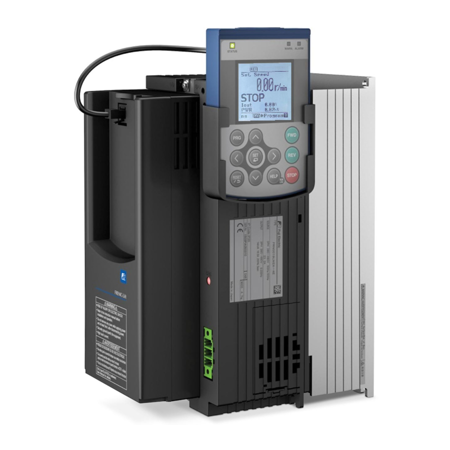
- Page 222 3.1 LCD monitor, keys and LED indicators on the keypad 3.1 LCD monitor, keys and LED indicators on the keypad The keypad “TP-A1-LM2” allows you to run and stop the motor, monitor the running status, specify the function code data, and monitor I/O signal states, maintenance information, and alarm information. LED indicators LCD monitor Programming keys...
- Page 223 Table 3.2 Overview of Keypad Functions Keys Functions This key switches the operation modes between Running mode/Alarm mode and Programming mode. Reset key which works as follows according to the operation modes. In Running mode: This key cancels the screen transition. ...
- Page 224 3.1 LCD monitor, keys and LED indicators on the keypad LCD Monitor The LCD monitor shows various information of the inverter according to the operation modes. < Screen example in Running mode > Status icons Speed 1450 Main monitor Travel direction indicator Running status Sub monitors...
- Page 225 Table 3.3 Icons on the LCD Monitor Status icons that show the running status, run command sources and various icons Running status Running forward (rotation direction) Running reverse Run command source External terminals Communications link Keypad in local mode Password protection state Locked with password 1 (Function code data change is prohibited.) Lock being released (Password being canceled temporally) Travel direction...
- Page 226 3.2 Overview of Operation Modes 3.2 Overview of Operation Modes The keypad has the following three operation modes: Running mode : After powered ON, the inverter automatically enters this mode. This mode allows you to specify the reference speed, and run/stop the motor with the keys during local mode.
- Page 227 3.3 Running Mode When the inverter is turned on, it automatically enters Running mode in which you can: (1) Monitor the running status (e.g., reference speed and output current), (2) Switch between remote and local modes, (3) Configure the reference speed (pre-ramp), and (4) Run/stop the motor.
- Page 228 3.3 Running Mode 3.3.2 Remote and Local modes The inverter is available in either remote or local mode. In remote mode, which applies to normal operation, the inverter is driven under the control of the data setting stored in the inverter. In local mode, which applies to maintenance operation, it is separated from the control system and is driven manually under the control by the keypad.
- Page 229 Table 3.6 Available Speed command sources Symbol Command source Symbol Command source HAND Keypad Multistep Multistep speed command Analog speed command Analog speed command AnlgNR Anlg_R (Not reversible) (Reversible) Via RS485 communications link Via RS-485 communications link RS485 Ch1 RS485 Ch2 (port 1: Keypad port) (port 2: Terminal block) Loader...
- Page 230 3.4 Programming Mode 3.4 Programming Mode Programming mode allows the setting and confirmation of function codes, and monitoring of maintenance-related and input/output (I/O) terminal information, as well as other functions. A menu format is used to enable simple function selection. The menu transition for programming mode is shown below.
- Page 231 Table 3.7 Menus available in Programming mode Main Hierarchy Sub-Menu Principal Functions Menu indicator 0. Quick Setup: Shows only frequently used function codes. — — PRG>0 1. Start-up: Sets functions for initial settings. Language PRG>1>1 Sets language to be displayed on LCD monitor. Allows individual initialization of function codes that Select application PRG>1>2...
- Page 232 3.4 Programming Mode 3.4.1 Quick Setup PRG > 0 Menu number 0, "Quick Setup" shows only those function codes predetermined to have a high usage frequency. Menu number 5, "User Config" can be used to add or delete function codes from the Quick Setup. 3.4.2 Start-up PRG >...
- Page 233 3.4.2.3 Display settings: “Disp Setting” PRG > 1 > 3 > 1 > K15 to PRG > 1 > 3 > 13 > K92 Allows setting the keypad display content and behavior. Follow the settings below to display output frequency, current, torque and other necessary information on the keypad's main monitor and sub-monitors.
- Page 234 3.4 Programming Mode 3.4.3 Function Codes PRG > 2 Function code data settings and changes, including copying and initializing data, can be made via programming mode menu number 2, "Function Code". 3.4.3.1 Setting up function code data: “Data Set” PRG > 2 > 1 This section explains how to set function code data.
- Page 235 3.4.3.2 Checking function code data: “Data Check” PRG > 2 > 2 Function codes and function code data can be checked at the same time. Also, function codes that have been changed from their factory default values are indicate by an asterisk (*). Selecting the function code and pressing key allows you to edit or change the displayed function code data.
- Page 236 3.4 Programming Mode 3.4.3.4 Copying function code data: Data Copy” PRG > 2 > 4 This menu provides “Read”, “Write”, “Verify”, and “Check” operation, enabling the following applications. The keypad can hold three sets of function code data in its internal memory to use for three different inverters.
- Page 237 The example below shows screen transition in the case of “I.Write” operation. “Read”, “Write”, and “Verify” operations are similar. Protection status Model name of stored data S.Spd 1450 S.Spd 1450 S.Spd 1450 S.Spd 1450 r/min r/min r/min r/min PRG>2 PRG>2>4 PRG>2>4>1 Quick Setup Data Set...
- Page 238 3.4 Programming Mode Overwritten protection for copied data It allows protecting function code data stored in keypad for each memory slots. In order to protect data, move to the screen for selecting target memory slot at “Read” operation (PRG > 2 .> 4 > 2), and move cursor to target memory slot that you want to protect. Holding down the key on the keypad for 5 seconds or more in above situation, toggles between protected and un-protected state for each memory slots individually.
- Page 239 Error messages Pressing key or key during each operations cancel the operation, and "Canceled" is shown on the screen, and the operation S.Spd 1450 r/min is terminated forcibly. PRG>2>4>1 0019LM2-4 In the case of “Read” operation, the data stored in the selected Canceled.
- Page 240 3.4 Programming Mode 3.4.3.5 Initialize function code data: “Initialize” PRG > 2 > 5 This returns function code data to the values in the factory default settings or sets function code data for certain application system. Changing the data requires double-key operation (the key and the key or the key and the...
- Page 241 Page Category Code Details Output status Rotating forward Rotating reverse Inverter applies DC voltage to the motor Inverter stops output Ramp status During acceleration During deceleration Const During constant speed <Blank> Stopped Motor type Induction motor (asynchronous motor) PMSM Permanent magnet synchronous motor Selected control mode PG-IM Vector control with PG for IM...
- Page 242 3.4 Programming Mode Figure 3.14 Screen transition for “Op Monitor” (display example) 3-21...
- Page 243 3.4.4.2 Check Status of Input/Output Signal Status: “I/O Check” PRG > 3 > 2 This allows confirmation of the inverter’s digital input/output signal and analog input/output signal. This can be used when confirming operational status during maintenance or on test runs. Table 3.12 Display items in “I/O Check”...
- Page 244 3.4 Programming Mode 3.4.4.3 View Maintenance Information: “Maintenance” PRG > 3 > 3 Displays information needed for inverter maintenance. Table 3.13 Display items in “Maintenance” Page Category Code Details Shows cumulative time inverter’s main power has been on. Reverts to 0 after exceeding 65,535 hours and begins counting up Cumulative run time Time again.
- Page 245 Page Category Code Details Shows the cumulative number of times an error has arisen at RS-485 error RS-485 (communications port 1) and the code for the most recent (Communications port 1) error. Shows the cumulative number of times an error has arisen at RS-485 error RS-485 (communications port 2) and the code for the most recent (Communications port 2)
- Page 246 3.4 Programming Mode Figure 3.16 Screen transition for “Maintenance” (display example) 3.4.4.4 View Unit Information: “Unit Info” PRG > 3 > 4 Shows inverter type, serial number and ROM version. S.Spd 1450 r/min PRG>3>4 Type FRN0019LM2A-4E Serial No. XXXXXXXXXXXXXX ROM Version Main:0300 KP:8000 Unit Info...
- Page 247 3.4.4.5 Check/Set travel direction counter function: “Travel Counter” PRG > 3 > 5 This allows to check and set the travel direction counter (TDC) function. For additional information about TDC function, refer to related Application Note (AN-Lift2-0004v100EN). 3.4.5 Alarm Information: “Alarm Info” PRG >...
- Page 248 3.4 Programming Mode Page Category Symbol Details Output status Rotating forward Rotating reverse Inverter applies DC voltage to the motor Inverter stops output Ramp status During acceleration During deceleration Const During constant speed <Blank> Stopped Motor type Induction motor (asynchronous motor) PMSM Permanent magnet synchronous motor Selected control mode...
- Page 249 Figure 3.18 Screen transition for “Alarm History” (display example) 3.4.6 User Configuration: “User Config” PRG > 5 3.4.6.1 Quick setup PRG > 5 > 1 From programming mode menu number 5, “User Config” function codes can be added to or deleted from the Quick Setup.
- Page 250 3.4 Programming Mode 3.4.7 Tools PRG > 6 3.4.7.1 Monitor Customizable Logic: “CLogic Monitor” PRG > 6 > 1 Customizable logic can be previewed graphically in each function block. Step # S.Spd 1450 r/min block function # PRG>6>1[1/200] Step001:2003 Ancillary information Input value S003 MAX:...
- Page 251 3.5 Alarm Mode If an abnormal condition arises, the protective function is invoked and issues an alarm, then the inverter automatically enters Alarm mode. At the same time, an alarm code appears on the LCD monitor. 3.5.1 Releasing the alarm and switching to Running mode Remove the cause of the alarm and press the key to release the alarm and return to Running mode.
- Page 253 In no event will Fuji Electric Co., Ltd. be liable for any direct or indirect damages resulting from the application of the information in this manual.
- Page 254 URL http://www.fujielectric.com/...
Need help?
Do you have a question about the FRENIC-Lift and is the answer not in the manual?
Questions and answers