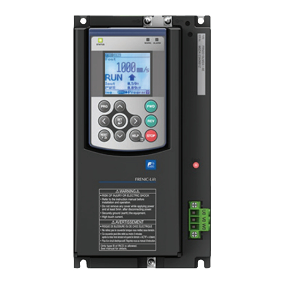
Summary of Contents for Fuji Electric FRENIC-Lift LM2A Series
- Page 1 Starting guide for DCP 3 ph 400 VAC 2.2 – 45 kW 3 ph 200 VAC 4.0 – 15 kW 1 ph 200 VAC 2.2 – 4.0 kW SG_LM2A_DCP_EN_1.0.0...
- Page 2 Version Changes applied Date Written Checked Approved C. Arjona 1.0.0 First version 14.11.2022 J. Alonso J. Català C. Wolf Page 2 of 18 Fuji Electric Europe GmbH...
-
Page 3: Table Of Contents
5.2 DCP 4 (Lift controller with absolute sensor system) ............. 14 6. Signals timing diagram in DCP ................... 15 6.1 DCP 3 (Speed mode) ....................15 6.2 DCP 4 (Remaining distance mode) ................16 7. Travel optimization (Remaining distance mode) ..............17 Page 3 of 18 Fuji Electric Europe GmbH... -
Page 4: Introduction
Firmware version (ROM) can be monitored on TP-E1U in 5_14 and on TP-A1-LM2 in PRG > 3 > 4 For extended information about the product and its use, refer to below mentioned documents: FRENIC-Lift LM2A series Reference Manual INR-SI47-1909_-E (RM). FRENIC-Lift LM2A series Instruction Manual INR-SI47-1894_-E (IM). -
Page 5: Shield Connection
RS485 bus wires. The position of the metal plate depends on the inverter capacity. An example of metal plate position and recommended connection method is shown in figure 1.4. (FRN0011LM2A-7□/ (FRN0039LM2A-4□/ (FRN0060LM2A-4□to FRN0018LM2A-7□) FRN0045LM2A-4□) FRN0091LM2A-4□) (FRN0006LM2A-4□to FRN0032LM2A-4□) Figure 1.4. Metal plate for shield connection position Page 5 of 18 Fuji Electric Europe GmbH... -
Page 6: Terminal Resistor
Move to the previous group which is defined in current page. or − If the previous page is not defined, nothing happens. Back to the original page without storing the function code data. Page 6 of 18 Fuji Electric Europe GmbH... -
Page 7: Remote Display Menus
Remote display is organized by different menus; in each menu different information can be monitored or modified. The name of the menus is listened below: Monitor I/O check Maintenance Alarm Function codes TrqBias Language setting Page 7 of 18 Fuji Electric Europe GmbH... - Page 8 Magnet pole position angle (PP) THETAre 0deg Detected mechanical angle (PS1) THETAm 0000 Magnet binary pole position (PP) 0P/s Incremental signals frequency Z signal (HTL / TTL) 0P/s Figure 2.4. I/O check menu Page 8 of 18 Fuji Electric Europe GmbH...
- Page 9 0.00A VOut 0.0V FRef 0.00Hz Alarm3 Er3 RUN FWD REV IL LV TL Sub 0 Time 646V TempI TempF Term FRE.12345678 * * * Link FRR.12345678FR Out 12345.30ABC Figure 2.6. Alarm menu Page 9 of 18 Fuji Electric Europe GmbH...
-
Page 10: Basic Setting
Cabin suspension (1 for 1:1, 2 for 2:1, 4 for 4:1,…) rated D: Pulley diameter in m i : Gear ratio (in case of gearless = 1) : Motor rated speed (in rpm) at lift maximum speed rated Page 10 of 18 Fuji Electric Europe GmbH... -
Page 11: Lift Speeds
Please note that these parameters have a default setting. Make sure the setting matches with your lift installation, and if not, modify them accordingly. In case the speeds are set to zero, the lift will not move. Page 11 of 18 Fuji Electric Europe GmbH... -
Page 12: Start-Up
Additionally, in parameter W209 PRG > 6 > 3 you can monitor Command byte and Status byte from DCP frame. Table 4.2 shows W209 bit description. Table 4.1. W209 parameter bit description Command byte Status byte Page 12 of 18 Fuji Electric Europe GmbH... -
Page 13: Lift Speed Profile Settings
5.1 DCP 3 (Lift controller without absolute sensor system) Figure 5.1. V4 long travel Figure 5.2. V3 long travel Time (s) Figure 5.3. V2 long travel Time (s) Figure 5.4. Crawl travel Time (s) Figure 5.5. Inspection travel using VI Page 13 of 18 Fuji Electric Europe GmbH... -
Page 14: Dcp 4 (Lift Controller With Absolute Sensor System)
Figure 5.8. Relevelling travel with electric stop 5.2 DCP 4 (Lift controller with absolute sensor system) Time (s) Figure 5.9. V4’ long travel Time (s) Figure 5.10. V3’ long travel Time (s) Figure 5.11. VN’ Relevelling travel Page 14 of 18 Fuji Electric Europe GmbH... -
Page 15: Signals Timing Diagram In Dcp
After zero speed holding time and demagnetization ramp times are finished (H67+L56) the delay time to open main contactors starts (L86). Trip is finished when controller sets to zero B0 bit on command byte. Page 15 of 18 Fuji Electric Europe GmbH... -
Page 16: Dcp 4 (Remaining Distance Mode)
After zero speed holding time and demagnetization ramp times are finished (H67+L56) the delay time to open main contactors starts (L86). Trip is finished when controller sets to zero B0 bit on command byte. Page 16 of 18 Fuji Electric Europe GmbH... -
Page 17: Travel Optimization (Remaining Distance Mode)
L352 value as well. L353 specifies from which speed the early deceleration distance is going to be applied. As default setting is 0.0 %, compensation will be applied for any speed. Page 17 of 18 Fuji Electric Europe GmbH... - Page 18 Swiss Branch Spanish Branch Fuji Electric Europe GmbH, Swiss Branch Fuji Electric Europe GmbH, Sucursal en España Rietlistrasse 5 Carrer dels paletes 8, Edifici B, Primera Planta B 9403 Goldach Parc Tecnològic del Vallès Tel.: +41 71 858 29 49 08290 Cerdanyola (Barcelona) info.swiss@fujielectric-europe.com...


Need help?
Do you have a question about the FRENIC-Lift LM2A Series and is the answer not in the manual?
Questions and answers