Advertisement
Available languages
Available languages
Quick Links
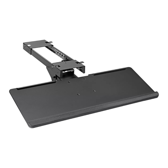
H-10033
UNDER-DESK
KEYBOARD TRAY
TOOLS NEEDED
Drill Bit
Drill
(optional)
Track x 1
M5 x 8 mm Bolt x 8
NOTE: Keyboard tray weight capacity is 4.4 lbs.
NOTE: Keyboard tray can be assembled with
or without brackets, allowing for universal
attachment to a variety of desks.
• If no obstructions are underneath the desktop,
brackets do not need to be installed. Keyboard
tray can be attached flush to the underside of the
desktop.
• If obstructions are underneath the desktop, such
as a desk's support frame, brackets will need to be
installed to make the keyboard tray compatible.
For example, if attaching to Uline's Adjustable Height
Desks, brackets must be installed to the track to
clear the support frame underneath desktop.
PAGE 1 OF 9
1-800-295-5510
uline.com
Two Person Assembly
Phillips
Recommended
Screwdriver
Mount x 1
Wood Screw x 4
ASSEMBLY
PARTS
Keyboard Tray x 1
M5 x 12 mm Bolt x 4
WITHOUT BRACKETS
1. Attach the mount to the track using four
M5 x 8 mm bolts. Tighten using Phillips screwdriver.
(See Figure 1)
Figure 1
Track
Mount
Para Español, vea páginas 4-6.
Pour le français, consulter les pages 7-9.
Bracket x 2
(optional)
Cap x 4
M5 x 8 mm Bolt
0522 IH-10033
Advertisement

Related Manuals for U-Line H-10033


Summary of Contents for U-Line H-10033
- Page 1 Para Español, vea páginas 4-6. Pour le français, consulter les pages 7-9. H-10033 1-800-295-5510 uline.com UNDER-DESK KEYBOARD TRAY TOOLS NEEDED Two Person Assembly Drill Bit Phillips Recommended Drill (optional) Screwdriver PARTS Track x 1 Mount x 1 Keyboard Tray x 1...
- Page 2 ASSEMBLY CONTINUED 2. Attach keyboard tray to mount using four M5 x 12 mm WITH BRACKETS bolts. Tighten using Phillips screwdriver. Insert four With both brackets angled outward, attach brackets caps to cover bolts. (See Figure 2) to track with four M5 x 8 mm bolts. Tighten using Phillips screwdriver.
- Page 3 ASSEMBLY CONTINUED ADJUSTING KEYBOARD TRAY 3. Attach keyboard tray to mount using four M5 x 12 mm bolts. Tighten using Phillips screwdriver. Insert four Loosen bolt on the underside of mount to allow caps to cover bolts. (See Figure 6) keyboard tray to swivel left or right.
-
Page 4: Herramientas Necesarias
H-10033 800-295-5510 uline.mx REPISA PARA TECLADO DEBAJO DE ESCRITORIO HERRAMIENTAS NECESARIAS Se Recomienda Armar Broca Desarmador Entre Dos Personas Taladro (opcional) de Cruz PARTES 1 Riel 1 Base 1 Repisa para Teclado 2 Soportes (opcionales) 8 Pernos M5 x 8 mm... - Page 5 CONTINUACIÓN DEL ENSAMBLE CON SOPORTES Fije la repisa para teclado a la base usando cuatro pernos M5 x 12 mm. Apriete utilizando un desarmador 1. Con ambos soportes en ángulo hacia afuera, fije de cruz. Inserte cuatro tapas para cubrir los pernos. (Vea los soportes al riel con cuatro pernos M5 x 8 mm.
- Page 6 CONTINUACIÓN DEL ENSAMBLE AJUSTE DE LA REPISA PARA TECLADO 3. Fije la repisa para teclado al montaje usando cuatro pernos M5 x 12 mm. Apriete utilizando un Suelte el perno en la parte inferior de la base para desarmador de cruz. Inserte cuatro tapas para cubrir permitir que la repisa para teclado gire hacia la los pernos.
-
Page 7: Outils Requis
H-10033 1-800-295-5510 uline.ca PLATEAU À CLAVIER SOUS BUREAU OUTILS REQUIS Montage à deux Mèche de Tournevis personnes recommandé perceuse cruciforme Perceuse (optionnel) PIÈCES Rail x 1 Dispositif de montage x 1 Plateau à clavier x 1 Support x 2 (optionnel) Boulon M5 x 8 mm x 8 Vis à... - Page 8 MONTAGE SUITE AVEC SUPPORTS 2. Fixez le plateau à clavier au dispositif de montage avec quatre boulons M5 x 12 mm. Serrez le tout en En gardant les deux supports orientés vers l'extérieur, vous servant du tournevis cruciforme. Insérez quatre fixez-les au rail à...
- Page 9 MONTAGE SUITE 3. Fixez le plateau à clavier au dispositif de montage Figure 7 avec quatre boulons M5 x 12 mm. Serrez le tout en Surface de table vous servant du tournevis cruciforme. Insérez quatre capuchons pour couvrir les boulons. (Voir Figure 6) Figure 6 Capuchon Boulon M5 x 12 mm...
Need help?
Do you have a question about the H-10033 and is the answer not in the manual?
Questions and answers