Table of Contents
Advertisement
Quick Links
Owner's Manual & Safety Instructions
Save This Manual
operating, inspection, maintenance and cleaning procedures. Write the product's serial number in the
back of the manual (or month and year of purchase if product has no number). Keep this manual and the
receipt in a safe and dry place for future reference.
Email our technical support at: productsupport@harborfreight.com
When unpacking, make sure that the product is intact
and undamaged. If any parts are missing or broken,
please call 1-888-866-5797 as soon as possible.
©
Copyright
2022 by Harbor Freight Tools
No portion of this manual or any artwork contained herein may be reproduced in
any shape or form without the express written consent of Harbor Freight Tools.
Diagrams within this manual may not be drawn proportionally. Due to continuing
improvements, actual product may differ slightly from the product described herein.
Tools required for assembly and service may not be included.
Keep this manual for the safety warnings and precautions, assembly,
Visit our website at: http://www.harborfreight.com
®
. All rights reserved.
Read this material before using this product.
Failure to do so can result in serious injury.
SAVE THIS MANUAL.
22d
Advertisement
Table of Contents

Subscribe to Our Youtube Channel
Related Manuals for Bauer 21107E-B


Summary of Contents for Bauer 21107E-B
- Page 1 Owner’s Manual & Safety Instructions Save This Manual Keep this manual for the safety warnings and precautions, assembly, operating, inspection, maintenance and cleaning procedures. Write the product’s serial number in the back of the manual (or month and year of purchase if product has no number). Keep this manual and the receipt in a safe and dry place for future reference.
-
Page 2: Important Safety Information
Table of Contents Safety ............2 Maintenance ..........12 Specifications ..........7 Parts List and Diagram ......14 Setup ............7 Warranty ............ 16 Operation ............ 2 WARNING SYMBOLS AND DEFINITIONS This is the safety alert symbol. It is used to alert you to potential personal injury hazards. - Page 3 14. MAINTAIN TOOLS WITH CARE. Keep Table A: RECOMMENDED MINIMUM WIRE GAUGE tools sharp and clean for best and safest FOR EXTENSION CORDS performance. Follow instructions for (120 VOLT) lubricating and changing accessories. EXTENSION CORD NAMEPLATE 15. DISCONNECT TOOLS before servicing; LENGTH AMPERES when changing accessories, such as...
- Page 4 Grounding Instructions TO PREVENT ELECTRIC SHOCK AND DEATH FROM INCORRECT GROUNDING WIRE CONNECTION READ AND FOLLOW THESE INSTRUCTIONS: 110-120 VAC Grounded Tools: Tools with Three Prong Plugs 1. In the event of a malfunction or breakdown, 6. Repair or replace damaged or grounding provides a path of least resistance for worn cord immediately.
-
Page 5: Sander Safety Warnings
Sander Safety Warnings For Your Own Safety Read Instruction 11. Only use safety equipment that has been approved Manual Before Operating Sander by an appropriate standards agency. Unapproved safety equipment may not provide adequate 1. Wear eye protection. protection. Eye protection must be ANSI-approved and breathing protection must be NIOSH-approved 2. -
Page 6: Vibration Safety
Vibration Safety This tool vibrates during use. Repeated or 2. Do not smoke during use. Nicotine reduces long-term exposure to vibration may cause the blood supply to the hands and fingers, temporary or permanent physical injury, increasing the risk of vibration-related injury. particularly to the hands, arms and shoulders. - Page 7 Specifications Electrical Rating 120VAC / 60Hz / 8A Disc Size 12" Maximum Speed 1725 RPM Setup - Before Use: Read the ENTIRE IMPORTANT SAFETY INFORMATION section at the beginning of this manual including all text under subheadings therein before set up or use of this product. TO PREVENT SERIOUS INJURY FROM ACCIDENTAL OPERATION: Turn the Power Switch of the tool off and unplug the tool from its electrical outlet before performing any procedure in this section.
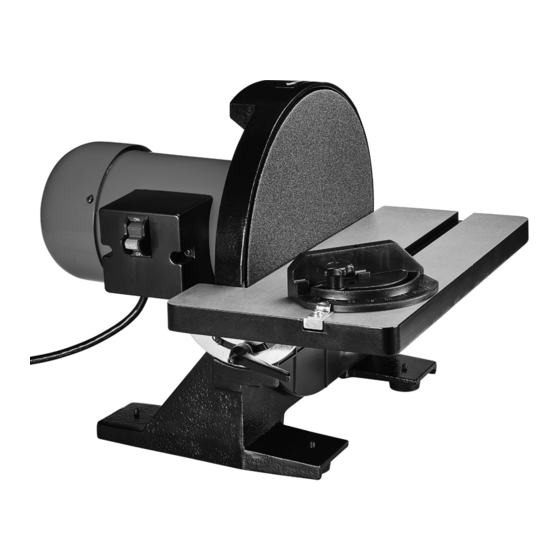
- Page 8 Functions Safety Switch Insert the Safety Key into the Switch. This Key is a safety precaution and should remain in the Switch during use and be removed after Switch is turned off and/or any time the Disc Sander is left unattended or in storage. Motor Sanding Disc...
- Page 9 Operating Instructions Read the ENTIRE IMPORTANT SAFETY INFORMATION section at the beginning of this manual including all text under subheadings therein before set up or use of this product. Tool Set Up TO PREVENT SERIOUS INJURY FROM ACCIDENTAL OPERATION: Turn the Power Switch of the tool off and unplug the tool from its electrical outlet before performing any procedure in this section.
-
Page 10: Workpiece And Work Area Set Up
Workpiece and Work Area Set Up 1. Designate a work area that is clean and well 3. Secure loose workpieces using a vise or clamps lit. The work area must not allow access by (not included) to prevent movement while working. children or pets to prevent distraction and injury. - Page 11 General Operating Instructions 1. Make sure that the Switch is in the off-position, Bevel Sanding then plug in the tool. 1. Loosen the two Locking Handles. 2. Insert Safety Key into Switch. 2. Tilt table to desire angle using the bevel gauge. 3.
-
Page 12: Cleaning, Maintenance, And Lubrication
Maintenance and Servicing Procedures not specifically explained in this manual must be performed only by a qualified technician. TO PREVENT SERIOUS INJURY FROM ACCIDENTAL OPERATION: Turn the Power Switch of the tool off and unplug the tool from its electrical outlet before performing any procedure in this section. -
Page 13: Troubleshooting
Troubleshooting Problem Possible Causes Likely Solutions Disc Sander 1. Not plugged in. 1. Plug in Sander. does not turn on 2. No power at outlet. 2. Check power at outlet and/or circuit breaker. 3. Safety Key not inserted into Switch. 3. -
Page 14: Parts List
Parts List and Diagram PLEASE READ THE FOLLOWING CAREFULLY THE MANUFACTURER AND/OR DISTRIBUTOR HAS PROVIDED THE PARTS LIST AND ASSEMBLY DIAGRAM IN THIS MANUAL AS A REFERENCE TOOL ONLY. NEITHER THE MANUFACTURER OR DISTRIBUTOR MAKES ANY REPRESENTATION OR WARRANTY OF ANY KIND TO THE BUYER THAT HE OR SHE IS QUALIFIED TO MAKE ANY REPAIRS TO THE PRODUCT, OR THAT HE OR SHE IS QUALIFIED TO REPLACE ANY PARTS OF THE PRODUCT. -
Page 15: Assembly Diagram
Assembly Diagram Item 58862 For technical questions, please call 1-888-866-5797. Page 15... - Page 16 Limited 90 Day Warranty Harbor Freight Tools Co. makes every effort to assure that its products meet high quality and durability standards, and warrants to the original purchaser that this product is free from defects in materials and workmanship for the period of 90 days from the date of purchase.
Need help?
Do you have a question about the 21107E-B and is the answer not in the manual?
Questions and answers