Advertisement
Quick Links
Owner's Manual & Safety Instructions
Save This Manual
operating, inspection, maintenance and cleaning procedures. Write the product's serial number in the
back of the manual near the assembly diagram (or month and year of purchase if product has no number).
Keep this manual and the receipt in a safe and dry place for future reference.
Email our technical support at: productsupport@harborfreight.com
When unpacking, make sure that the product is intact
and undamaged. If any parts are missing or broken,
please call 1-888-866-5797 as soon as possible.
©
Copyright
2021 by Harbor Freight Tools
No portion of this manual or any artwork contained herein may be reproduced in
any shape or form without the express written consent of Harbor Freight Tools.
Diagrams within this manual may not be drawn proportionally. Due to continuing
improvements, actual product may differ slightly from the product described herein.
Tools required for assembly and service may not be included.
Keep this manual for the safety warnings and precautions, assembly,
Visit our website at: http://www.harborfreight.com
®
. All rights reserved.
Read this material before using this product.
Failure to do so can result in serious injury.
SAVE THIS MANUAL.
21c
Advertisement

Subscribe to Our Youtube Channel
Related Manuals for Bauer 20106E-B


Summary of Contents for Bauer 20106E-B
- Page 1 Owner’s Manual & Safety Instructions Save This Manual Keep this manual for the safety warnings and precautions, assembly, operating, inspection, maintenance and cleaning procedures. Write the product’s serial number in the back of the manual near the assembly diagram (or month and year of purchase if product has no number). Keep this manual and the receipt in a safe and dry place for future reference.
-
Page 2: Table Of Contents
table of contents Safety ................2 Maintenance .............11 Specifications ............6 Parts List and Diagram ..........14 Setup .................6 Warranty ..............16 Operation ..............8 WarninG SyMBOLS anD DEFinitiOnS This is the safety alert symbol. It is used to alert you to potential personal injury hazards. Obey all safety messages that follow this symbol to avoid possible injury or death. - Page 3 13. DON’T OVERREACH. table a: rEcOMMEnDED MiniMuM WirE GauGE Keep proper footing and balance at all times. FOr EXtEnSiOn cOrDS (120 VOLt) 14. MAINTAIN TOOLS WITH CARE. Keep EXtEnSiOn cOrD tools sharp and clean for best and safest naMEpLatE performance. Follow instructions for LEnGtH aMpErES lubricating and changing accessories.
- Page 4 Grounding instructions tO prEVEnt ELEctric SHOcK anD DEatH FrOM incOrrEct GrOunDinG WirE cOnnEctiOn rEaD anD FOLLOW tHESE inStructiOnS: 110-120 Vac Grounded tools: tools with three prong plugs 1. In the event of a malfunction or breakdown, 6. Repair or replace damaged or grounding provides a path of least resistance for worn cord immediately.
- Page 5 9. DO nOt OpEratE WitH any GuarD 14. Industrial applications must follow OSHA guidelines. DiSaBLED, DaMaGED, Or rEMOVED. Moving 15. Maintain labels and nameplates on the tool. guards must move freely and close instantly. These carry important safety information. 10. The use of accessories or attachments not If unreadable or missing, contact recommended by the manufacturer may Harbor Freight Tools for a replacement.
-
Page 6: Specifications
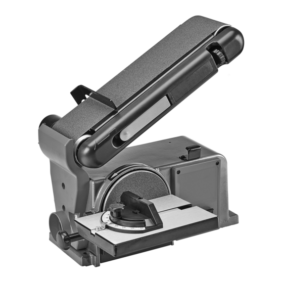
Specifications Electrical Rating Belt Size 4" W x 36" L Disc Size 6" 3565 RPM (Disc) Maximum Speed 1800 FPM (Belt) Setup - Before use: read the EntirE iMpOrtant SaFEty inFOrMatiOn section at the beginning of this manual including all text under subheadings therein before set up or use of this product. tO prEVEnt SEriOuS inJury FrOM acciDEntaL OpEratiOn: turn the power Switch of the tool off and unplug the tool from its electrical outlet before performing any procedure in this section. - Page 7 assembly/Mounting Mounting Sander 1. Select a workbench or mounting location that is 2. Use the mounting bolt holes provided in the Base able to support the weight of the Sander, plus to mount the Sander to the mounting location any additional weight placed on it during use. before use.
-
Page 8: Operation
Operating instructions read the EntirE iMpOrtant SaFEty inFOrMatiOn section at the beginning of this manual including all text under subheadings therein before set up or use of this product. tool Set up tO prEVEnt SEriOuS inJury FrOM acciDEntaL OpEratiOn: turn the power Switch of the tool off and unplug the tool from its electrical outlet before performing any procedure in this section. - Page 9 Belt Support changing Belt Support assembly position assembly The Sanding Belt Support Assembly can be used in a horizontal or vertical position or at any angle in-between. To change the Belt Support position, do the following: 1. Loosen the Belt Support Locking Screw Belt Support Belt Support and raise the Belt Support Assembly to...
- Page 10 Work area Set up 1. Designate a work area that is clean and well 3. Route the power cord along a safe route to reach lit. The work area must not allow access by the work area without creating a tripping hazard or children or pets to prevent distraction and injury.
-
Page 11: Maintenance
Maintenance and Servicing procedures not specifically explained in this manual must be performed only by a qualified technician. tO prEVEnt SEriOuS inJury FrOM acciDEntaL OpEratiOn: turn the power Switch of the tool off and unplug the tool from its electrical outlet before performing any procedure in this section. - Page 12 Sanding Belt replacement 1. Loosen the Belt Support Locking Screw. Drum Raise the Belt Support Assembly to 45° and tighten the Locking Screw. 2. Pull the Belt Tension Lever out to release Belt tension on the Sanding Belt. Support assembly 3.
- Page 13 troubleshooting problem possible causes Likely Solutions Belt/Disc Sander 1. Not plugged in. 1. Plug in Sander. does not turn on 2. No power at outlet. 2. Check power at outlet and/or circuit breaker. 3. Safety Key not inserted into Switch. 3.
-
Page 14: Parts List And Diagram
parts List and Diagram parts List part Description part Description Screw Power Cord Base Plate Hex Socket Screw M8 30 Screw Hex Bolt M6 20 Star Washer Sanding Belt Screw St4.2 10 Set Screw M8 16/Washer Disc Guard Bracket Sanding Disc Screw M5 16 Hex Socket Screw Bearing Housing... - Page 15 assembly Diagram Item 58339 For technical questions, please call 1-888-866-5797. Page 15...
-
Page 16: Warranty
pLEaSE rEaD tHE FOLLOWinG carEFuLLy THE MANUFACTURER AND/OR DISTRIBUTOR HAS PROVIDED THE PARTS LIST AND ASSEMBLY DIAGRAM IN THIS MANUAL AS A REFERENCE TOOL ONLY. NEITHER THE MANUFACTURER OR DISTRIBUTOR MAKES ANY REPRESENTATION OR WARRANTY OF ANY KIND TO THE BUYER THAT HE OR SHE IS QUALIFIED TO MAKE ANY REPAIRS TO THE PRODUCT, OR THAT HE OR SHE IS QUALIFIED TO REPLACE ANY PARTS OF THE PRODUCT.
Need help?
Do you have a question about the 20106E-B and is the answer not in the manual?
Questions and answers