Table of Contents
Advertisement
Quick Links
ES/EM 14
//
Montage- und Anschlussanleitung / Positionsschalter
Mounting and wiring instructions / Position switch
Instructions de montage et de câblage / Interrupteur de position
Istruzioni di montaggio e collegamento / Interruttore di posizione
Instruções de montagem e instalação / Chave fim de curso
Инструкция по монтажу и подключению / Позиционный выключатель
Deutsch (Originalbetriebsanleitung)
Nutzung der Montage- und Anschlussanleitung
Zielgruppe: autorisiertes Fachpersonal.
Sämtliche in dieser Montageanleitung beschriebenen Handhabungen
dürfen nur durch ausgebildetes und vom Anlagenbetreiber autorisier-
tes Fachpersonal durchgeführt werden.
1. Montage- und Anschlussanleitung lesen und verstehen.
2. Geltende Vorschriften über Arbeitssicherheit und Unfallverhütung
einhalten.
3. Gerät installieren und in Betrieb nehmen.
Auswahl und Einbau der Geräte sowie ihre steuerungstechnische Ein-
bindung sind an eine qualifizierte Kenntnis der einschlägigen Gesetze
und normativen Anforderungen durch den
Maschinenhersteller geknüpft.
Im Zweifelsfall ist die deutsche Sprachversion dieser
Anleitung maßgeblich.
Lieferumfang
1 Gerät, 1 Montage- und Anschlussanleitung, Kartonage.
Bestimmungsgemäßer Gebrauch
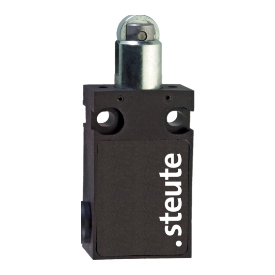
Das Gerät dient dem Einsatz in Sicherheitsstromkreisen zur Stel-
lungsüberwachung beweglicher Schutzeinrichtungen nach EN ISO
14119 (EN 1088) Bauart 1 und EN 60947-5-1.
Befestigung und Anschluss
Das Gerät auf einer ebenen Fläche befestigen. Bei der Montage darauf
achten, dass ein Verschieben des Geräts nicht möglich ist. Dies gilt
auch im Fehlerfall. Das Gerät gegen unbefugte Manipulation sichern,
z.B. mit Einweg-Sicherheitsschrauben. Sie sind optional erhältlich. Bei
der Montage des Geräts die Anforderungen nach EN 14119, insbeson-
dere die Punkte 5.1 bis 5.4, berücksichtigen! Beachten Sie die Hinwei-
se der Normen EN ISO 12100 und EN ISO 14120.
Hinweise
Der elektrische Anschluss darf nur von autorisiertem Fachpersonal
durchgeführt werden. Das Gerät nicht als mechanischen Anschlag
verwenden. Die Gebrauchslage ist beliebig. Umbauten und Verände-
rungen am Gerät sind nicht gestattet. Die hier beschriebenen Produk-
te wurden entwickelt, um als Teil einer Gesamtanlage oder Maschine
sicherheitsgerichtete Funktionen zu übernehmen. Ein komplettes si-
cherheitsgerichtetes System enthält in der Regel Sensoren, Auswerte-
einheiten, Meldegeräte und Konzepte für sichere Abschaltungen. Hier-
zu ist auch eine Validierung nach EN ISO 13849-2 bzw. nach EN 62061
erforderlich. Desweiteren kann der Performance-Level nach EN ISO
13849-1 bzw. SIL-CL-Level nach EN 62061 durch Verkettung von
mehreren Sicherheitsbauteilen und anderen sicherheitsgerichteten
Geräten, z.B. Reihenschaltung von Sensoren, niedriger ausfallen als
die Einzellevel. Es liegt im Verantwortungsbereich des Herstellers
einer Anlage oder Maschine, die korrekte Gesamtfunktion sicherzu-
stellen. Technische Änderungen vorbehalten.
Wartung
Bei rauen Betriebsbedingungen empfehlen wir eine regelmäßige
Wartung mit folgenden Schritten:
1. Betätiger auf Leichtgängigkeit prüfen.
2. Schmutz entfernen.
3. Prüfen der Leitungseinführung und -anschlüsse.
Reinigung
- Bei feuchter Reinigung: Wasser oder milde, nicht-scheuernde,
nicht-kratzende Reinigungsmittel verwenden.
- Keine aggressiven Reinigungsmittel oder Lösungsmittel verwenden.
Entsorgung
- Nationale, lokale und gesetzliche Bestimmungen zur
Entsorgung beachten.
- Materialien getrennt dem Recycling zuführen.
English
Use of the mounting and wiring instructions
Target group: authorised and qualified staff.
All actions described in these instructions may only be performed by
qualified persons who have been trained and authorised by the
operating company.
1. Read and understand these mounting and wiring instructions.
2. Comply with the valid occupational safety and accident prevention
regulations.
3. Install and operate the device.
Selection and installation of devices and their integration in control
systems demand qualified knowledge of all the relevant laws, as well
as the normative requirements of the machine manufacturer.
In case of doubt, the German language version of these instructions
shall prevail.
Scope of delivery
1 device, 1 mounting and wiring instructions, carton.
Intended use
The device is used in safety circuits to monitor the position of mobile
safety guards to EN ISO 14119 (EN 1088) type 1 and EN 60947-5-1.
Mounting and wiring
Mount the device on an even surface. Ensure that the device cannot
be moved from its position. Ensure this in case of failure, too. For
protection against unauthorized manipulation, use e.g. one way safe-
ty screws. They are optionally available. When mounting the device,
observe the requirements of EN 14119, especially the sections 5.1 to
5.4! Observe the instructions in the standards EN ISO 12100 and
EN ISO 14120.
1 / 12
Advertisement
Table of Contents

Related Manuals for steute ES 14


Summary of Contents for steute ES 14
- Page 1 ES/EM 14 Montage- und Anschlussanleitung / Positionsschalter Mounting and wiring instructions / Position switch Instructions de montage et de câblage / Interrupteur de position Istruzioni di montaggio e collegamento / Interruttore di posizione Instruções de montagem e instalação / Chave fim de curso Инструкция...
-
Page 2: Maintenance
ES/EM 14 Montage- und Anschlussanleitung / Positionsschalter Mounting and wiring instructions / Position switch Instructions de montage et de câblage / Interrupteur de position Istruzioni di montaggio e collegamento / Interruttore di posizione Instruções de montagem e instalação / Chave fim de curso Инструкция... -
Page 3: Manutenzione
ES/EM 14 Montage- und Anschlussanleitung / Positionsschalter Mounting and wiring instructions / Position switch Instructions de montage et de câblage / Interrupteur de position Istruzioni di montaggio e collegamento / Interruttore di posizione Instruções de montagem e instalação / Chave fim de curso Инструкция... - Page 4 ES/EM 14 Montage- und Anschlussanleitung / Positionsschalter Mounting and wiring instructions / Position switch Instructions de montage et de câblage / Interrupteur de position Istruzioni di montaggio e collegamento / Interruttore di posizione Instruções de montagem e instalação / Chave fim de curso Инструкция...
- Page 5 - Соблюдать национальные, локальные и нормативные требования Contatos по утилизации. Контакты - Материалы отдавать в утилизацию раздельно. ES 14 1Ö/1S Abmessungen Dimensions Dimensions ES 14 1Ö/1S UL/CSA Dimensioni Dimensões Габариты ES 14 2Ö/1S ES/EM 14 ES 14 2Ö ES 14 2Ö UL/CSA EM 14 1Ö/1S...
- Page 6 ES/EM 14 Montage- und Anschlussanleitung / Positionsschalter Mounting and wiring instructions / Position switch Instructions de montage et de câblage / Interrupteur de position Istruzioni di montaggio e collegamento / Interruttore di posizione Instruções de montagem e instalação / Chave fim de curso Инструкция...
- Page 7 Anschlussart 2-, 3-, 4- oder 6-adrige Anschlussleitung Disponível com os seguintes atuadores. Anschlussquerschnitt ES 14 1Ö/1S, 2Ö: 4 x 0,75 mm² oder AWG 20 Поставляется со следующими приводами ES 14 2Ö/1S: 6 x 0,56 mm² oder AWG 20 EM 14: 3 x 0,75 mm² oder AWG 20 EM 14 1Ö/1S: 4 x 0,75 mm²...
-
Page 8: Données Techniques
2-, 3-, 4-, or 6-wire cable EM 14: 5 A/250 VAC; 0,16 A/230 VDC Cable cross-section ES 14 1Ö/1S, 2Ö: 4 x 0.75 mm² or AWG 20 Catégorie d’utilisation AC-15; DC-13 ES 14 2Ö/1S: 6 x 0.56 mm² or AWG 20 Protection contre les EM 14: 3 x 0.75 mm²... -
Page 9: Технические Данные
2, 3, 4 ou 6 vias ной нагрузки) 2 миллиона Seção máx. cabo ES 14 1Ö/1S, 2Ö: 4 x 0,75 mm² ou AWG 20 макс. 20 лет ES 14 2Ö/1S: 6 x 0,56 mm² ou AWG 20 4 kV EM 14: 3 x 0,75 mm²... -
Page 10: Eu-Konformitätserklärung Eu Declaration Of Conformity
Löhne, 27. Januar 2022 / 27 January, 2022 Rechtsverbindliche Unterschrift, Ort und Datum der Ausstellung Place and date of issue Marc Stanesby (Geschäftsführer) Legally binding signature, Marc Stanesby (Managing Director) steute Technologies GmbH & Co KG, Brückenstr. 91, 32584 Löhne, Germany 10 / 12... - Page 11 Löhne, 15. September 2021 / 15 September, 2021 Rechtsverbindliche Unterschrift, Ort und Datum der Ausstellung Place and date of issue Marc Stanesby (Geschäftsführer) Legally binding signature, Marc Stanesby (Managing Director) steute Technologies GmbH & Co KG, Brückenstr. 91, 32584 Löhne, Germany 11 / 12...
- Page 12 Zusatzinformation zu Montage- und Anschlussanleitungen Additional information on mounting and wiring instructions Information complémentaire aux instructions de montage et de câblage Ulteriori informazioni sulle istruzioni di collegamento e montaggio Informação adicional para as instruções de montagem Дополнительная информация по монтажу и инструкциям по подключению [bg] При...
Need help?
Do you have a question about the ES 14 and is the answer not in the manual?
Questions and answers