Table of Contents
Advertisement
Quick Links
LINEAR & ROTARY ACTUATOR
INSTALLATION, OPERATION AND SERVICE
MANUAL
Information furnished by EXLAR Corporation is believed to be accurate and reliable. However, no responsibility is assumed by
EXLAR Corporation for its use. EXLAR reserves the right to change the design and operation of the equipment described herein
and any associated motion products that may appear in this document. Information in this document pertaining to equipment not
furnished by EXLAR should be confirmed by that equipment manufacturer. EXLAR assumes no responsibility for changes to
information by other manufacturers or errors in that information or the description of that information. Information in this document is
subject to change without notice.
1
Tritex 1 Installation and Setup
09/27/12
PN: 27666
Exlar Corporation
Rev. M
952-500-6200M
Advertisement
Table of Contents
Troubleshooting

Related Manuals for Exlar Tritex


Summary of Contents for Exlar Tritex
- Page 1 Information furnished by EXLAR Corporation is believed to be accurate and reliable. However, no responsibility is assumed by EXLAR Corporation for its use. EXLAR reserves the right to change the design and operation of the equipment described herein and any associated motion products that may appear in this document. Information in this document pertaining to equipment not furnished by EXLAR should be confirmed by that equipment manufacturer.
- Page 2 Terms and Conditions above), provided, however, that written notice of claimed defects shall have been given to Exlar within thirty (30) days from the date of any such defect is first discovered. The product(s) claimed to be defective must be returned to Exlar, transportation prepaid by Buyer, with written specification of the claimed defect.
- Page 3 Exlar. Seller's maximum liability with respect to these terms and conditions and any resulting...
- Page 4 None of the functions or features of the Tritex actuator may be used to ensure safety of personnel, i.e. they must not be used for safety-related functions. Careful consideration must be given to the functions of the actuator which might result in a hazard, either through their intended behavior or through incorrect operation due to a fault.
-
Page 5: Table Of Contents
Table of Contents TRITEX™ PRODUCT OVERVIEW ................. 9 General Specifications ........................11 Drive specifications for TRA500 remote option ..................11 Specifications: Size 20 Linear Actuators.................... 12 TLM20 ............................... 12 TSM20............................... 13 Specifications: Size 30 Linear Actuators.................... 14 TLM30 ............................... 14 TSM30............................... - Page 6 Power Supply Wiring Diagrams ......................42 Power Supply Wiring and Fusing ....................... 43 Power Supply Connections ........................ 44 Tritex Input and Output Wiring ......................45 I/O Power Supply ..........................47 Two Power Supply Configuration ....................... 47 Single Power Supply Configuration ....................47 Digital Inputs ............................
- Page 7 ONLINE DIAGNOSTICS ..................... 101 Tuning ..............................101 Additional Tuning Parameters ......................102 Status, Faults & Warnings......................... 103 Status Display..........................103 Faults, Possible Causes and Solutions .................... 104 Tritex 1 Installation and Setup 09/27/12 PN: 27666 Exlar Corporation Rev. M 952-500-6200M...
- Page 8 Model TTUSB485 USN to 485 Introduction ..................126 Shunt Regulator..........................129 TTSR1 Shunt Regulator Option ....................... 129 EFT/B & Surge Filter .......................... 133 Declaration of Conformity ......................... 134 Tritex 1 Installation and Setup 09/27/12 PN: 27666 Exlar Corporation Rev. M...
-
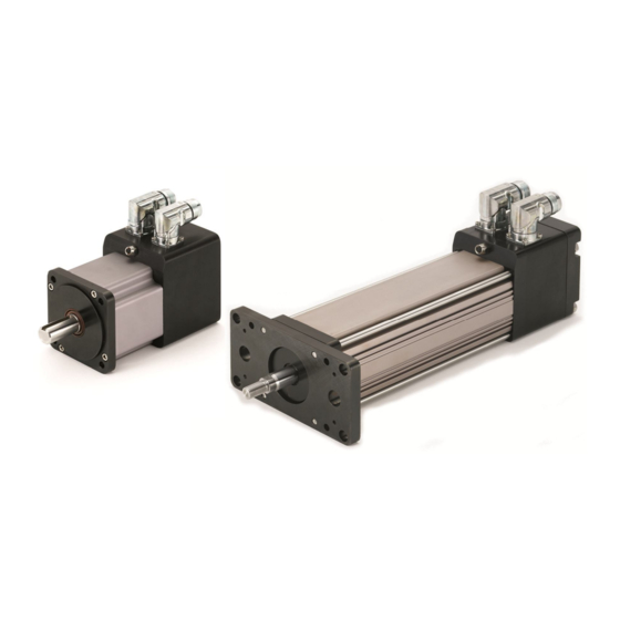
Page 9: Tritex™ Product Overview
Tritex™ Product Overview The Exlar Tritex Series of electric actuators combines an integrated brushless servo motor, amplifier and motion controller. Optionally the system can be configured for remote mounting of the amplifier and motion control 8 inputs 24 – 48V... - Page 10 The Tritex actuators are available in linear and rotary versions with integrated or remote amplifier and motion control. The Remote amplifier and motion control models would typically be used in application where space at the actuator is limited or in applications with high ambient temperatures.
-
Page 11: General Specifications
General Specifications Drive Specification for all Tritex Models with embedded drives Embedded Drive Specifications Input Voltage, Bus 24-48 Volts DC nominal, 20 -60 Volts continuous operating range. and Logic Under voltage trip 19V, Over voltage trip 85V I/O Power Supply... -
Page 12: Specifications: Size 20 Linear Actuators
+/- 0.005 revolutions x lead Stroke Length in (mm) 3 (75) 6 (150) 10 (254) 12 (300) Approximate Weight lb (kg) 7 (3.2) 8.5 (3.9) 10 (4.5) 11.5 (5.2) Tritex 1 Installation and Setup 09/27/12 PN: 27666 Exlar Corporation Rev. M 952-500-6200M... -
Page 13: Tsm20
+/- 0.005 revolutions x lead Stroke Length in (mm) 3 (75) 6 (150) 10 (254) 12 (300) Approximate Weight lb (kg) 6.5 (2.9) 7.0 (3.2) 7.5 (3.4) 8.0 (3.6) Tritex 1 Installation and Setup 09/27/12 PN: 27666 Exlar Corporation Rev. M 952-500-6200M... -
Page 14: Specifications: Size 30 Linear Actuators
Stroke Length in (mm) 3 (75) 6 (150) 10 (254) 12 (300) 18 (450) Approximate Weight lb (kg) 10 (4.5) 12 (5.4) 19.5 (8.8) 21 (9.5) 25.5 (11.6) Tritex 1 Installation and Setup 09/27/12 PN: 27666 Exlar Corporation Rev. M 952-500-6200M... -
Page 15: Tsm30
Stroke Length in (mm) 3 (75) 6 (150) 10 (254) 12 (300) 18 (450) Approximate Weight lb (kg) 9.5 (4.3) 11.5 (5.2) 19 (8.6) 22 (10) 25 (11.3) Tritex 1 Installation and Setup 09/27/12 PN: 27666 Exlar Corporation Rev. M 952-500-6200M... -
Page 16: Specifications: Size 60 Motors And Gear Motors
0.000237 (0.268) 0.000413 (0.466) 0.000589 (0.665) Gearmotor Armature Inertia* lb-in-sec kg-cm 0.000226 (0.255) 0.000401 (0.453) 0.000576 (0.651) *Add armature inertia to gearing inertia for total inertia. Tritex 1 Installation and Setup 09/27/12 PN: 27666 Exlar Corporation Rev. M 952-500-6200M... - Page 17 Gear Stages Lbf-in-sec (kg-cm (0.0149) (0.0137) 0.0000132 16:1 0.0000121 (0.00984) (0.00906) 0.0000087 20:1, 25:1 0.0000080 10:1 0.0000023 (0.00261) 40:1, 50:1, 100:1 0.0000021 (0.00242) SIZE 60 BACKLASH AND EFFICIENCY Tritex 1 Installation and Setup 09/27/12 PN: 27666 Exlar Corporation Rev. M 952-500-6200M...
-
Page 18: Specifications: Size 90 Motors And Gear Motors
0.00054 (0.609) 0.00097 (1.09) 0.00140 (1.58) Gearmotor Armature Inertia* lb-in-sec kg-cm 0.00114 (1.29) 0.00157 (1.77) 0.00200 (2.26) *Add armature inertia to gearing inertia for total inertia. Tritex 1 Installation and Setup 09/27/12 PN: 27666 Exlar Corporation Rev. M 952-500-6200M... - Page 19 SIZE 90 RADIAL LOAD AND BEARING LIFE SIZE 90 MECHANICAL RATINGS SIZE 90 GEARING REFLECTED INERTIA SIZE 90 BACKLASH AND EFFICIENCY Tritex 1 Installation and Setup 09/27/12 PN: 27666 Exlar Corporation Rev. M 952-500-6200M...
-
Page 20: Model Mask And Ordering Information
L1/2/3 = External Limit E = Connections AR = External Anti-rotate Switches RB = Rear Brake I = Exlar std M23 style connector PF = Preloaded Follower* (future option) Bxx = Embedded leads, 3 ft. XT = Special Travel Options Pxx = Embedded leads w/plug, std M23 style connector, 3 ft. - Page 21 REMOTE TRITEX TSM SERIES ORDERING GUIDE AAABB-CCDD-EFG-HHH-HH - (XX…XX - #####) AAA = Actuator Type G = Rod End TSM = Tritex Linear Actuator Used with TRA500 remote drive M = Male US Std Thread A = Male Metric BB = Actuator Frame Size...
- Page 22 REMOTE TRITEX RSM/RSG SERIES ORDERING GUIDE AAABBB-CCC-DE-FFF-FF- (XX…XX) - ##### AAA = Actuator Type E = Connector Options RSM = Tritex Rotary Motor Used with TRA500 remote drive I = Exlar Std M23 style connector RSG = Tritex Rotary Gearmotor Used with TRA500 remote drive...
- Page 23 TRA500 REMOTE TRITEX DRIVE ORDERING GUIDE AAABBB-C - ##### AAA = Drive Type BBB = Power 500 = 500 Watts C = Connector Options N = ½ inch NPT Threaded Holes G = PG Threaded Holes I = Exlar Std M23 style connector...
-
Page 24: Installation
Lubrication The TLM and TSM Series actuators are shipped from the factory fully greased and ready for installation. Exlar recommends using Mobilith SHC 220, a high performance, extreme-pressure grease. The unique physical properties of the synthetic base oil provide outstanding protection against wear, rust, corrosion and high or low-temperature degradation. -
Page 25: General Operation
General Operation The Tritex Series of actuators and motors function in the same manner as a brushless servomotor. The servo amplifier is used to rotate the motor at controlled speed and torque, and for controlled numbers of revolutions and move times. This rotary motion is translated into linear motion by the internal planetary roller screw mechanism of the TLM Series linear actuator. -
Page 26: Tlm/Tsm Anti-Rotate
TLM/TSM Anti-Rotate TLM/TSM20 with Anti-rotate TLM/TSM 30with Anti-rotate Tritex 1 Installation and Setup 09/27/12 PN: 27666 Exlar Corporation Rev. M 952-500-6200M... -
Page 27: Tlm20 Dimensions
TLM20 Dimensions Tritex 1 Installation and Setup 09/27/12 PN: 27666 Exlar Corporation Rev. M 952-500-6200M... -
Page 28: Tsm20 Dimensions
TSM20 Dimensions Tritex 1 Installation and Setup 09/27/12 PN: 27666 Exlar Corporation Rev. M 952-500-6200M... -
Page 29: Tlm30 Dimensions
TLM30 Dimensions Tritex 1 Installation and Setup 09/27/12 PN: 27666 Exlar Corporation Rev. M 952-500-6200M... -
Page 30: Tsm30 Dimensions
TSM30 Dimensions Tritex 1 Installation and Setup 09/27/12 PN: 27666 Exlar Corporation Rev. M 952-500-6200M... -
Page 31: Rtm060 And Rtg060 Dimensions
RTM060 and RTG060 Dimensions RTM060 RTG060 Tritex 1 Installation and Setup 09/27/12 PN: 27666 Exlar Corporation Rev. M 952-500-6200M... -
Page 32: Rsm060 And Rsg060 Dimensions
8.601 [218] 9.851 [250] 1 Stack Stator 2 Stack Stator 3 Stack Stator 2 Stage Gearhead 2 Stage Gearhead 2 Stage Gearhead 8.396 [213] 9.646 [245] 10.896 [277] Tritex 1 Installation and Setup 09/27/12 PN: 27666 Exlar Corporation Rev. M 952-500-6200M... -
Page 33: Rtm090 & Rtg090 Dimensions
RTM090 & RTG090 Dimensions Tritex 1 Installation and Setup 09/27/12 PN: 27666 Exlar Corporation Rev. M 952-500-6200M... -
Page 34: Rsm090 & Rsg090 Dimensions
9.074 [230] 10.074 [256] 1 Stack Stator 2 Stack Stator 3 Stack Stator 2 Stage Gearhead 2 Stage Gearhead 2 Stage Gearhead 9.339 [237] 10.339 [263] 11.339 [288] Tritex 1 Installation and Setup 09/27/12 PN: 27666 Exlar Corporation Rev. M 952-500-6200M... - Page 35 TRA500 Dimensions TRA500 - I TRA500 –N-G-E,-P Tritex 1 Installation and Setup 09/27/12 PN: 27666 Exlar Corporation Rev. M 952-500-6200M...
- Page 36 I/O and communications cables as much as possible. Where power and signal cable proximity is required keep their parallel run distance to a minimum and cross cables at right angles. Tritex 1 Installation and Setup 09/27/12 PN: 27666 Exlar Corporation Rev.
-
Page 37: Tritex Configurations
TLM 30 with M23 connectors, Connector Option I The Models TSM, RSM & RSG are designed to be used with the remote Tritex drive and motion controller, model TRA500, the two are connected via a 1 or 2 meter cable. The TRA500 always comes with an M23 connection to the actuator. - Page 38 B option (Embedded leads) provides a cable with factory connections inside the drive with an IP 65 cable gland and flying leads P option is an provides extension cables with M23 connectors Tritex 1 Installation and Setup 09/27/12 PN: 27666 Exlar Corporation Rev. M...
-
Page 39: Electrical Installation
RS-485 Power Supply Selection The Tritex actuator requires DC power. The actuator Bus and Logic supplies will operate on voltages of 24 or 48 V DC nominal. The continuous operating range is 20-60 VDC. The drive has internal Bus over-voltage fault that will occur at 85VDC. The input current requirements are dependent on the actuator power required for the installation. -
Page 40: Regulated Vs Unregulated Power Supplies
If a regulated power supply is used for bus power, a blocking diode should be installed to protect the power supply. See Power Supply Wiring Diagrams section below Tritex 1 Installation and Setup 09/27/12 PN: 27666 Exlar Corporation Rev. -
Page 41: Grounding
Single point GND Fuse (bonded to enclosure) Actuator Ground & Power Cable Shield DC Supply 24/48 V Power/Logic I/O Power Supply 24 V Other Equipment GND Grounding Diagram Tritex 1 Installation and Setup 09/27/12 PN: 27666 Exlar Corporation Rev. M 952-500-6200M... -
Page 42: Power Supply Wiring Diagrams
Un-Regulated Power Supply for Logic and Bus power, with a shunt regulator CAUTION Reversing polarity of the Bus Power (+) and Power Common (-) will cause a short circuit, which must be protected by the input fuse. See fusing below Tritex 1 Installation and Setup 09/27/12 PN: 27666 Exlar Corporation Rev. -
Page 43: Power Supply Wiring And Fusing
WARNING If the wire gauge for bus power is reduced the fuse Amp rating must also be reduced in accordance with wire size, type and local regulations. Tritex 1 Installation and Setup 09/27/12 PN: 27666 Exlar Corporation Rev. -
Page 44: Power Supply Connections
Terminal Minimum Wire Label for Nor G Bus Power (+) 24-48 VDC Bus + Logic Power (+) 24 -48VDC LOGIC + Power Common (-) COMMON PE (GND) Tritex 1 Installation and Setup 09/27/12 PN: 27666 Exlar Corporation Rev. M 952-500-6200M... -
Page 45: Tritex Input And Output Wiring
Tritex Input and Output Wiring Input/Output Connections 19 pin I/O connector for I or P connector options. Front view “I” or “B” Pin for “I” or “P” Wire Color code TTICP cable connector option connector and “B” connector option FUNCTION... - Page 46 OUT + w/orange) ANALOG orange (pair beige INPUT 8 OUT - w/blue) green (pair Shield drain w/white) ANALOG IN+ white (pair Shield drain ANALOG IN- w/green) Tritex 1 Installation and Setup 09/27/12 PN: 27666 Exlar Corporation Rev. M 952-500-6200M...
-
Page 47: I/O Power Supply
Bus Power V DC Regulated AC Input 200 V, if required Power Power Supply Connector Power Common Field I/O Common Field I/O Power Connector Single Power Supply Configuration Tritex 1 Installation and Setup 09/27/12 PN: 27666 Exlar Corporation Rev. M 952-500-6200M... -
Page 48: Digital Inputs
Digital Inputs The Tritex series product has 8 optically isolated digital inputs. These inputs are sourcing only, they require a positive voltage to turn on. Each input can be assigned to any of the internal input functions (see software section). -
Page 49: Digital Outputs
Digital Outputs The Tritex series product has 4 optically isolated digital outputs. These outputs are sourcing only, they provide a positive voltage when on. Each output can be assigned to any of the internal output functions (see software section). CAUTION Each output is rated to continuously drive a 50 mA load and is short protected at 250 mA with re-settable fuse. -
Page 50: Analog Input
Note: Analog input reference from an external controller must be referenced to single point ground to prevent damage to the analog input circuit. Analog in + 20kΩ Current Mode Selector 500Ω 20kΩ Analog in - Internal Analog Input Circuit Tritex 1 Installation and Setup 09/27/12 PN: 27666 Exlar Corporation Rev. M 952-500-6200M... -
Page 51: Analog Output
Analog Ref Analog output Analog Current Output Specifications Description Specification Current Output Range 0 - 22 mA Load Range 100 to 500 Ω Output resolution 11 bits Tritex 1 Installation and Setup 09/27/12 PN: 27666 Exlar Corporation Rev. M 952-500-6200M... -
Page 52: Communications
Function number TTCOM 485+ Brown 485- Blue 485 COM Black Shield Drain +3.3v 22kΩ RS485 + 10kΩ RS485 - 22kΩ SP3072EE RS485 REF Internal RS 485 Circuit Tritex 1 Installation and Setup 09/27/12 PN: 27666 Exlar Corporation Rev. M 952-500-6200M... -
Page 53: Pc Communications
PE Converter RS485 - 485A (-) Brown 485 B(+) RS485 + RS485 REF Black B&B Electronics TTCOM-xxx USOTL4 Exlar Cable Connection to B&B USOTL4 using TTCOM cable Tritex 1 Installation and Setup 09/27/12 PN: 27666 Exlar Corporation Rev. M 952-500-6200M... -
Page 54: Emc Considerations
EMC Considerations Tritex actuators are designed not to create or be affected by electromagnetic interference in most applications. Under extreme conditions there may be unwanted electromagnetic interaction between the Tritex actuator and other equipment. It is the responsibility of the installer to ensure that the complete system meets all relevant EMC (electromagnetic compatibility) emission and immunity requirements. - Page 55 Tritex Enclosure and Power Supply Enclosure I/O Devices Connect RS485 Cable Shield to Connect I/O Tritex Enclosure Cable Shield to Tritex Enclosure Tritex Actuator Cable Shield Grounding Example Tritex 1 Installation and Setup 09/27/12 PN: 27666 Exlar Corporation Rev. M 952-500-6200M...
-
Page 56: Expert Software
Overview The Expert software is designed to allow customized views of the Tritex drive features for various industries and applications. For example a valve application may use different motion features than a clamping application. The concept of different views is intended to simplify and customize the operation by only showing the parameters needed for the specific application and also allow industry specific names for the drive parameters. -
Page 57: Opening The Expert Software
Opening the Expert Software Welcome Screen When the Expert software is opened the Welcome Screen will be displayed. This screen helps users who are unfamiliar with software get started quickly. Tritex 1 Installation and Setup 09/27/12 PN: 27666 Exlar Corporation Rev. -
Page 58: Quick Connect
Create an Application from a Standard Template Provides a list of canned applications. The page list has already been created for each these applications for specific drive types with drive existing drive file. Select the ApplicationTemplate then click OK. Tritex 1 Installation and Setup 09/27/12 PN: 27666 Exlar Corporation Rev. -
Page 59: Create A New User Application
View / Pages from the main menu bar. The New Application builder displays pages from a default directory. The find Page button can be add pages from other directories into the application. Tritex 1 Installation and Setup 09/27/12 PN: 27666 Exlar Corporation Rev. -
Page 60: Other Welcome Screen Controls
For experienced users this can save a few clicks. For more information, click the in the upper right corner of the dialog box for context sensitive help and then click on the desired field. Tritex 1 Installation and Setup 09/27/12 PN: 27666 Exlar Corporation Rev. -
Page 61: Operation With An Open Application
The Application will most likely have more pages available than initially appear on the tabs, to view other pages click the Page icon or click View / Pages from the main menu and select the page to be viewed. Tritex 1 Installation and Setup 09/27/12 PN: 27666 Exlar Corporation Rev. -
Page 62: Viewing Pages Not In The Application
Application should be saved by selecting File/Save/Application As… Pages may also be added, deleted or selected as hidden by viewing the Application Properties window, select File/Application Properties and then select the Pages tab. Tritex 1 Installation and Setup 09/27/12 PN: 27666 Exlar Corporation Rev. -
Page 63: Basic Steps For Offline Operation
MillimetersPerSecond. Enter the text to displayed such as rpm, ips In/sec etc. For Acceleration select the working units such as InchesPerSecondPerSecond, RevsPerMinutePerSecond, etc. Enter the text to be displayed such as in/sec^2 or rpm/sec. Tritex 1 Installation and Setup 09/27/12 PN: 27666 Exlar Corporation Rev. - Page 64 Cycles per Motor Rev, such 0.123346, Select UserUnits as the working unit, select the precision for display and the text to be displayed such CYC. For velocity working units select UserUnitsPerSecond or UserUnitsPerMinute. For Acceleration select UserUnitsPerSecondPerSecond. Tritex 1 Installation and Setup 09/27/12 PN: 27666 Exlar Corporation Rev.
- Page 65 OutputRevsPerMinute OutputRevs OutputRevsPerSecond OutputRevs OutputDegreesPerMinute OutputRevs OutputDegreesPerSecond OutputRevs Acceleration RevsPerMinutePerSecond Internal, always available RevsPerSecondPerSecond Internal, always available InchesPerSecondPerSecond Inches UserUnitsPerSecondPerSecond UserUnits MillimetersPerSecondPerSecond Inches OutputRevsPerSecondPerSecond OutputRevs OutputDegreesPerSecondPerSecond OutputRevs Tritex 1 Installation and Setup 09/27/12 PN: 27666 Exlar Corporation Rev. M 952-500-6200M...
-
Page 66: Key Application Pages
Online operation is active, so if a file is uploaded, any parameters that are different than the open file will show as red. Tritex 1 Installation and Setup 09/27/12 PN: 27666 Exlar Corporation Rev. -
Page 67: Communication Between Pc And Tritex
Communication between PC and Tritex The Actuator uses an RS 485 hardware connection with a Modbus RTU protocol, therefore an adapter will be required to interface from the PC RS232 or USB port to the RS485 port. See Installation section for Details on the RS485 port. -
Page 68: Port Settings
RS232 port it is typically COM1 or COM2, if a USB converter is used the port number is typically 3-6, find the COM port number from the PC Device Manger screen see Communication between PC and Tritex above. Baud Rate- The default baud rate of the drive is 19200. This setting and the drive setting must be the same. -
Page 69: Online Operation
The Expert software allows only one Application with one Drive File to be open at a time. Tritex 1 Installation and Setup 09/27/12 PN: 27666 Exlar Corporation Rev. - Page 70 Individual Parameter changes only write to non permanent RAM memory, this means a download must be performed or the parameters will revert back to their previous value when logic power is cycled. Tritex 1 Installation and Setup 09/27/12 PN: 27666 Exlar Corporation Rev.
-
Page 71: Initializing Remote Drive And Actuator Combinations
2. From the Drive menu select Initialize Remote Drive and the following page will be displayed. This option will only be displayed when online with a RTA500 drive. 3. Follow the instructions on the page to select the actuator the drive is connected to. Tritex 1 Installation and Setup 09/27/12 PN: 27666 Exlar Corporation Rev. - Page 72 For rotary actuators with high gear ratios it may not be possible to back drive the rotor, in this case the Tritex jog function can be used. It is recommended to disconnect the load because this method may cause a sudden motion.
-
Page 73: Online Status & Control
For advanced online control the Input Function Control page can be used to activate all input functions, providing total control from the pc. The Output Function Status page can be used to monitor the exact state, mode and motion type. Tritex 1 Installation and Setup 09/27/12 PN: 27666 Exlar Corporation Rev. -
Page 74: System Setup
CW direction. Note: Changing this flag changes the definition of all absolute positions and therefore automatically clears the Homed output function; a Home is required to resume operation. Tritex 1 Installation and Setup 09/27/12 PN: 27666 Exlar Corporation Rev. -
Page 75: Limits Tab
Home termination is set to Current Limit, the drive will have to supply 5 amps for this specified time before the termination is satisfied (also applies to Feed Moves). Stop Ramp- This deceleration ramp will be used when a Stop function is activated. Tritex 1 Installation and Setup 09/27/12 PN: 27666 Exlar Corporation Rev. -
Page 76: Fault Enables
Fault reset delay / Power-up delay- This time delay is used under 2 conditions, the delay is added after power up before the drive is allowed to enable and also a delay before automatically recovering from a fault condition, when DISABLE is not selected. Tritex 1 Installation and Setup 09/27/12 PN: 27666 Exlar Corporation Rev. -
Page 77: Operating Modes
This tab allows selection of the source / motion type for Default and Alternate Modes. The possible selections for each mode include: Inactive, Digital I/O, Analog Position, Analog Velocity or Analog Current. Tritex 1 Installation and Setup 09/27/12 PN: 27666 Exlar Corporation Rev. -
Page 78: Dedicated Move
The drive must be re-enabled to resume operation. Note: The Dedicated Move Position is an absolute position, therefore a Home cycle must be completed (Homed Output Function on), before a Dedicated Move will be allowed to execute. Tritex 1 Installation and Setup 09/27/12 PN: 27666 Exlar Corporation Rev. -
Page 79: In Position Window
Note: In Analog Positioning Mode the commanded velocity is usually changing continuously, dithering in position, therefore the commanded velocity is rarely zero for very long so the In Position Output function will continually cycle on and off. Tritex 1 Installation and Setup 09/27/12 PN: 27666 Exlar Corporation Rev. -
Page 80: Position Limits
Note: Position Limits are only active after a home has been completed. Positive Position Normal Limit Motion Limit Velocity Velocity Hard-stop Seating current Foldback Running Current current Current Seating time Tritex 1 Installation and Setup 09/27/12 PN: 27666 Exlar Corporation Rev. M 952-500-6200M... -
Page 81: Analog Input Calibration
Voltage Mode or 20mA Current Mode, then click the calibrate button. The Analog Input value is displayed in the units of the selected mode. The parameter is only available with firmware revision 2.0 or higher. Tritex 1 Installation and Setup 09/27/12 PN: 27666 Exlar Corporation Rev. - Page 82 Follow the step by step instructions on the screen. This feature is only available with firmware 2.0 or higher. Important: The newly calibrated numbers are not saved in the drive non-volatile memory until the Save Calibration Parameters button is clicked. Tritex 1 Installation and Setup 09/27/12 PN: 27666 Exlar Corporation Rev.
-
Page 83: Motion Control
Digital Input mode is selected as default and Analog Position is selected for Alternate, Indexing can be performed using the Move Input functions and as soon as the Alternate Mode Input function is active the controller will switch to Analog Position Mode. Tritex 1 Installation and Setup 09/27/12 PN: 27666 Exlar Corporation Rev. -
Page 84: Host Mode
Jog: If the Allow Jog Override on Default Operation Mode or Allow Jog Override on Alternate Operation Mode check box is checked Jog motion will override the active motion when the Digital Input Mode is not active. (See Startup section of the System Startup page for details) Tritex 1 Installation and Setup 09/27/12 PN: 27666 Exlar Corporation Rev. -
Page 85: Home Operation
Auto Home on Enable and Auto Enable on Startup (System Setup page). If the Actuator is against a stop in the home direction, each time the fault is attempted to be cleared another home against the stop is executed creating another fault. Tritex 1 Installation and Setup 09/27/12 PN: 27666 Exlar Corporation Rev. - Page 86 When the home is complete the Home Current limit is removed and the default Current Limit the System Setup page is activated. Acceleration Velocity Limit Termination point Tritex 1 Installation and Setup 09/27/12 PN: 27666 Exlar Corporation Rev. M 952-500-6200M...
-
Page 87: Jog
Input Function Control Page, Jog buttons on the Jog Page or the Control Page, or from the Modus addresses. Jog can be selected to override other motion types see the System Setup page description and Motion Description. Tritex 1 Installation and Setup 09/27/12 PN: 27666 Exlar Corporation Rev. -
Page 88: Move
Area is Main Move Termination Distance The Tritex is capable of storing and controlling up to 4 move profiles. Each move has 2 parts a Main Move and a Feed Move. The Main Move transitions into the Feed Move without coming to a stop. -
Page 89: Analog Motion Control
Position Control is active from Default, Alternate or Host Modes the drive will position to the command while following the Velocity and Acceleration limits as specified on the page. The Acceleration Limit is also used as the deceleration limit. Analog Positioning Tritex 1 Installation and Setup 09/27/12 PN: 27666 Exlar Corporation Rev. -
Page 90: Analog Velocity Control
In Analog Velocity Mode, position control is the responsibility of the users control system. Analog Velocity Page Analog Command- Displays the commanded velocity in user units based on the analog input value and the scaling. Tritex 1 Installation and Setup 09/27/12 PN: 27666 Exlar Corporation Rev. M... - Page 91 The analog input is calibrated at the factory; if the calibration does not match values seen in the installation the user can adjust the factory calibration see System Setup, the Analog Input tab. Tritex 1 Installation and Setup 09/27/12 PN: 27666 Exlar Corporation Rev.
-
Page 92: Analog Input Scaling
Value button. Next apply maximum analog input (20mA for example) and activate the Maximum Set to Input Value button. A download must be performed to save the values in the drives non-volatile memory. Tritex 1 Installation and Setup 09/27/12 PN: 27666 Exlar Corporation Rev. -
Page 93: Inputs And Outputs
An ‘N’ on an input means the selected function will be active when the input is off and not active when the input is on. An ‘N’ on an output line means the output will be on when the function is not active and off when the function is active. Tritex 1 Installation and Setup 09/27/12 PN: 27666 Exlar Corporation Rev. -
Page 94: Monitoring Input / Output Status
If the logic power is cycled and the Enable Maintained is on the drive will automatically re-enable after the power up delay and no faults persist. Tritex 1 Installation and Setup 09/27/12 PN: 27666 Exlar Corporation Rev. - Page 95 If the Move Maintained input function is used with Incremental Move Types a subsequent incremental moves will be started immediately after one is complete. For Incremental moves use the Move Tritex 1 Installation and Setup 09/27/12 PN: 27666 Exlar Corporation Rev.
-
Page 96: Output Function Definitions
The user has control to select what conditions indicate a warning (see System Startup page). Fault or Warning- This is the logically ORed condition of the Faulted and Warning output functions Tritex 1 Installation and Setup 09/27/12 PN: 27666 Exlar Corporation Rev. - Page 97 In Position- Indicates when the actual position is at the Commanded Position within the window defined by the In Position Parameters (See In Position Window tab on the System Set-up Page) Tritex 1 Installation and Setup 09/27/12 PN: 27666 Exlar Corporation Rev.
-
Page 98: Analog I/O
Analog Output Mapping & Scaling The Tritex has one analog current output with a maximum range from 0 to ~22 mA (See Installation section for detailed specifications). The output can be mapped to internal parameters and scaled to produce the desired output over a specified range. -
Page 99: Analog Output Calibration
4mA is output. This parameter allows only positive offsets. Maximum Offset: Sets the high end offset between the 100% Analog Output and the users desired maximum output. With the Maximum output parameter at 0 the actual output is typically Tritex 1 Installation and Setup 09/27/12 PN: 27666 Exlar Corporation Rev. - Page 100 22mA, only a positive number can be entered, increasing the offset will lower the actual analog output. Response: The Response setting determines how quickly the actual analog output will react to changes in the mapped parameter. Tritex 1 Installation and Setup 09/27/12 PN: 27666 Exlar Corporation Rev.
-
Page 101: Online Diagnostics
Online Diagnostics Tuning Tritex default gains are set to work out of the box for many applications, for those applications that require tuning two parameters are provided on the Tuning page. Tuning Adjustments The drive’s proprietary motion controls algorithms have been designed to reduce the number of tuning parameters for the customer. -
Page 102: Additional Tuning Parameters
Tritex 1 Installation and Setup 09/27/12 PN: 27666 Exlar Corporation Rev. -
Page 103: Status, Faults & Warnings
Diagnostics page, activating the button provides a short cut to the Diagnostics page. In this example the actual Bus Voltage would be displayed, which may helpful in diagnosing the problem. Tritex 1 Installation and Setup 09/27/12 PN: 27666 Exlar Corporation Rev. -
Page 104: Faults, Possible Causes And Solutions
A calculated Tracking Error is displayed on the Diagnostics page, 0.5 is the fault level. This condition cannot be resolved in the field, the unit must be sent to the factory for repair. Tritex 1 Installation and Setup 09/27/12 PN: 27666 Exlar Corporation Rev. -
Page 105: Valve Configuration
Create an Application from a Standard Template Create a new Application from a Standard Template provides a list of canned applications. Select the Linear Valve or Rotary Valve application then click OK. Tritex 1 Installation and Setup 09/27/12 PN: 27666 Exlar Corporation Rev. -
Page 106: Basic Steps For Configuration
Online operation is active, so if a file is uploaded, any parameters that are different than the open file will show as red. Tritex 1 Installation and Setup 09/27/12 PN: 27666 Exlar Corporation Rev. -
Page 107: User Units
Motor Rev conversion. Output Revs and Degrees are calculated automatically based on the Output Revs conversion factor. For custom units User Units are calculated base on the User Unit per motor rev scale factor. Tritex 1 Installation and Setup 09/27/12 PN: 27666 Exlar Corporation Rev. -
Page 108: Valve Configuration
The open valve position must be greater that the closed valve position. If you are unsure of the valve stroke, you can also set these parameters by using the jog mode (see Digital Jog Mode below). Tritex 1 Installation and Setup 09/27/12 PN: 27666 Exlar Corporation Rev. - Page 109 Travel Cut-off Position. The Tritex software has a valve seat algorithm that allows the actuator to switch from position mode to torque mode at a pre-determined position based on the milliamp signal. The control is switched to torque mode when the Position Command exceeds the set closed or open travel cutoff.
-
Page 110: Home Operation
Note: Unselect Digital Jog Mode to re-enable the analog signal. Home Operation Home page Before normal motion of the actuator can begin, the Tritex must know the actual absolute position of the actuator. For valve applications, home will be at one end of the stroke or the other. -
Page 111: Jog Operation
The indicators next to buttons illuminate when the Jog is active. Jog Fast Check Box or Input Functions selects the Jog Fast velocity. Tritex 1 Installation and Setup 09/27/12 PN: 27666 Exlar Corporation Rev. M 952-500-6200M... -
Page 112: Control Page
Page, or from the Modus addresses. Jog can be selected to override other motion types see the System Setup page description and Motion Description. Control Page The Control page can be used for starting and stopping motion directly from the screen. Tritex 1 Installation and Setup 09/27/12 PN: 27666 Exlar Corporation Rev. -
Page 113: Monitor Page
The monitor page allows the user to view the current status of the actuator, as well as monitor any digital Inputs and out puts, should they be assigned (see Inputs and Outputs). Tritex 1 Installation and Setup 09/27/12 PN: 27666 Exlar Corporation Rev. -
Page 114: Maintenance And Troubleshooting
3.) Remove the rear tie rod nuts from the back of the actuator. The end cap houses the Tritex drive and control. Extreme care should be taken when removing the tie rod nuts or tie rods so as not to twist or pull on the drive section of the actuator. -
Page 115: Lubrication Maintenance
1.) Use a brush to work approximately 0.5 in of grease for every 3 inches of stroke length into the roller screw cylinder. Be sure to cover all of the threaded areas of the cylinder. Tritex 1 Installation and Setup 09/27/12 PN: 27666 Exlar Corporation Rev. -
Page 116: Reassembly
TLM20: 20 lbf-in (1.7 lbf-ft, 2.26 N-m) TLM30: 90 lbf-in (7.5 lbf-ft, 10.16 N-m) Tritex 1 Installation and Setup 09/27/12 PN: 27666 Exlar Corporation Rev. -
Page 117: Troubleshooting Procedures
Troubleshooting Procedures This section provides you with guidelines and hints on troubleshooting various problems that may be encountered during installation and operation of your Tritex Series actuator. Symptom / Trouble Possible Cause / Troubleshooting Procedure No response from actuator. - Page 118 Returned Goods Administrator. Failure to comply with issued instructions may result in delays for repair and return. Exlar requires a purchase order at the time of RGA; $0 on warranty returns, or for the standard evaluation charge per unit on all non-warranty units for the evaluation fee.
-
Page 119: Accessories
Accessories Cables TTIOC-xxx I/O Cable Tritex 1 Installation and Setup 09/27/12 PN: 27666 Exlar Corporation Rev. M 952-500-6200M... -
Page 120: Ttipc-Xxx Power Cable
TTIPC-xxx Power Cable TTICO-xxx Communications Cable Tritex 1 Installation and Setup 09/27/12 PN: 27666 Exlar Corporation Rev. M 952-500-6200M... -
Page 121: Power Supply
Full Load Amps: 10 Typical DC Output @ Nominal Input Model No Load Voltage Half Load Voltage Full Load Voltage Full Load Amps TTPS1048 56.6 52.8 48.8 Tritex 1 Installation and Setup 09/27/12 PN: 27666 Exlar Corporation Rev. M 952-500-6200M... - Page 122 TTPS1048 Dimensions Tritex 1 Installation and Setup 09/27/12 PN: 27666 Exlar Corporation Rev. M 952-500-6200M...
-
Page 123: Communication Converters
9600 baud. Removing both sets of jumpers completely will constantly enable the RS- 485 driver. This makes the TT232485 behave like an RS-422 converter. For settings, see Table, Standard Communications Settings. Tritex 1 Installation and Setup 09/27/12 PN: 27666 Exlar Corporation Rev. - Page 124 2400 410K 4800 Not Used 9600 Not Used 19200 Not Used 38400 Not Used Tritex default baud rate is 19200. Standard Communication Settings for Tritex Switch 5 Switch 6 Switch 7 Communication Mode Echo 4W/2W 4W/2W RS-485 2-Wire Mode (half-duplex)
- Page 125 T232485 Schematic Tritex 1 Installation and Setup 09/27/12 PN: 27666 Exlar Corporation Rev. M 952-500-6200M...
-
Page 126: Model Ttusb485 Usn To 485 Introduction
The receiver is always enabled in the echo-on mode. There are 4.7k Ohm pull- down resistors on the RDA and RDB lines. A termination resistor may be added to R16 if needed. Tritex 1 Installation and Setup 09/27/12 PN: 27666 Exlar Corporation Rev. - Page 127 Dip switches allow the module to be configured for two-wire or four-wire, RS-422 or RS-485 modes. In two-wire mode the TDA (-) and RDA (-) are tied together and so are TDB (+) and RDB (+), making multi-dropping this converter into an existing network easy. Dip Switch set-up for Tritex Dip Switch Set-up Switch TD only enabled during data transmission.
- Page 128 USB bus. Click on No, not this time, then the Next> button. 2. The screen above appears. Make sure Install the software automatically is selected. Then select the Next> button. Tritex 1 Installation and Setup 09/27/12 PN: 27666 Exlar Corporation Rev.
- Page 129 4. You will also need to continue to install the serial port the same as installing the converter. Click the Next button followed by the Finish button. It will take a couple seconds for the serial port to be installed. Tritex 1 Installation and Setup 09/27/12 PN: 27666 Exlar Corporation Rev.
-
Page 130: Shunt Regulator
A small hysteresis loop allows time between switching. If the voltage goes above 85V the Tritex will trip on a High Bus Voltage fault and disable the drive. See Faults section. - Page 131 Filter Capacitance: 1200 µF Dissipation Capabilities: 95W Resistance: 5 Ohms Size: 8.00 x 4.25 x 2.63 inches (203.2 x 108.0 x 66.7 mm) Weight: .32 lbs (.14 kg) Wiring Detail Tritex 1 Installation and Setup 09/27/12 PN: 27666 Exlar Corporation Rev. M 952-500-6200M...
- Page 132 TTSR1 Dimensions Tritex 1 Installation and Setup 09/27/12 PN: 27666 Exlar Corporation Rev. M 952-500-6200M...
-
Page 133: Eft/B & Surge Filter
37263 EFT/B & Surge Filter Features Designed for use with Tritex Linear and Rotary Actuators Place in series with power cable as close as possible to disturbance source Provides EFT/B and Surge disturbance immunity to IEC/EN 61800-3:2004-08 Second... -
Page 134: Declaration Of Conformity
Declaration of Conformity Tritex 1 Installation and Setup 09/27/12 PN: 27666 Exlar Corporation Rev. M 952-500-6200M...
Need help?
Do you have a question about the Tritex and is the answer not in the manual?
Questions and answers