Table of Contents
Advertisement
FTX and FTP Series
Installation and Service Manual
Information furnished by Curtiss-Wright, Exlar Corporation, is believed to be accurate and
reliable. However, no responsibility is assumed by Curtiss-Wright for its use. Curtiss-Wright
reserves the right to change the design and operation of the equipment described herein
and any associated motion products that may appear in this document. Information in this
document pertaining to equipment not furnished by Curtiss-Wright should be confirmed by
that equipment manufacturer. Curtiss-Wright assumes no responsibility for changes to
information by other manufacturers or errors in that information or the description of that
information. Information in this document is subject to change without notice.
This document does not contain any export controlled technical data.
Curtiss-Wright | FTX Series
Rev. C
PN71855
5/26/17
1
Advertisement
Table of Contents

Related Manuals for Exlar Curtiss-Wright FTX Series


Summary of Contents for Exlar Curtiss-Wright FTX Series
- Page 1 FTX and FTP Series Installation and Service Manual Information furnished by Curtiss-Wright, Exlar Corporation, is believed to be accurate and reliable. However, no responsibility is assumed by Curtiss-Wright for its use. Curtiss-Wright reserves the right to change the design and operation of the equipment described herein and any associated motion products that may appear in this document.
-
Page 2: Table Of Contents
TABLE OF CONTENTS 1.0 Introduction 1.1 Warranty and Limitations of Liability ..........3 1.2 Safety Considerations ..............4 1.3 FTX Series Linear Actuators Overview ......... 5 1.4 Basic Actuator Construction ............5 1.5 Actuator Drive Train Configurations ..........7 2.0 Installation 2.1 Mounting Configurations .............. -
Page 3: Introduction
Exlar be liable under this warranty otherwise for special, incidental or consequential damages, whether similar or dissimilar, of any nature arising or resulting from the purchase, installation, removal, repair, operation, use or breakdown of the product(s) or any other cause whatsoever, including negligence. -
Page 4: Safety Considerations
For applications requiring this type of impact, contact Exlar application engineering to insure that the actuator is properly sized or provisions are made to absorb the induced energy. -
Page 5: Ftx Series Linear Actuators Overview
1.3 FTX Series Roller Screw Based Linear Actuators Overview Exlar FTX Series actuators utilize a satellite roller screw mechanism that converts rotary motion to linear motion and is mounted within a sealed tube assembly. The roller screw follower (nut) is attached to the moveable output rod, which extends or retracts as the screw shaft is rotated. - Page 6 In applications where corrosive chemicals are to come in contact with the actuator, it may be necessary to employ non-standard coatings or materials. Contact Exlar for more details. Unless otherwise specified, the output rod on a standard FTX Series actuator is manufactured from case hardened and chrome plated carbon steel.
-
Page 7: Actuator Drive Train Configurations
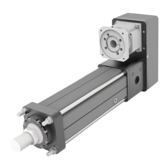
Figure 2: FTX Actuator with Parallel Motor Mount 1.5 Actuator Drive Train Configurations Exlar offers a base FTX Series actuator model for the greatest flexibility in application. The base actuator includes: a high performance satellite roller screw assembly, pre-loaded angular contact bearings, an... - Page 8 Exlar also offers an FTX Series actuator, which is the base actuator along with one of a variety motor mounting configurations, combined in one product package. Parallel and in-line mounting options are offered as standard configurations. The parallel motor mounting configuration...
-
Page 9: Installation
2.0 Installation 2.1 Mounting Configurations The actuators come with a variety of mounting configurations as well. Refer to the Exlar catalog to review what options are available on the desired frame size. 2.2 Mounting Considerations As with any linear actuator product, misalignment of the FTX Series actuator with respect to the load the actuator is being used to move is of great concern. -
Page 10: Motor Installation
2.3 Motor Installation 1. Remove parallel drive cover screws, washers, cover and gasket. The screws are hand tightened from the factory for shipment. 2. Attach motor or gearbox to motor plate using supplied mounting screws, washers and gasket. Curtiss-Wright | FTX Series Rev. - Page 11 3. Attach bushing and pulley to motor or gearbox output shaft and actuator input shaft. Refer to belt tensioning procedure for the approximate distance between the pulley and motor plate. Torque the Taper-Lock screws to specification. The Taper-Lock bushings can be used with or without a key. Figure 5: Motor and Pulley with Taper-Lock Bushing Curtiss-Wright | FTX Series Rev.
- Page 12 4. If the parallel drive assembly is supplied with a keyless style bushing, a key cannot be used. The bushing may have to be reversed to attain proper pulley distance. In some instances the bushing and pulley may have to be installed before the motor is attached to the motor plate to allow clearance for tightening the bushing.
- Page 13 5. Refer to section 3.3 for belt installation, belt tension and cover assembly. 6. For inline motor mounting, an elastomer jaw coupling is used. The coupling must be fitted flush to the end of the motor shaft. Figure 7: Inline Motor Mounting Figure 8: Coupling Alignment Curtiss-Wright | FTX Series Rev.
- Page 14 7. Torque coupling mounting screw to specification Figure 9: Coupling-Mounting Screw 8. Insert motor or gearbox as assembled into inline housing assembly. This is a blind assembly and may require reposition of motor coupling to match actuator coupling. Do not force installation or use motor mount screws to join pieces.
-
Page 15: Lubrication
2.4 Lubrication Grease Specification FTX Series actuators are shipped from the factory fully lubricated with high temperature grease. Exlar uses Mobilith SHC 220, a high performance, extreme-pressure grease. The unique physical properties of the synthetic base oil provide outstanding protection against wear, rust, corrosion and high or low-temperature degradation. - Page 16 Oil Specification The FTX and FTP Series use Mobil SHC 626 for oil fill. The actuator is shipped empty and only receives a light oil coating from the factory for initial test. The actuator must be filled by the customer for their specific application.
- Page 17 Horizontal Oil Fill If the actuator is to be used primarily in the horizontal orientation, the side sight glass will indicate a proper oil fill level. Either port can be used to fill the actuator depending upon the final orientation of the actuator. The correct fill is achieved when the oil level covers the lower sight glass completely.
- Page 18 Horizontal Oil Fill Vertical Oil Fill If the actuator is to be used primarily in the vertical orientation, the sight tube running the length of the actuator will be used to measure the oil fill level. Two magnetic plug ports are provided for fill and drain. Proper oil quantity will vary with the stroke of the actuator as well as the motion profile.
- Page 19 **Fill the Actuator with the Main Rod Retracted ONLY** Approximate Rod End Down Level Actuator FTX095-0150 0.25 0.26 FTX095-0300 0.80 0.84 FTX095-0600 1.90 2.00 FTX095-0900 2.99 3.16 FTX095 - Oil Qty. Per 25mm 0.091 0.096 of Stroke Approximate Rod End Up Level Actuator FTX095-0150 0.12...
- Page 20 Approximate Rod End Down Level Actuator FTX/P215-0150 2.11 2.23 FTX/P215-0300 4.68 4.95 FTX/P215-0600 9.83 10.39 FTX/P215-0900 14.98 15.83 FTX/P215 - Oil Qty. Per 25mm of 0.429 0.453 Stroke Approximate Rod End Up Level Actuator FTX/P215-0150 1.75 1.84 FTX/P215-0300 4.32 4.56 FTX/P215-0600 9.47 10.00...
- Page 21 Vertical Oil Fill Dimensions Vertical Oil Fill Dimensions Nut Length Bumper Height Actuator FTX095 110.1mm (4.33 in) 13.3mm (0.53 in) FTX125 128.1mm (5.04 in) 14.6mm (0.58 in) FTX/P215 199.2mm (7.84 in) 24.8mm (0.98 in) Curtiss-Wright | FTX Series Rev. C PN71855 5/26/17...
- Page 22 Vertical Oil Fill Example In this example a 300mm stroke FTX215 is running oil fill, rod down in the last 20mm of stroke. It is a high speed, low amplitude press with the cycle running 1-2 mm movement per press at high cycle rate. Most of the input power is being used in the last 20mm of stroke but the actuator can cycle once every hour to move tooling.
-
Page 23: Anti-Rotate System
2.5 Anti-Rotate Mechanism FTX Series actuators have an internal anti-rotate mechanism guided by extruded channels in the actuator case. The anti-rotates are comprised of a high performance, thermal and abrasion-resistant polymer. This precise mechanism will limit angular backlash and is designed to withstand the high force and speed created by these actuators. -
Page 24: Maintenance & Service
3.0 Maintenance & Service 3.1 Seals Both ends of the extruded housing on the FTX actuator are sealed using O-rings. The outer diameter of the output rod is sealed with a gland that utilizes a dual seal system with a wiper seal on the outside and a high pressure rod seal within the gland assembly. - Page 25 Seal Parts Grease and Oil Units Frame Description 50178 Wiper, AY, 1.75 inch ID 70635 Seal, BT, 1.75 inch ID FTX095 70755 Bearing, Linear Sleeve 10076 O-Ring, -137 Buna N70 63032 Wiper, AY, 2.25 inch ID 63033 Seal, BT, 2.25 inch ID FTX125 63034 Bearing, Linear Sleeve...
-
Page 26: Drive Train
3.2 Drive Train The FTX Series actuators are combined in a parallel motor mounting configuration using a synchronous belt. The drive train does not require any lubrication but any oil or dirt contamination within the belt drive system will decrease belt effectiveness and life. The belt and pulley system should be inspected periodically for excessive wear and proper tensioning. -
Page 27: Belt Tensioning
3.3 Belt Tensioning Procedure 1. Install motor, pulleys and bushings. The image below shows the proper distance to fix the pulley from the motor plate. See torque chart for bushing screw torque values. Belt centered on pulley width Figure 15: Belt Distance from Motor Plate 2. - Page 28 T-Bolt Idler Assembly Tension Adjustment Screw 3. The belt can now be placed onto the pulleys. 4. With the belt in place, the idler assembly can now be placed back over the T-bolt. Curtiss-Wright | FTX Series Rev. C PN71855 5/26/17...
- Page 29 Adjust the belt tension by first tightening the Idler Assembly Hex Nut to a point that assures the idler assembly is contacting the motor plate. Do not apply full torque at this point. Use the Tension Adjustment Screw to change belt tension ...
- Page 30 Proper Belt Tension Figure 17: Belt Tension Diagram These belt drives do not require as much tension as other belt drives that depend on friction to transmit the load. The installation procedure should begin by installing the belt with a snug fit. Now, measure the belt span length, (t), as shown in the picture above.
- Page 31 5. Fix the idler pulley in place by applying specified torque to the Idler Assembly Hex Nut. 6. Verify belt tension is at appropriate level after applying specified torque. Readjust if necessary. 7. Install Motor Plate Sealing Screw and sealing washer. Torque to spec.
-
Page 32: Roller Screw
3.4 Roller Screw The satellite roller screw used within the FTX Series actuators is a precision-machined mechanism, which is fully greased upon assembly. Lubrication of the roller screw should be maintained in accordance with section 2.3. The biggest enemies to this mechanism are shock loading and radial loads (side loads). -
Page 33: Inspection And Lubrication Procedure
3.5 Inspection and Lubrication Procedure The following disassembly and reassembling procedures are general guidelines. Individual designs may differ from these procedures and any questions should be verified with Exlar before reassembling and reinstalling the actuator into your machine or application. Drive train disassembly: 1. - Page 34 4. Remove screws from roller screw shaft pulley and use these same screws to push the pulley bushing off the pulley using the back out threads provided in the pulley or bushing. Then remove the motor pulley and bushing and remove the motor from the motor plate. Figure 19: Parallel Motor Mount Disassembly 5.
- Page 35 6. Loosen the motor or gearbox mount screws and remove assembly with coupling from the inline housing. 7. Remove motor plate screws and motor plate Figure 20: Inline Mount Motor Plate Removal 8. Remove nuts and tie rods or in some models, screws holding the adapter plate to the inline housing.
- Page 36 10. Loosen the actuator coupling mounting screw and remove coupling. (Note: For installation, the actuator coupling is mounted flush with the end of the input shaft.) Remove the inline housing adapter plate. 11. Installation is the reverse of removal. Curtiss-Wright | FTX Series Rev.
- Page 37 Grease Maintenance Procedure: The actuator will need periodic re-greasing based upon final use. The maintenance schedule will depend upon load, speed and duty cycle. High speed or load along with high duty cycle will need maintenance more often. The screw should be cycled its entire stroke periodically to redistribute grease, especially in short stroke applications.
-
Page 38: Optional Equipment
The FTX product has a variety of standard mounting options to couple to the end use system. These configurations vary based upon frame size. The Exlar catalog should be consulted to determine the desired model and mounting configuration. If a custom mount is required contact Exlar with the requirements. - Page 39 Normally Closed, Normally Open, Not Supplied Not Supplied Normally Closed, Normally Closed, Not Supplied Normally Open, Normally Closed, Normally Closed, Exlar Part Switch Type Supplier Part Number Number Normally Closed Switch, PNP 43404 Turck P/N: BIM-UNT-RP6X Normally Open Switch, PNP...
-
Page 40: Rod Ends
The equation that defines the amount of torque required for a corresponding thrust force is listed in the Exlar catalog. Reference this catalog for torque calculations and ratings. -
Page 41: Load And Speed Ratings
It is important to include any gearbox reduction and or drive train belt and pulley reduction into this equation as well. Reference the Exlar catalog for ratings and formulas regarding the linear speed of the FTX actuators. -
Page 42: Troubleshooting
All electrical problems associated with the motor used to drive the roller screw in an FTX actuator should be taken up with that motor manufacturer. Exlar will assist in contacting the appropriate person. If an externally mounted limit switch is not operating properly, check all power connections to the switch and make sure that the switch is wired properly. -
Page 43: Returning A Product For Repair
Exlar requires a purchase order at the time of RGA; $750 on warranty returns (refunded if warranty status is confirmed by the factory), or for the desired service package charge per unit on all non-warranty units. -
Page 44: Ftx095 Torque Specifications
7.0 Fastener Torque Specification 7.1 FTX095 Torque Specification FTX095 Torque Specification Part Loctite ft-lb in-lb Number Spec Fastener Description/Size Screw, M5x0.8 x 22mm, Gland to Face Plate Screw 48534 222MS SHCS, SS Tie Rod Nuts Nut, M10x1.5, SS 11586 Motor Plate to Bearing Screw, M10x1.5 x 30mm, 10987 Housing... -
Page 45: Ftx125 Torque Specifications
7.2 FTX125 Torque Specification FTX125 Torque Specification Part Loctite ft-lb in-lb Fastener Description/Size Number Spec Gland to Face Plate Screw Screw, M6x1.0 x 25mm, 40146 222MS SHCS, SS Tie Rod Nuts Nut, M12x1.75, SS 23511 Motor Plate to Bearing Screw, M12x1.75 x 35mm, 71020 Housing SHCS... -
Page 46: Ftx215 Torque Specifications
7.3 FTX215 Torque Specification FTX215 Torque Specification Part Loctite Fastener Description/Size Number ft-lb in-lb Spec Screw, M10x1.5 x 45mm, Gland to Face Plate Screw 67921 222MS SHCS, SS Nut, M20x2.5 Hex, Magni Tie Rod Nuts 69120 Coat Motor Plate to Bearing Screw, M16x2.0 x 40mm, 22599 Housing... -
Page 47: Ftp215 Torque Specifications
7.4 FTP215 Torque Specification FTP215 Torque Specification Part Loctite Fastener Description/Size Number ft-lb in-lb Spec Screw, M10x1.5 x 45mm, Gland to Face Plate Screw 67921 222MS SHCS, SS Nut, M30x3.5 Hex, Magni Tie Rod Nuts 69121 Coat Motor Plate to Bearing Screw, M16x2.0 x 40mm, 22599 Housing... -
Page 48: Motor Fastener Torque Specifications
7.5 Motor Fastener Mounting Torques Motor Mounting Torques (Stainless Steel Mounting Hardware) Screw Size Screw Size Inch Torque Metric Torque 8-32 19 lb-in (2.1 N-m) M2x0.4 2 lb-in (0.2 N-m) 10-32 29 lb-in (3.3 N-m) M2.5x0.45 7 lb-in (0.8 N-m) 1/4-20 62 lb-in (7 N-m) M4.x0.7...
Need help?
Do you have a question about the Curtiss-Wright FTX Series and is the answer not in the manual?
Questions and answers