Table of Contents
Advertisement
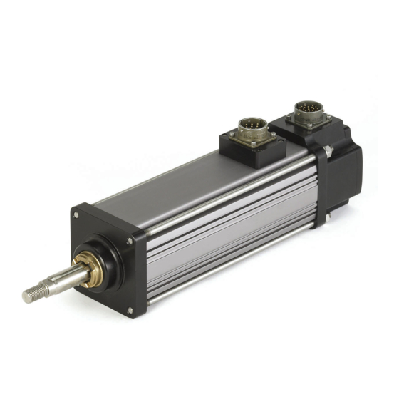
GSX and GS SERIES LINEAR ACTUATOR
INSTALLATION AND SERVICE MANUAL
Information furnished by EXLAR Corporation is believed to be accurate and reliable.
However, no responsibility is assumed by EXLAR
Corporation for its use. EXLAR reserves the right to change the design and operation of the equipment described herein and any associated
motion products that may appear in this document. Information in this document pertaining to equipment not furnished by EXLAR should be
confirmed by that equipment manufacturer. EXLAR assumes no responsibility for changes to information by other manufacturers or errors in that
information or the description of that information. Information in this document is subject to change without notice.
1
GS/X Manual.doc
02/17/14
PN: 10278
Exlar Corporation
Rev. KK
952-500-6200
Advertisement
Table of Contents

Subscribe to Our Youtube Channel
Related Manuals for Exlar GSX Series


Summary of Contents for Exlar GSX Series
- Page 1 However, no responsibility is assumed by EXLAR Corporation for its use. EXLAR reserves the right to change the design and operation of the equipment described herein and any associated motion products that may appear in this document. Information in this document pertaining to equipment not furnished by EXLAR should be confirmed by that equipment manufacturer.
-
Page 2: Table Of Contents
8.0 Certifications ..........Please visit www.exlar.com for information pertaining to connectors and cables. GS/X Manual.doc 02/17/14 PN: 10278 Exlar Corporation Rev. KK 952-500-6200... -
Page 3: Introduction
Seller's stated product warranty (see Terms and Conditions above), provided, however, that written notice of claimed defects shall have been given to Exlar within thirty (30) days from the date of any such defect is first discovered. The product(s) claimed to be defective must be returned to Exlar, transportation prepaid by Buyer, with written specification of the claimed defect. -
Page 4: Safety Considerations
CAUTION and WARNING signs as shown below. CAUTION WARNING Pay particular attention to these paragraphs. They are intended to provide you with helpful information to ensure safe and trouble-free installation. GS/X Manual.doc 02/17/14 PN: 10278 Exlar Corporation Rev. KK 952-500-6200... -
Page 5: System Configuration
The high torque to volume ratio available from a brushless motor, combined with the robust, high speed and high load capability of the planetary roller screw, make the Exlar line of linear actuators a true, all electric replacement for cumbersome high maintenance hydraulics. The use of electronic servo control provides simpler set up and more precise control than hydraulic systems as well. -
Page 6: Standard Actuator Pin-Outs And Connections
Many amplifiers offer software that allows the entering of parameters or the downloading of "motor data files" that dictate how the feedback must be set up on the motor. Exlar can provide many of these "motor files" or the proper parameters to enter. Entering motor parameter data to some amplifiers may require assistance from the amplifier manufacturer. -
Page 7: Cable Routing
2.5 Internal Holding Brake Many applications require the addition of the Exlar internal holding brake. The brake is held open by the supply of power to a magnetic/mechanical clutch. Whenever there is not power to the brake, the armature is held in place which prevents the inverted roller screw from turning and prevents the output rod from back driving, which in turn prevents the output rod from moving. - Page 8 Because of this change in technology, Exlar now provides the transient suppression diode separately from the actuator, for inclusion in the brake control circuitry as needed by the end user. A schematic, shown below, is provided with the shipped product showing the typical use of the transient suppression diode.
-
Page 9: External Limit Switches
10" Stroke 12" Stroke 14" Stroke 18" Stroke GSX20 5.515 8.515 12.500 14.515 GSX30 6.932 9.832 13.832 15.832 17.832 21.832 GSX40 9.832 11.83 13.832 15.832 21.832 GSX50 11.667 15.667 19.667 GSX60 10.461 14.461 GS/X Manual.doc 02/17/14 PN: 10278 Exlar Corporation Rev. KK 952-500-6200... -
Page 10: Brake Extensions
Normally Open Not Supplied Normally Closed Not Supplied Normally Closed Normally Closed Normally Open Normally Closed Switch Type Exlar Part Number Turck Part Number Normally Closed Switch 43404 BIM-UNT-RP6X Normally Open Switch 43403 BIM-UNT-AP6X 2.7 GS/X Linear Actuator Brake Extensions The brake option may add a third connector to the actuator and require a case extension to accommodate the internal components. -
Page 11: Anti-Rotation Option
For applications in which the load is free to rotate, Exlar offers the anti-rotation systems shown below. The drawings next page show the rod and bushing on only one side of the actuator. For long stroke actuators, the rod and bushing are required on both sides of the actuator. -
Page 12: Ingress Protection
3 Protected against solid objects over 2.5mm e.g. wire, small tools. 4 Protected against solid objects over 1.0mm e.g. wires. 5 Limited protection against dust ingress. (no harmful deposit) 6 Totally protected against dust ingress. GS/X Manual.doc 02/17/14 PN: 10278 Exlar Corporation Rev. KK 952-500-6200... -
Page 13: Installation And Operation
The following chart can be used to help determine oil vs. grease lubrication requirements: GS Series Actuators - Grease / Oil Operating Regions 100% Grease 100% RMS Applied Load as % of Maximum Rated Load GS/X Manual.doc 02/17/14 PN: 10278 Exlar Corporation Rev. KK 952-500-6200... -
Page 14: Grease Lubrication
There are several application and actuator configuration details that are involved in using a GSX with oil cooling, and any application that will use oil cooling must be discussed with Exlar Application engineering so that the correct actuator options can be selected, and the details of the application reviewed. -
Page 15: Mounting Configurations
A schematic of a possible example oil system is shown below. Exlar Application Engineering can assist you in the development of your own oil system, or suggest pre-packaged oil circulation systems. The maximum allowable internal oil pressure for the GS/X Series actuators is 10 psi. Take care to insure that this pressure limit is maintained. -
Page 16: Mounting Considerations
A GS/X Series actuator with the Side Mount option comes with threaded holes in the faceplate and endplate. Exlar recommends using hardened fasteners to mount a GS/X Series actuator to your machine frame. Exlar also recommends threading the mounting fastener into as much of the threaded hole in the actuator as possible, to prevent stripping out the threads in the actuator’s mounting holes. - Page 17 For applications requiring this type of impact, contact Exlar application engineering to insure that the actuator is properly sized or provisions made to absorb the induced energy.
-
Page 18: Manual Drive Operating Instructions
3.7 Manual Drive Operating Instructions Important: If manually driving through a brake or high force is necessary, please consult Exlar engineering. If a power tool is used to operate the manual drive the speed should be limited to 600 RPM An impact driver should never be used to operate the manual drive. -
Page 19: Maintenance Procedures
If your actuator has a preloaded roller screw, do not remove it from the cylinder. Preloaded screws require special tooling and procedures for proper disassembly and reassembly. Contact Exlar Corporation to arrange for maintenance of a preloaded screw actuator. Refer to the exploded view on the following page. -
Page 20: Lubrication Maintenance
Remove the screws for the spline assembly and remove it from the roller screw cylinder. The RB option requires removal of the feedback device to access and Exlar should be consulted for assistance, or the unit returned to Exlar. -
Page 21: Reassembly
Be sure that the faceplate seats completely and squarely on the front of the actuator. The inner surface of the faceplate provides the pre-loading for the bearings, and it is important that it is properly seated. GS/X Manual.doc 02/17/14 PN: 10278 Exlar Corporation Rev. KK 952-500-6200... -
Page 22: Seal Maintenance
A new main rod seal can be slid over the main rod, taking care not to touch the seal material to the threaded rod end. To have this service performed for you, contact Exlar Engineering or arrange with Exlar Returns Department to send your unit in for service. - Page 23 Main Rod Gland Seal and Bushing Note: Some actuators are provided with special rod gland seals due to chemical exposure or other special requirements. Contact Exlar if there is a question about your particular actuator having a standard material seal. Main Rod Seal Gland Installation/Replacement: 1.
-
Page 24: Troubleshooting Procedures
(receiving current) but is not If a motor file, or parameters specific to your amplifier/actuator operating or is operating combination have been supplied by Exlar, be sure that they are erratically. entered or downloaded properly. 2. Amplifier may be set up improperly for the particular motor being used. -
Page 25: Returning A Product For Repair
This provides one week from receipt of approval (by fax or email) for repair where parts are available PROCEDURE: Please discuss the return with Exlar Technical Support prior to requesting an RGA number to see if it is possible to resolve the issue prior to return. ... -
Page 26: Gsx Force Measuring Option
Input Impedance: 352 Ohms For specifications on other frame sizes please Output Impedance: 353 Ohms contact Exlar Applications Engineering Dept. Electrical Leakage: Infinite Meg Ohm 6.4 Wiring Code Wiring for the load cell connector depends on the type of connectors used on the actuator for power and feedback. If the connection option selects MS style connectors, an MS style load cell connector is used. -
Page 27: Class I Division 2 Option
NPT ports for customer conduit connection. It is the responsibility of the installer to insure that the interconnecting wire, cabling and conduit meet any local or regional required electrical codes and standards. 7.1 Terminal Box Wiring diagram GS/X Manual.doc 02/17/14 PN: 10278 Exlar Corporation Rev. KK 952-500-6200... -
Page 28: Class I Div 2 Terminal Box Terminations
7.2 Class I Division 2 Terminal Box Terminations Exlar uses spring clamp terminals for maximum vibration resistance and ease of connection Tin-plated terminals and stainless steel spring clamps for resistance to corrosion and vibration Spring clamp design to minimize stress relaxation and maintain contact force, even under vibration To use spring clamp terminals: 1. -
Page 29: Terminal Box Dimensions
7.3 Terminal Box Dimensions GSX50; GSX60 GSX30; GSX40 Note: Applications with 20A rms or greater will require the larger terminal box. GS/X Manual.doc 02/17/14 PN: 10278 Exlar Corporation Rev. KK 952-500-6200... -
Page 30: Certifications
8.0 Certifications GS/X Manual.doc 02/17/14 PN: 10278 Exlar Corporation Rev. KK 952-500-6200... - Page 31 GS/X Manual.doc 02/17/14 PN: 10278 Exlar Corporation Rev. KK 952-500-6200...
- Page 32 GS/X Manual.doc 02/17/14 PN: 10278 Exlar Corporation Rev. KK 952-500-6200...
- Page 33 GS/X Manual.doc 02/17/14 PN: 10278 Exlar Corporation Rev. KK 952-500-6200...
- Page 34 GS/X Manual.doc 02/17/14 PN: 10278 Exlar Corporation Rev. KK 952-500-6200...
- Page 35 GS/X Manual.doc 02/17/14 PN: 10278 Exlar Corporation Rev. KK 952-500-6200...
- Page 36 GS/X Manual.doc 02/17/14 PN: 10278 Exlar Corporation Rev. KK 952-500-6200...
Need help?
Do you have a question about the GSX Series and is the answer not in the manual?
Questions and answers