Table of Contents
Advertisement
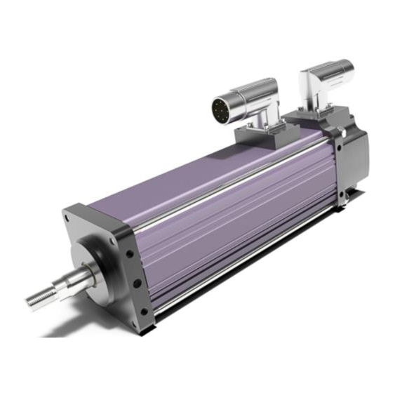
GSM Series Linear Actuator
Installation and Service Manual
Information furnished by Exlar Corporation is believed to be accurate and reliable.
However, no responsibility is assumed by Exlar Corporation for its use. Exlar reserves the
right to change the design and operation of the equipment described herein and any
associated motion products that may appear in this document. Information in this document
pertaining to equipment not furnished by Exlar should be confirmed by that equipment
manufacturer. Exlar assumes no responsibility for changes to information by other
manufacturers or errors in that information or the description of that information. Information
in this document is subject to change without notice.
This document does not contain any export controlled data.
Curtiss-Wright | GSM Series
Rev. U
PN29959
3/28/17
1
Advertisement
Table of Contents

Subscribe to Our Youtube Channel
Related Manuals for Exlar GSM20


Summary of Contents for Exlar GSM20
- Page 1 Information furnished by Exlar Corporation is believed to be accurate and reliable. However, no responsibility is assumed by Exlar Corporation for its use. Exlar reserves the right to change the design and operation of the equipment described herein and any associated motion products that may appear in this document.
-
Page 2: Table Of Contents
5.2 Class I Division 2 Terminal Box Terminations ......22 5.3 Terminal Box Dimensions ............24 6.0 Troubleshooting Procedures ............25 6.1 Returning a Product for Repair ........... 26 7.0 Certifications ................... 28 Refer to www.exlar.com for connector and wiring information. Curtiss-Wright | GSM Series Rev. U PN29959 3/28/17... -
Page 3: Introduction
(see Terms and Conditions above), provided, however, that written notice of claimed defects shall have been given to Exlar within thirty (30) days from the date of any such defect is first discovered. The product(s) claimed to be defective must be returned to Exlar, transportation prepaid by Buyer, with written specification of the claimed defect. -
Page 4: Safety Considerations
The high torque to volume ratio available from a brushless motor, combined with the robust, high speed and high load capability of the planetary roller screw, make the Exlar line of linear actuators a true, all electric replacement for cumbersome high maintenance hydraulics. The use of electronic servo control provides simpler set up and more precise control than hydraulic systems as well. -
Page 5: Typical System Wiring
Take care to insure that the amplifier has discharged all power. Typical System Connections 2.2 Typical System Wiring Please refer to www.exlar.com for information on connectors and wiring. 2.3 Feedback Information GSM Series actuators incorporate a quadrature incremental encoder with commutation signals as the primary rotary feedback device. - Page 6 Many amplifiers offer software that allows the entering of parameters or the downloading of motor data files that dictate how the feedback must be set up on the motor. Exlar can provide many of these data files or the proper parameters to enter. Entering motor parameter data to some amplifiers may require assistance from the amplifier manufacturer.
-
Page 7: Cable Routing
For applications in which the load is free to rotate, Exlar offers the anti- rotation systems shown below. The drawings on the next page show the rod and bushing on only one side of the actuator. -
Page 8: External Limit Switch Option
Anti-Rotate Option Dimensions Dimensions in inches GSM20 GSM30 GSM40 0.60 0.79 1.25 1.81 2.54 3.78 0.54 0.71 0.98 1.00 1.29 1.65 0.44 0.44 0.63 0.28 0.32 0.38 0.31 1.69 1.69 0.37 0.50 0.50 2.6 GSM Linear Actuator External Limit Switch With the anti-rotate option (Section 2.6) the GSM actuator can... - Page 9 External Limit Switch Dimensions DIM "A" 3" Stroke 6" Stroke 10" Stroke 12" Stroke 18" Stroke GSM20 5.515 8.515 14.515 GSM30 6.932 9.832 13.832 15.832 21.832 GSM40 9.832 13.832 15.832 21.832 The number of switches desired is selected by ordering the L1, L2 or L3 option, in which 1, 2, or 3 switches will be provided, respectively.
-
Page 10: Rear Brake Option
Historically, Exlar actuators and motors with holding brakes provided a transient suppression diode wired internally to the actuator or motor. With the changes in servo amplifier and control technology, there are now instances where the diode is not required to be within the motor. - Page 11 The rear brake option adds length to the dimensions of the GSM actuators as follows: (See drawings in Section 5.2.) GSM20: Add 1.784 inches (45.3 mm) if ordering brake GSM30: Add 1.6 inches (40.6mm) if ordering brake GSM40: Add 2.33 inches (59.2 mm) if ordering brake...
-
Page 12: Ingress Protection
DO NOT attempt to operate the actuator with the brake applied. Allowing the actuator to operate with the brake applied may cause serious damage to the actuator and/or the brake. Do not use the brake to support heavy loads while an operator is under the load. Provide another means to lock the load in position. -
Page 13: Installation And Operation
3.1 Lubrication Requirements The GSM Series actuator is shipped from the factory fully greased and ready for installation. Exlar recommends using Mobilith SHC 220, a high performance, extreme-pressure grease. The unique physical properties of the synthetic base oil provide outstanding protection against wear, rust, corrosion and high or low-temperature degradation. -
Page 14: General Operation
All of the above relationships require proper anti-rotation of the GSM Series actuator rod. For more information on sizing and selection of GSM Series actuators and servo amplifiers, consult the sizing and selection section of the Exlar catalog. Motor RMS current must be maintained at a level below the continuous current rating of the GSM Series actuator or damage to the motor stator will result. -
Page 15: Manual Drive Operating Instructions
For applications requiring this type of impact, contact Exlar application engineering to insure that the actuator is properly sized or provisions are made to absorb the induced energy. 3.5 Manual Drive Operating Instructions Important: If manually driving through a brake or high force is necessary, please consult Exlar engineering. -
Page 16: Maintenance Procedures
If your actuator has a preloaded roller screw, do not remove it from the cylinder. Preloaded screws require special tooling and procedures for proper disassembly and reassembly. Contact Exlar to arrange for maintenance of a preloaded screw actuator. Refer to the exploded view on the page 20. -
Page 17: Lubrication Maintenance
Preloaded screws require special tooling and procedures for proper disassembly and reassembly. Contact Exlar to arrange for maintenance of a preloaded screw actuator. 5. When the face plate is removed, the thrust bearing and the open end of the roller screw internally threaded cylinder (ITC) are visible. -
Page 18: Reassembly
Grease must reach the bearing just behind the bearing that is visible as well. Use the following amounts of grease for each size roller screw and bearing: GSM20: 0.5 in GSM30: 0.75 in GSM40: 1.00 in 4.3 Reassembly 1.) Rethread the roller screw into the internally threaded cylinder... -
Page 19: Seal Maintenance
To have this service performed for you, contact Exlar Engineering or arrange with Exlar Returns Department to send your unit in for service Curtiss-Wright | GSM Series Rev. - Page 20 19021 360 lb-in (40.67 N-m) Note: Some actuators are provided with special seals due to chemical exposure or other special requirements. Contact Exlar if there is a question about your particular actuator having a standard material main rod seal gland.
-
Page 21: Class I Division 2 Option
2. Remove the O-ring from the O-ring groove located inside the opening from which the seal was just removed. 3. Replace the O-ring with the O-ring supplied with the new main rod seal gland. 4. Taking care not to touch the seal material to any sharp rod features such as threads, slide the seal gland on to the actuator rod and to the face plate. -
Page 22: Terminal Box Wiring Diagram
5.1 Terminal Box Wiring Diagram 5.2 Class 1 Division 2 Terminal Box Terminations Exlar uses spring clamp terminals for maximum vibration resistance and ease of connection Tin-plated terminals and stainless steel spring clamps for resistance to corrosion and vibration ... - Page 23 3. Make sure exposed wire is in the clamp, not insulated wire. 4. Remove the screwdriver. The clamp pressure will keep the wire in place. No exposed wire should protrude past the cage opening Curtiss-Wright | GSM Series Rev. U PN29959 3/28/17...
-
Page 24: Terminal Box Dimensions
5.3 Terminal Box Dimensions GSM30, GSM40 6.0 TROUBLESHOOTING PROCEDURES This section provides you with guidelines and hints on troubleshooting various problems that may be encountered during installation and operation of your Exlar GSM Series actuator. Curtiss-Wright | GSM Series Rev. U PN29959 3/28/17... - Page 25 If a motor file or parameters specific to your operating or is amplifier/actuator combination have been operating erratically. supplied by Exlar, be sure that they are entered or downloaded properly. 2. Amplifier may be set up improperly for the particular motor being used. Check amplifier settings for number of poles, voltage, current, resistance, inductance, and inertia.
-
Page 26: Returning A Product For Repair
Exlar requires a purchase order at the time of RGA; $750 on warranty returns (refunded if warranty status is confirmed by the factory), or for the desired service package charge per unit on all non-warranty units. -
Page 27: Certifications
7.0 CERTIFICATIONS Curtiss-Wright | GSM Series Rev. U PN29959 3/28/17... - Page 28 Per EU directives implemented on April 20th, 2016 the following requirement for requirement must be followed by Importers and Distributors. The requirements for importers include: Importers shall indicate their name, registered trade name or registered trade mark and the postal address at which they can be contacted on the apparatus (unless that is not possible, in which case it should be included on the packaging or in an accompanying document).
- Page 29 Curtiss-Wright | GSM Series Rev. U PN29959 3/28/17...
- Page 30 Curtiss-Wright | GSM Series Rev. U PN29959 3/28/17...
- Page 31 Curtiss-Wright | GSM Series Rev. U PN29959 3/28/17...
- Page 32 Curtiss-Wright | GSM Series Rev. U PN29959 3/28/17...
- Page 33 Curtiss-Wright | GSM Series Rev. U PN29959 3/28/17...
- Page 34 Curtiss-Wright | GSM Series Rev. U PN29959 3/28/17...
- Page 35 CSA Certified Product The GSM Linear Actuators are marked as shown after passing a rigorous set of design and testing criteria developed by CSA International (C22.2 No. 139). This label indicates that CSA certifies this product to be safe when installed according to the installation guidelines and used with the scope of the product specifications.
Need help?
Do you have a question about the GSM20 and is the answer not in the manual?
Questions and answers