Table of Contents
Advertisement
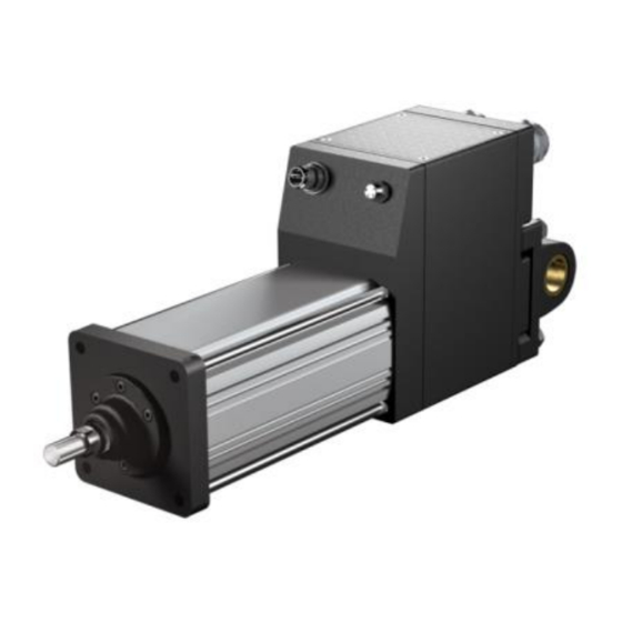
Tritex II™ DC Series Actuators
Models TDM/TDX 060 & 075, RDM/RDG 060, 075 & 090
48 VDC Linear and Rotary Actuator
Installation and Service Manual
Information furnished by Exlar Corporation is believed to be accurate and reliable.
However, no responsibility is assumed by Exlar Corporation for its use. Exlar reserves the
right to change the design and operation of the equipment described herein and any
associated motion products that may appear in this document. Information in this document
pertaining to equipment not furnished by Exlar should be confirmed by that equipment
manufacturer. Exlar assumes no responsibility for changes to information by other
manufacturers or errors in that information or the description of that information. Information
in this document is subject to change without notice.
This document does not contain any export controlled technical data.
Curtiss-Wright | Tritex II DC
Rev. J
PN49220
2/8/2016
1
Advertisement
Table of Contents

Subscribe to Our Youtube Channel
Related Manuals for Exlar Tritex II DC Series


Summary of Contents for Exlar Tritex II DC Series
- Page 1 Information furnished by Exlar Corporation is believed to be accurate and reliable. However, no responsibility is assumed by Exlar Corporation for its use. Exlar reserves the right to change the design and operation of the equipment described herein and any associated motion products that may appear in this document.
- Page 2 Terms and Conditions above), provided, however, that written notice of claimed defects shall have been given to Exlar within thirty (30) days from the date of any such defect is first discovered. The product(s) claimed to be defective must be returned to Exlar, transportation prepaid by Buyer, with written specification of the claimed defect.
-
Page 3: Table Of Contents
TABLE OF CONTENTS SAFETY CONSIDERATIONS ................4 CSA Certified Product ..................7 EU Declaration of Conformity for CE Mark ............9 TRITEX™ PRODUCT OVERVIEW ..............11 System overview, shown with SIO / Ethernet Option Board ......12 Tritex Configurations ..................12 60mm frame, top exiting connections, shown with 90 deg, M23 connectors .. -
Page 4: Safety Considerations
TROUBLESHOOTING PROCEDURES ............. 54 MAINTENANCE ....................55 Procedures for Roller Screw Re-Greasing ............55 ..............56 Lubrication Maintenance ................56 Grease Renewal ..................57 Reassembly Procedures for Complete Re-Greasing ............58 ..................58 Disassembly ..............59 Lubrication Maintenance ................59 Grease Renewal .................. - Page 5 can cause severe electric shock and/or burns and could be lethal. Extreme care is necessary at all times when working with or adjacent to the product. The installation must comply with all relevant safety legislation in the country of use. The forces created by actuator could be lethal or cause severe injury if proper protection is not provided to keep personnel away from moving components.
- Page 6 WARNING Supply isolation The AC supply or high voltage DC supply must be removed from the actuator using an approved isolation device or disconnect before any servicing work is performed, other than adjustments to the settings or parameters specified in the manual. The actuator contains capacitors which remain charged to a potentially lethal voltage after the supply has been removed.
-
Page 7: Csa Certified Product
65°C. - These conditions of acceptability only apply to units with a CSA mark on the product label. For additional information on cable installations or part numbers contact Exlar. Curtiss-Wright | Tritex II DC Rev. J PN49220... - Page 8 Curtiss-Wright | Tritex II DC Rev. J PN49220 2/8/2016...
- Page 9 Curtiss-Wright | Tritex II DC Rev. J PN49220 2/8/2016...
-
Page 10: Eu Declaration Of Conformity For Ce Mark
EU Declaration of Conformity for CE Mark Curtiss-Wright | Tritex II DC Rev. J PN49220 2/8/2016... -
Page 11: Tritex™ Product Overview
TRITEX™ PRODUCT OVERVIEW The Exlar Tritex Series of electric actuators combines an integrated brushless servo motor, amplifier and motion controller. Optionally the system can be configured for remote mounting of the amplifier and motion control 12–48V* DC Power Supply Digital and Analog I/O... -
Page 12: System Overview, Shown With Sio / Ethernet Option Board
System Overview, Shown with SIO / Ethernet Option Board Tritex Configurations The models TDM, TDX, RDM & RDG include the drive and motion controller integrated into the rear of the actuator. Various power and I/O connections are available. 60 mm frame sizes have top exiting 90 degree M23 connectors (shown below), or embedded leads connection options. -
Page 13: 60Mm Frame, Top Exiting Connections, Shown With 90 Deg, M23 Connectors
M23 I/O connector M23 Power connector Ethernet (Optional) Communications Connector 60 mm Frame, Top Exiting Connections, Shown with 90 Degree, M23 Connectors Communications Connector Field wiring access M23 I/O connector M23 Power Ethernet connector (Optional) 75 & 90 mm Frame, Rear Exiting Connectors, Shown with M23 Connectors Curtiss-Wright | Tritex II DC Rev. -
Page 14: General Specifications
General Specifications Drive Specification for all Tritex II DC Models with embedded drives Embedded Drive Specifications 12-24VDC nominal for CSA certified installation Input Voltage, 12-48VDC nominal for general use Bus and Logic Internal logic remains active with Bus or Logic power at 9V min 12-24V nominal, 30V max, 9V min Models with brakes require 24V +/- 10% for brake operation I/O Power... -
Page 15: Installation
Lubrication The TDM / TDX Series actuators are shipped from the factory fully greased and ready for installation. Exlar recommends using Mobilith SHC 220, a high performance, extreme-pressure grease. The unique physical properties of the synthetic base oil provide outstanding protection against wear, rust, corrosion and high or low-temperature degradation. -
Page 16: Outdoor And Wash Down Installations
Caution, over tightening can strip the threads in the enclosure. If a screw is missing replace it with Exlar PN 01185. (4-40 x ¼ Button Head Cap Screw, Stainless Steel) Curtiss-Wright | Tritex II DC Rev. -
Page 17: Manual Drive Operating Instructions
Important information to avoid damage to the manual drive If manually driving with a brake engaged or high force is necessary, please consult Exlar Application Engineering. If a power tool is used to operate the manual side drive the speed should be limited to 600 RPM ... - Page 18 Side Drive Instructions 1) Isolate all sources of energy from the drive 2) Press down on the hex until you feel you have bottomed out the manual drive. Constant downward force is required to maintain engagement during operation. 3) Give the hex a slight turn while observing if you are moving the rod or not.
- Page 19 Dimensions Curtiss-Wright | Tritex II DC Rev. J PN49220 2/8/2016...
- Page 20 Curtiss-Wright | Tritex II DC Rev. J PN49220 2/8/2016...
- Page 21 Curtiss-Wright | Tritex II DC Rev. J PN49220 2/8/2016...
- Page 22 Curtiss-Wright | Tritex II DC Rev. J PN49220 2/8/2016...
- Page 23 Curtiss-Wright | Tritex II DC Rev. J PN49220 2/8/2016...
-
Page 24: Electrical Installation
Electrical Installation Introduction All of the required power components and motion processor are contained in the actuator or drive housing. Main Power Supply Selection The Tritex actuator requires DC power from a power supply or batteries. The actuator will operate on voltages from 12-48V DC nominal. The continuous operating range is 10-53V DC. -
Page 25: Unregulated Ac/Dc Power Supplies
Different considerations pertain to each type, and each has advantages and disadvantages. Exlar offers a 48V unregulated supply rated at 10 amps continuous output, TTPS1048 (see Accessories section). It can deliver about 450W continuous output power. Due to its higher output voltage at light load, it may be necessary to connect to a higher voltage tap, such as the 132V tap for 120V operation. - Page 26 It may be necessary to use a blocking diode to allow the bus voltage at the drive to rise above normal supply voltage without any reverse current. Exlar offers a Power Distribution and Surge Filter assembly that include a blocking diode, TDCESF1 (see Accessories section).
-
Page 27: Power From Battery Systems
Power from Battery Systems Tritex II DC is designed to be powered directly from 12V and 24V lead- acid batteries in vehicles. Regen energy and ripple current are not generally of concern with battery applications of this type. Battery systems generally will be able to supply peak power to the actuator. The average power may be a consideration in sizing the charging circuits for the battery system. -
Page 28: Handling Regen Energy - External Shunt Resistor And Regulator
30 volt limit. Notice there is no external diode, isolating the power supply from the Bus voltage. For this example, set the User Overvoltage Fault Limit to 33 V. The Tritex shunt regulator will attempt to limit the Bus Voltage to 30 volts (90% of 33 V) to protect the power supply from overvoltage faults &... - Page 29 share a return path. Logic Power can be the same wide range as the main power supply, 12 V, 24 V, or 48 V nominal, and can handle the regen voltages that appear on the main supply. A single supply may be used for both with a relay contact in series with the main supply positive connection to remove bus power.
- Page 30 Regulator Input Power Common Un-Regulated Power Supply for Logic and Bus power, with a Shunt Regulator Such as Exlar TTSR1 CAUTION Reversing polarity of the Bus Power (+) and Power Common (-) will cause a short circuit, which must be protected by the input fuse.
-
Page 31: Shielding
When the “I” connector option and Exlar cables are used this function is included in the cable / connector construction at the actuator end. NPT Connections When the connector option “N”... -
Page 32: Grounding
Grounding _____________________________ WARNING The actuator and all power supply PEs and negative connections must be properly grounded using a single point grounding method. Incoming AC Supply Fuse Single point GND (bonded to enclosure) Fuse Actuator Ground & Power Cable Shield DC Supply 24/48 V dc Power/Logic... -
Page 33: Power Supply Connections
Power Supply Connections Power Connector Pin-Out, M23 Connectors, “I” Connector Option Pin for “I” Wire Color Connector “B” Option Signal Option TTIPC Bus Power (+) 12-48 V dc Blue Logic Power (+) 12-48 V dc White Blue Power Common (-) Black Black PE (GND) - Page 34 Power Connections on Terminal board 75 mm and 90 mm Terminal Minimum Wire Label for “N” or “G” Signal AWG. Bus Power (+) 12-48 V dc Bus + Power Common (-) COMMON Logic Power (+) 12-48 V dc LOGIC + PE (GND) Curtiss-Wright | Tritex II DC Rev.
-
Page 35: Tritex Input And Output Wiring
Tritex Input and Output Wiring Input / Output Connections with M23 connectors 19 Pin I/O Connector for I Connector Options. Pin for “I” Connector Wire Color Code TTIOC Cable and “B” Connector Option FUNCTION Option White/Yellow INPUT1 White/Red INPUT2 White/Green INPUT3 White/Black INPUT4... -
Page 36: Input/Output Connections
Input / Output Connections Terminal board connections for 75 mm and 90 mm only Terminal # Function Terminal # Function Terminal # Function Field I/O *Analog IN+ INPUT 1 Com. INPUT 2 Brake *Analog IN- Power + INPUT 3 Brake *Analog Power + Field I/O... -
Page 37: Canopen
CANopen The CANopen circuit is optically isolated from the drive main power. There are two methods of connecting to the Tritex with the CANopen option. If the connector option (COP) is chosen, the only option available for 60mm actuators, a five pin connector (Turck FS 57-.1) will be presented to the user for connection or “T-ing”... -
Page 38: I/O Power Supply
I/O Power Supply The digital inputs and outputs are optically isolated from the other power supplies. If it is desired to maintain this isolation, a separate power supply must be used with an output within the range of 10 V to 30 V dc. Two Power Supply Configuration Fuse Logic Power... -
Page 39: Digital Inputs
Fuse Logic Power 24 V dc Fuse Fuse Bus Power Regulated Power 200 V, if required AC Input Power Supply Connector Power Common Field I/O Common Connector Field I/O Power Single Power Supply Configuration Digital Inputs Tritex digital inputs are optically isolated from drive main power, but have a common negative side. -
Page 40: Digital Outputs
Digital Outputs The Tritex digital outputs are optically isolated from drive main power, but have a common positive side. SIO and Ethernet options have four outputs; the IA4 option has three outputs. These outputs are sourcing only, they provide a positive voltage when on. The outputs have short circuit and thermal protection, and protection against inductive kick at turn-off. -
Page 41: Actuator Brake Option
Actuator Brake Option The actuators may be ordered with a brake option. This brake is intended as a “parking brake” and is not intended for use as “stopping brake”. The brake engages when the brake voltage is removed. Brake voltage is 24 V +/- 10%. Since the Brake and I/O power supplies are interconnected, use of a brake places additional voltage and power constraints on the I/O supply. -
Page 42: Analog Input
Analog Input An analog input is provided for use as a position, velocity or current command. Differential input range is -10 V to +10 V. Input range on Analog IN+ is -15 V to +15 V with respect to I/O Common. Input range of Analog IN- is -15 V to +12 V with respect to I/O Common. -
Page 43: Analog Output
Analog Output A 0-10 V analog output is provided. The function of this output is programmable. It can be used for position, velocity or current monitoring. The intent of this output is to provide a “monitor” type value not a “control”... - Page 44 8mm communications connector 8mm communications connector Front view Optional RS 485 Field Wiring for 75 mm and 90 mm 8 mm Wire Color for Function Number TTCOM Terminal # 485+ Brown 485- Blue 485 COM Black Shield Drain Curtiss-Wright | Tritex II DC Rev.
-
Page 45: Pc Communications
PC communication ports and the RS485. This can be either a USB to 485 converter, such as the Exlar CBL-T2USB485-M8 or any other standard 485 converter. See Accessories section. +3.3V... -
Page 46: Ia4 Option Board Connections
RS485 is a “multi-drop” network as opposed to a “star”, therefore keep the drop (stub) to each actuator as short as possible. When using the 8 mm connector use a T connector, such as the Exlar PN TT458SP. ... - Page 47 4-20 mA input connection Tritex External Controller Option or Transmitter 4-20 mA Output Power Supply + 4-20 mA Input To CPU Converte 24V Com - 4-20 mA Input Connection to High Side Controller Connection to Low Side Controller 4-20 mA Input Specification: Description Specification 2 mA to 22 mA...
- Page 48 4-20 mA Output The 4-20 mA output is a two wire circuit; it requires an external loop supply of 12 to 30V DC to generate the isolated supply voltages needed. The Tritex circuit requires 8V to operate; therefore the max impedance the output can drive is dependent on the loop supply voltage.
-
Page 49: Af Option, Absolute Feedback
The replacement battery kit (Order Exlar PN 42712) may contain a different mounting clip and connector that are not used in this application and should be discarded. For 60 mm Curtiss-Wright | Tritex II DC Rev. -
Page 50: Ethernet Options, Eip,Tcp Or Profinet
The battery is mounted remotely and wired through the power connector. The replacement battery only is Exlar P/N 50748. Observe battery polarity when installing replacement battery in clips. Important: If the battery is removed with both Motor and Logic power also removed, leave all power off and do not reconnect the battery for 4 minutes. - Page 51 Cord sets Signal Name Transmit + (TX+) Pair Transmit – (TX-) Receive + (RX+) Pair Receive - (RX-) M12 D Coded Straight through Cord Set 8-Way Modular M12 Signal Pair Pair Conversion from M12 D Coded to 8-way Modular Straight through Cord Set Curtiss-Wright | Tritex II DC Rev.
-
Page 52: Emc Considerations
Shielded or Unshielded Cables The Tritex can be used with either shielded or un-shielded Ethernet cables. If a shielded cable is used it is important that the shield is not connected at the Tritex M12 end of the cable. Off the shelf shielded Ethernet cables with M12 connectors usually connect the shield through the M12 connector coupling nut, be sure the shield is not connected to the Tritex end of the coupling nut. - Page 53 Cable Shield Grounding Example Curtiss-Wright | Tritex II DC Rev. J PN49220 2/8/2016...
-
Page 54: Troubleshooting Procedures
2. Drive is improperly tuned (wrong gain settings). Output rod rotates 1. Install Exlar anti-rotation assembly or incorporate during motion and thus anti-rotation into the application. does not provide proper linear motion. -
Page 55: Maintenance
If your actuator has a preloaded roller screw, do not remove it from the cylinder. Preloaded screws require special tooling and procedures for proper disassembly and reassembly. Contact Exlar to arrange for maintenance of a preloaded screw actuator. Disassembly Refer to the exploded view on the following page. -
Page 56: Lubrication Maintenance
Lubrication Maintenance Exlar recommends using Mobilith SHC 220, a high performance, extreme-pressure grease. Grease lubricated units will require periodic inspection and renewal of the roller screw grease. The table below shows the recommended grease renewal period. Recommended Grease Renewal Period (hours) -
Page 57: Reassembly
1.) Use a brush to work approximately 0.5 in of grease for every 3 inches of stroke length into the roller screw cylinder. Be sure to cover all of the threaded areas of the cylinder. 2.) Use a brush to work grease in to the roller screw assembly. Be sure to cover all the threaded surfaces of the screw assembly. -
Page 58: Procedures For Complete Re-Greasing
Tritex 60 & 75: 10 in-lbs (0.83 lbf-ft, 1.13 N-m) 4.) If your actuator has an external anti-rotate mechanism, slide the rod or rods of the anti-rotate mechanism through the front flange and into the guide bushing or bushings mounted to the rear of the flange. -
Page 59: Lubrication Maintenance
Lubrication Maintenance Exlar recommends using Mobilith SHC 220, a high performance, extreme-pressure grease. Grease lubricated units will require periodic inspection and renewal of the bearing and roller screw grease. The table below shows the recommended grease renewal period. Recommended Grease Renewal Period (hours) -
Page 60: Reassembly
1.) Use a brush to work approximately 0.5 in of grease for every 3 inches of stroke length into the roller screw cylinder. Be sure to cover all of the threaded areas of the cylinder. 2.) Use a brush to work grease in to the roller screw assembly. Be sure to cover all the threaded surfaces of the screw assembly. - Page 61 3.) Carefully slide the face plate and bushing/seal assembly over the actuator rod end, while guiding the tie rods through the holes in the rear end cap of the actuator. The seal is a tight fit on the rod end. Take care not to damage the seal on the threads of the extending rod.
-
Page 62: Accessories
ACCESSORIES Cables TTIOC-xxx I/O Cable Curtiss-Wright | Tritex II DC Rev. J PN49220 2/8/2016... -
Page 63: Ttipc-Xxx Power Cable
TTIPC-xxx Power Cable Curtiss-Wright | Tritex II DC Rev. J PN49220 2/8/2016... -
Page 64: Ttico-Xxx Communications Cable
TTICO-xxx Communications Cable Curtiss-Wright | Tritex II DC Rev. J PN49220 2/8/2016... -
Page 65: Communication Converters
Communication Converters When connecting the Tritex RS485 port to PC, a communication converter will typically be required. Exlar offers a USB to RS485 converter with an M8 connector ready to connect to the Tritex port. Model # CBL-T2USB485-M8-xxx. This converter is not isolated and is not recommended for permanent installation. - Page 66 Specifications AC Input: 108/120/132/216/240/264 VAC @ 47-63 Hz Output Ripple: 3% RMS at full rated load Efficiency @ Full Load 80% typical UL Recognized for USA and Canada File Number E133338 TUV Rheinland licensed. Certificate no. R 9675002 Complies with the requirements of standard EN 60590 and low voltage directive 72/23/EEC TTPS1048 Power Supply Output Voltage Typical DC Output Voltage @ Nominal Input Voltage...
-
Page 67: Shunt Regulator
Shunt Regulator TTSR1 Shunt Regulator Option Transient over voltage problems are quickly solved using shunt regulators that clamp regeneration voltage to safe levels. These simple devices can increase system reliability by stabilizing voltage fluctuations and eliminate over-voltage shutdowns. The purpose of a shunt regulator is to 'burn off' excess regeneration energy that is produced when a drive brings a large load to a stop. - Page 68 Specifications Fuse: 3A motor delay rated @ 250 VAC Filter Capacitance: 1200 µF Dissipation Capabilities: 95W Resistance: 5 Ohms Size: 8.00 x 4.25 x 2.63 inches (203.2 x 108.0 x 66.7 mm) Weight: 0.8 lbs (0,36 kg) Wiring Detail TTSR1 Dimensions Curtiss-Wright | Tritex II DC Rev.
-
Page 69: Power Distribution And Surge Filter
Power Distribution and Surge Filter TDCESF1 Power Distribution and Surge Filter Accessory This accessory was designed to eliminate surge transients across + and – lines on a DC power source in order to pass EMC testing as a stand-alone device. It will seldom if ever be needed for that purpose because the Tritex II DC device will be connected to a power source that does not pass this type of transient. - Page 70 The red wire labeled “Power Link” from J5 to J6 connects Pwr+ to BusPwr through fuse F1. If a blocking diode is required to prevent regen power from flowing back to the power supply, the Power Link can be clipped out at J5 and J6, which then allows the internal blocking diode to operate.
Need help?
Do you have a question about the Tritex II DC Series and is the answer not in the manual?
Questions and answers