Table of Contents
Advertisement
Quick Links
Series 1400
SELECTRONIC
Installation and Operation Manual
Please read the following information before installing. This installation information is intended for all Series 1400 models.
FOUR STAGE ENGINE DRIVEN operation information– see Attachment S14E-92229N.
FOUR STAGE ELECTRIC MOTOR DRIVEN operation information–see Attachment S14M-92230N.
WARNING
BEFORE BEGINNING INSTALLATION OF THIS MURPHY PRODUCT
Disconnect all electrical power to the machine.
Make sure the machine cannot operate during installation.
Follow all safety warnings of the machine manufacturer.
Read and follow all installation instructions.
Suitable for Class I, Division 1, Group D,
Hazardous Locations
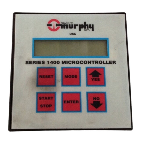
Description
The S1400 is a microprocessor based fault annunciator. It tells in
alphanumeric characters which protective device has signaled an alarm
or caused equipment shutdown. Basic programming for each application
is completed at Murphy and can be changed in the field by simply plug-
ging in a new preprogrammed microchip. A digital output version
(S1400-SP) interfaces with micro-controllers (7 bit straight binary code).
The basic system consists of (1) the module, (2) terminal block assembly
(32 position rail mount), (3) a 36 inch (914 mm) flat ribbon cable for con-
nection of the terminal block to the monitor, and (4) a power supply
which includes the control Inputs/Outputs and an intrinsically safe barrier
with cable assembly.
The S1400 and S1400-SP are powered from a 120 VAC or 12/24 VDC,
Class I, Division 1 explosion-proof power supply. The monitor is rated
intrinsically safe.
Module
The S1400 module is the brain of the annunciator system. It contains a
microcomputer, a 32 point multiplexer, a dot matrix alphanumeric dis-
play and a 6-button membrane keypad for operator access to field
adjustable functions. (See figure, p-2.)
Display
The S1400 module displays each mode of operation. The display is a dot
matrix alphanumeric 32-character display. By observing the monitor the
operator can determine the operating status of the control system.
Power Supply
An explosion-proof enclosure designed for Class I, Division 1, Group D
hazardous locations (CSA approved.) contains the supply voltage condi-
tioning circuits, battery charger, module power supply, backup batteries
®
Annunciator
.
Installation Accessories
Hardware, tools, and optional equipment needed to install the S1400.
For CD ignition applications use an S14RSA92 adapter.
(See Opto-isolator note under specifications section, p-2).
For normally open prelube permissive function use a 20P100
SWICHGAGE
®
or a suitable pressure switch. For normally
closed prelube permissive function use a 20EO-100 SWICHGAGE
or a suitable pressure switch. (See Permissive Function, p-2.)
Mounting rail (see page 3 for specifications).
Hardware for power supply mounting (four
bolts or machine screws, 1-
Tools as needed for the system mounting, needle nose pliers,
set of sockets, blade type screwdriver.
18 ga. wire for extension and hook up. Set of wire terminating
tools and wire terminations such as ring or spade terminals.
and the intrinsically safe barriers for isolation between the power supply
and the low energy module circuits. The power supply accepts 120 VAC,
50-60 Hz and/or 12-24 VDC input power. 24 VDC power can be used as
primary power or as a backup source of power when 120 VAC is used.
120 VAC power is connected between terminals #1 and #2 of the 18 posi-
tion power input and output terminal block. 24 VDC is connected between
terminal #3 and #4, with terminal #3 positive with respect to terminal #4.
Control Relays
The power supply has four control relays to provide form "C" SPDT
outputs. The output relay functions for Four Stage Electric Motor Driven
applications are: lube control, drive motor, cooler motor, and alarm.
The output relay functions for Four Stage Engine Driven applications
are: lube control, ignition ground, fuel valve control, and alarm. Relay
functions for custom programs will depend upon specific application.
Four light emitting diodes (LED's) located adjacent to the relays, turn
ON to indicate when the relays are energized.
System Input Terminal Block
Sensor input terminal block consists of a 64-position, 32 pair input rail-
mount terminal block for interface of panel or field-mounted end
devices. End devices must be mechanical switches (non energy storing
devices). The terminal block can be used for Normally Open sensors
(one wire), and/or Normally Closed sensors (two wires). Factory
installed jumpers are supplied for each sensor input.
Ribbon Cable
A 36 in. (914 mm) flat ribbon cable is required for connection of the
S1400 module and the sensor input terminal block. The cable is supplied
with two D-sub 37 PIN connectors at each end of the cable.
B
S14-92134N
Revised 03-94
Section 50
5
/
in. [8 mm] size
16
1
/
in. [38 mm] minimum length).
2
®
®
1
Advertisement
Table of Contents

Subscribe to Our Youtube Channel
Related Manuals for Murphy SELECTRONIC 1400 Series


Summary of Contents for Murphy SELECTRONIC 1400 Series
- Page 1 120 VAC is used. is completed at Murphy and can be changed in the field by simply plug- 120 VAC power is connected between terminals #1 and #2 of the 18 posi- ging in a new preprogrammed microchip.
- Page 2 Program Memory: Memory held in EPROM, 4k, 192 bytes of RAM. Sensor Inputs: For up to 32 normally open (NO) and/or normally closed Backup Battery: Recharged during normal operation. Provides up to (NC) sensor inputs such as Murphy SWICHGAGE ® control instru- 5 hours backup time.
- Page 3 MOUNTING DIMENSIONS WARNING: Perform the mounting operation with power source off. The S1400 module was designed to be mounted within a weatherproof enclosure. It is intended for mounting in a flat panel. First, cut a square mounting hole of 3- in.
- Page 4 HAZARDOUS AREAS INSTALLATION WARNING: For hazardous application requirements, the S1400 complete system must be installed in accordance with the National Electrical Code (NEC) Class I, Division 1, Group D (article 504) specifications, and per Murphy drawing HC12046. Sensor Input Ribbon Cable...
- Page 5 SYSTEM TYPICAL HOOK UP CAUTION: Perform the wiring operation with the power source “OFF” and the area made non-hazardous. Make sure the voltage and current requirements are within the S1400 system ratings. Conduit is required to protect wires from damage. REFER TO THE SPECIFIC SYSTEM APPLICATION WIRING DIAGRAM SUPPLIED WITH YOUR UNIT.
- Page 6 NOTE: If shutdowns still result, send the complete system back to us. WARRANTY A two year limited warranty on materials and workmanship is provided with this Murphy product. Details are available on request and are packed with each unit. In order to consistently bring you the highest quality, full featured products, we reserve the right to change our specifications and designs at any time.
Need help?
Do you have a question about the SELECTRONIC 1400 Series and is the answer not in the manual?
Questions and answers