Table of Contents
Advertisement
Advertisement
Table of Contents

Subscribe to Our Youtube Channel
Related Manuals for Murphy PV485


Summary of Contents for Murphy PV485
- Page 1 ® PowerView Model PV485 Installation Manual 00-02-1018 2017-05-23 Section 78...
- Page 2 In order to consistently bring you the highest quality, full-featured products, we reserve the right to change our specifications and designs at any time. The latest version of this manual can be found at www.murphybyenovationcontrols.com. BEFORE BEGINNING INSTALLATION OF THIS MURPHY PRODUCT: Read and follow all installation instructions.
-
Page 3: Table Of Contents
Wiring Instructions 4 PIN Specifications for AMPSEAL Style Connection .............4 Accessories ........................4 Configuration Information ......................5 Specifications ..........................6 Technical ........................6 Environmental ......................6 Mechanical ........................6 Mounting Templates ........................7 Dash-Mount Template ....................7 Rear-Mount Bracket Template ..................9 PV485 Connection with Power ....................11... - Page 4 (THIS PAGE INTENTIONALLY LEFT BLANK)
-
Page 5: Hardware Installation
Hardware Installation The following instructions will guide you through installing the PV485 display. Inspecting Package Contents Before attempting to install the product, it is recommended that you ensure all parts are accounted for and inspect each item for damage (which sometimes occurs during shipping). -
Page 6: Rear-Mounted Installation (Optional)
Installing the Display Place the back side of the display through the opening in the dash. 1. Use the 4 screws to line up the unit with the drilled holes. 2. Push the unit through the opening and screws through the drilled holes until the back of the case is flush. - Page 7 Studs 1. Use the Installation Template (included at the end of the manual) as a guideline to cut a hole in the mounting plate to the specified dimensions and weld 8-32 studs where indicated on the template for mounting. NOTE: Weld Studs and nuts are not provided. 8-32 Keps Nuts, Lock Nuts, or Nuts with lock washers would need to be used.
-
Page 8: Wiring Instructions
Wiring Instructions PIN Specifications for AMPSEAL Style Connection Accessories P/N 78-00-0824 – Wiring Harness, Loose leads, 24 inches P/N 78-09-0077 – Programming Harness Section 78 00-02-1018 2017-05-23 - 4 -... -
Page 9: Configuration Information
Connect the USB drive to the USB port on the connector provided with the programming kit. Turn off the PV485, and turn it back on while holding down display key 5 (the button on the far right). Continue to hold the button a few more seconds, then release. -
Page 10: Specifications
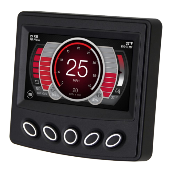
Specifications Technical Display: Bonded 4.3” color transmissive TFT LCD Resolution: WQVGA, 480 x 272 pixels, 16-bit color Aspect Ratio: 16:9 Orientation: Landscape Backlighting: LED, 900-1000 cd / m2 (30,000 hr lifetime) Microprocessor: Freescale iMX35 32bit, 532Mhz Operating System: QNX Real-Time Operating System Flash Memory: 256 MB (expandable to 8GB) RAM: 128 Mbytes DDR2 SDRAM Operating Voltage: 6-32 VDC, protected against reverse polarity and load-dump... -
Page 11: Mounting Templates
Mounting Templates Dash-Mount Template NOTE: These templates are as close as possible to the actual size needed for unit placement. Always remember to measure twice to ensure correctness before cutting the dash material. Section 78 00-02-1018 2017-05-23 - 7 -... - Page 12 Section 78 00-02-1018 2017-05-23 - 8 -...
-
Page 13: Rear-Mount Bracket Template
Rear-Mount Bracket Template Section 78 00-02-1018 2017-05-23 - 9 -... -
Page 15: Pv485 Connection With Power
PV485 Connection with Power Section 78 00-02-1018 2017-05-23 - 11 -...
Need help?
Do you have a question about the PV485 and is the answer not in the manual?
Questions and answers