Table of Contents
Advertisement
Quick Links
Tachometer and Tachometer/Hourmeter Installation
Instructions for Series: ATS, ATHS, ATA, ATHA
Please read the following instructions before installing. A visual inspection is recommended before mounting.
General Information and these installation instructions are intended for all Tachometer and Tachometer/Hourmeter models.
WARNING
BEFORE BEGINNING INSTALLATION OF THIS MURPHY PRODUCT
Disconnect all electrical power to the machine.
Make sure the machine cannot operate during installation.
Follow all safety warnings of the machine manufacturer.
Read and follow all installation instructions.
Description
These tachometers are indicators of engine revolutions per minute (RPM). Models
equipped with hourmeter also record elapsed, engine running time.
The alternator driven models are designed to function from pulses generated by an alter-
nator with 4, 8, 12, 14, or 16 poles on the rotor.
For magnetic sensor (pickup) driven models, the pulses can be obtained from the ring
gear of an engine by means of an electromagnetic sensor (pickup). Magnetic sensor
driven models are designed for flywheels having anywhere from 70 to 225 teeth.
All units are for negative ground, positive ground or isolated electrical systems. If the
instrument is connected reverse polarity, it will not operate until proper connections are
made. All units are powered by 12 VDC. For 24 VDC applications, a ATVC12/24 con-
verter must be used (see Fig. 3 or Fig. 5).
Specifications
Power Input: 12 VDC (11.5 – 16 V) [0.84 to 1.44W].
Backlight: 3 to 4.7W
RPM Input Signal Voltage: 1.5 Vrms minimum from a magnetic pickup or
alternator (minimum 3-pole).
Accuracy: Tachometer: ± 2% full scale. Hourmeter: ± 0.01% hours, ± 1 count.
Temperature Range: -5°F to 185°F (-20°C to +85°C).
Dial (Face Plate): 270° sweep with white numerals (over black background)
Bezel: 304 Stainless Steel.
Scale: 0-3000 RPM and 0-4000 RPM (ATHA-40-12-A model only)
Case Material: Plastic.
Hourmeter Range: Measures elapsed time: 100,000 hours in 0.1 increments.
Mount these units in a place where they will be protected from rain and splashing
water. A minimum distance of 12 in. (305 mm) from any coil, coil leads, or high volt-
age wiring should be maintained. These units are intended for mounting in a flat
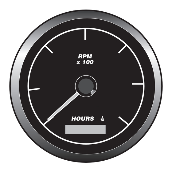
Front View
RPM
x 100
1
HOURS
10
3-53/64 in.
(97 mm)
GENERAL INFORMATION
Basic Models
Magnetic Sensor (Pickup) Signal Tachometer 70 - 225 pulses 12 VDC
2733Hz to 13.62 kHz@3000 RPM
ATS-30-12
ATS-30-12-A
ATS-30-12-B
ATS-30-12-C
ATHS-30-12
ATHS-30-12-A Tachometer/Hourmeter w/ Black Stainless Steel Bezel
ATHS-30-12-B
ATHS-30-12-C Tachometer/Hourmeter w/ SAE Black Bezel
Alternator Signal Tachometer 3 - 27 pulses 12 VDC
137Hz to 1330 Hz@3000 RPM
ATA-30-12
ATA-30-12-A
ATA-30-12-B
ATA-30-12-C
ATHA-30-12
ATHA-30-12-A
ATHA-30-12-B
ATHA-30-12-C
ATHA-40-12-A
193Hz to 1815 Hz@4000 RPM
ATVC12/24
00-00-4617
00-00-4618
Sensors (pickups). For installation instruc-
Case Mounting Instructions
panel. Cut a 3-3/8 in. (86 mm) diameter hole as shown below. Remove the mounting
bracket from the back of the unit. Insert the instrument from the front side of the
panel and replace the mounting bracket to secure the instrument in place.
Mounting Bracket
21/32 in.
(17 mm)
Side
View
3-5/8 in.
(92 mm)
TAH-97029N page 1 of 4
Tachometer w/ Bright Stainless Steel Bezel
Tachometer w/ Black Stainless Steel Bezel
Tachometer w/ SAE Bright Stainless Steel Bezel
Tachometer w/ SAE Black Stainless Steel Bezel
Tachometer/Hourmeter w/ Bright Stainless Steel Bezel
Tachometer/Hourmeter w/ SAE Bright Stainless Steel Bezel
Tachometer w/ Bright Stainless Steel Bezel
Tachometer w/ Black Stainless Steel Bezel
Tachometer w/ SAE Bright Stainless Steel Bezel
Tachometer w/ SAE Black Stainless Steel Bezel
Tachometer/Hourmeter w/ Bright Stainless Steel Bezel
Tachometer/Hourmeter w/ Black Stainless Steel Bezel
Tachometer/Hourmeter w/ SAE Bright Stainless Steel Bezel
Tachometer/Hourmeter w/ SAE Black Stainless Steel Bezel
Tachometer/Hourmeter w/ Black Stainless Steel Bezel
24 VDC to 12 VDC Converter
12 VDC Light Bulb
24 VDC Light Bulb
FWMurphy offers a selection of Magnetic
tions see document MP-8802N.
Mounting Hole
TAH-97029N
Revised 01-04
Section 20
(00-02-0258)
Mounting Hole
3-3/8 in. min.
(86 mm)
Advertisement
Table of Contents

Related Manuals for Murphy ATS series


Summary of Contents for Murphy ATS series
-
Page 1: Specifications
2733Hz to 13.62 kHz@3000 RPM ATS-30-12 Tachometer w/ Bright Stainless Steel Bezel ATS-30-12-A Tachometer w/ Black Stainless Steel Bezel BEFORE BEGINNING INSTALLATION OF THIS MURPHY PRODUCT ATS-30-12-B Tachometer w/ SAE Bright Stainless Steel Bezel Disconnect all electrical power to the machine. ATS-30-12-C Tachometer w/ SAE Black Stainless Steel Bezel Make sure the machine cannot operate during installation. - Page 2 Mounting Requirements Fig. 1A WHEN USING ATVC12/24 Fig. 1 'SIG' STUD 24-Volt convertor card 'GND' STUD DO NOT TIGHTEN THESE NUTS AGAINST CLAMP Make Sure Nuts Are 'BAT' STUD Level Under Card LOCK WASHER LOCK WASHER FLAT WASHER FLAT WASHER (RECOMMENDED TORQUE: (RECOMMENDED TORQUE: 5 TO 7 INCH POUNDS)
- Page 3 Simply run the engine up to governed Fine Adjustment Coarse maximum running RPM and calibrate the Murphy tach to the rated RPM as Trimpot Access Adjustment Switch specified in the engine’s certification documentation.
- Page 4 ATA and ATHA Series Models Calibration Instructions Calibration The ATA and ATHA Series models will operate from 3 to 27 pulses per engine revo- PULLEY RATIOS CHART lution. Obtain the number of pulses per engine revolution for your alternator system by working the following formulas: RATIO 1.
Need help?
Do you have a question about the ATS series and is the answer not in the manual?
Questions and answers