Table of Contents
Advertisement
Quick Links
Advertisement
Table of Contents

Related Manuals for LNS Eco Load S2


Summary of Contents for LNS Eco Load S2
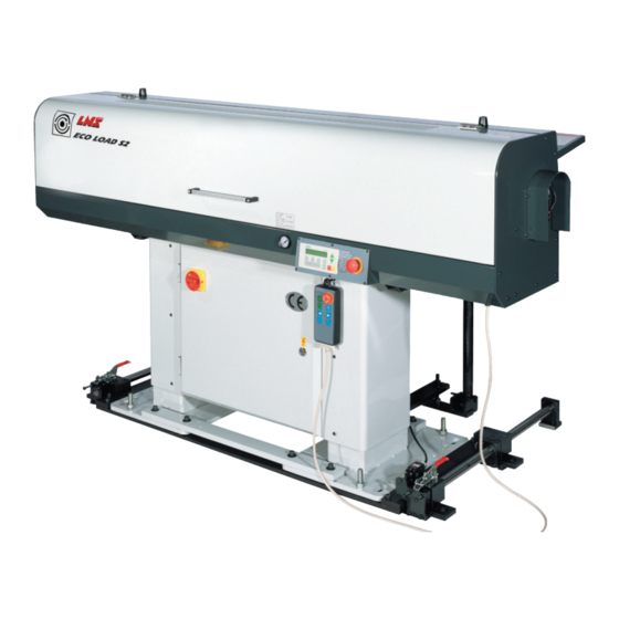
- Page 1 Instruction manual LNS SA 2534 Orvin/Switzerland www.LNS-group.com 9.ECO.01...
-
Page 3: Table Of Contents
V4.1 TABLE OF CONTENTS CHAPTER 1: BASIC NOTIONS ............... 1-1 STRUCTURE ......................... 1-2 RIGHTS ..........................1-3 DECLARATION OF COMPLIANCE ..................1-4 SAFETY INSTRUCTIONS ..................... 1-5 SAFETY DEVICES ........................ 1-6 ... - Page 4 CHAPTER 8: TROUBLESHOOTING GUIDE .......... 8-1 ALARMS ..........................8-2 CHAPTER 9: APPENDICES ..............9-1 ORDERING FORM ........................ 9-2 PROGRAMMING EXAMPLE ....................9-3 LNS ADDRESSES & CONTACTS ..................9-4 ECOLOAD S2...
-
Page 5: Chapter 1: Basic Notions
CHAPTER 1: BASIC NOTIONS CHAPTER 1: BASIC NOTIONS ECOLOAD S2... -
Page 6: Structure
(see chapter *) or (see point *). 1.2. Captions Whenever possible, the reference numbers contained in the instruction manual are shown with the LNS ordering number of the indicated element. To make it easier to place an order of supplies, a form has been included in the annex at the end of this manual. -
Page 7: Rights
LNS SA. LNS SA and its subsidiaries cannot be held responsible for damage and problems arising from the use of options and products other than LNS products, or products approved by LNS SA. -
Page 8: Declaration Of Compliance
We declare that the following machinery complies with the next directives : - Machinery Directive: 2006/42/EC - Low Voltage Directive: 2006/95/EC - EMC Directive : 2004/108/EC Manufacturer : LNS SA Route de Frinvillier CH- 2534 Orvin Suisse Compiling relevant technical information :... -
Page 9: Safety Instructions
All persons who perform work on this machine, must have read and understood the notice instructions. LNS disclaim all responsibility for possible accidents or property damage caused when safety instructions are not followed : ... -
Page 10: Safety Devices
By pressing the emergency stop button located on the remote control, the functions of the bar feed system and the lathe are immediately stopped. The LNS company, or its local representative, may not be held responsible for possible accidents or property damage, whether caused directly or not, by any means whatsoever, if certain safety devices have not been included. - Page 11 CHAPTER 1: BASIC NOTIONS 6.1. Layout of the safety elements on the bar feeder SQ10 SQ12 SQ12 Designation Description Emergency stop button on remote control Emergency stop button on electrical cabinet Main access cover Magazine cover SQ10 Safety switch of the main access cover SQ11 Safety switch of the magazine cover SQ12...
- Page 12 CHAPTER 1: BASIC NOTIONS ECOLOAD S2...
-
Page 13: Chapter 2: Technical Data
CHAPTER 2: TECHNICAL DATA CHAPTER 2: TECHNICAL DATA ECOLOAD S2... -
Page 14: Characteristics
CHAPTER 2: TECHNICAL DATA CHARACTERISTICS Note : Depending on the country and the standards in effect, certain technical data, such as the power supply, may vary. Please see the technical card delivered with the device. Ecoload S2 Bar diameter ¼” – 2-5/8” (5mm – 65mm) 12”... - Page 15 CHAPTER 2: TECHNICAL DATA 2.1. Without retraction system ECOLOAD S2...
- Page 16 CHAPTER 2: TECHNICAL DATA 2.2. X-axis retraction system ECOLOAD S2...
- Page 17 CHAPTER 2: TECHNICAL DATA 2.3. Z-axis retraction system ECOLOAD S2...
-
Page 18: Layout Of The Elements
CHAPTER 2: TECHNICAL DATA LAYOUT OF THE ELEMENTS Designation Description Main access cover Remote control Electrical cabinet Pusher Pusher carrier Loading channel Protection grate Magazine Magazine inclination adjustment Retraction system (optional) Front stand Rear stand ECOLOAD S2... -
Page 19: Chapter 3: Setting Into Operation
CHAPTER 3: SETTING INTO OPERATION CHAPTER 3: SETTING INTO OPERATION ECOLOAD S2... -
Page 20: Transportation
CHAPTER 3: SETTING INTO OPERATION TRANSPORTATION Please read the safety precautions described at the beginning of this manual before handling the following devices. 1.1. Description Depending on its destination, the ECOLOAD S2 bar feed system may be delivered either on a pallet, or packed in a wooden crate. -
Page 21: Lifting
CHAPTER 3: SETTING INTO OPERATION LIFTING For installing the bar feeder, it’s advisable to contact us or one of our branches, agents. We cannot be held responsible for any malfunction resulting from an incorrect installation in which we did not take part in. 2.1. -
Page 22: Mounting Of The Retraction System (Optional)
CHAPTER 3: SETTING INTO OPERATION MOUNTING OF THE RETRACTION SYSTEM (optional) The magazine slides with the bar feeder when the retraction is used. Before mounting the system, make sure the floor surface is flat and smooth. The retraction system allows the bar feeder moving on certain distance so that there is some space behind the spindle for service. - Page 23 CHAPTER 3: SETTING INTO OPERATION 3.2. Mounting of the Z-axis retraction system The Z-axis retraction system allows the bar feeder moves among the longitudinal direction. This movement gives more space on the lateral direction. Sensor protection Sensor Please follow the steps below to install the retraction system. ...
-
Page 24: Positioning
CHAPTER 3: SETTING INTO OPERATION POSITIONING The bar feeder must be placed behind the lathe as closer as it could be. The maximum distance between the lathe and bar feeder should not exceed 100mm. In the other words, the bar stock length should not exceed spindle length. 4.1. -
Page 25: Leveling
CHAPTER 3: SETTING INTO OPERATION LEVELING Before preceding this step, make sure that the lathe is leveled. 5.1. For bar feeders without retraction system Put the level on position C and D of bar feeder stand by sequence as shown. ... - Page 26 CHAPTER 3: SETTING INTO OPERATION 5.2. For bar feeder with X-axis retraction system Put the level on position C and D of bar feeder stand by sequence as shown. Loose nuts A on the stand. Level the bar feeder by adjusting screws B and E on each stand. Turn B clockwise until it touch against the plate under the stands to lift the bar feeder or turn it counter- clockwise to drop.
- Page 27 CHAPTER 3: SETTING INTO OPERATION 5.3. For bar feeder with Y-axis retraction system Put the level on position C and D of bar feeder stand by sequence as shown. Loose nuts A on the stand. Level the bar feeder by adjusting screw B on each stand. Turn itclockwise until it touch against the plate under the stands to lift the bar feeder or turn it counter- clockwise to drop.
-
Page 28: Alignment
3-10 CHAPTER 3: SETTING INTO OPERATION ALIGNMENT Open both stand covers. Make sure that nut B tightly contact to the plate C Open the electrical cabinet. Loose nuts A on both sides (total 6 nuts). Adjust the bar feeder height by turning nuts B on each stand. Note that nut D must be always locked and should not be adjusted. - Page 29 CHAPTER 3: SETTING INTO OPERATION 3-11 6.1. Center adjustment Continuously adjust nuts B until the pusher is at central of the spindle on both front and rear sides. When the alignment is finished, lock all the nuts A. Spindle Spindle rear end Spindle front end...
-
Page 30: Mounting Of The Magazine
3-12 CHAPTER 3: SETTING INTO OPERATION MOUNTING OF THE MAGAZINE The magazine was delivered without assembling. The user has to assemble it on the bar feeder before installation. Please follow the procedures below to install the magazine according to your bar feeder type. Magazine feeders without retraction system... - Page 31 CHAPTER 3: SETTING INTO OPERATION 3-13 2. Mount the magazine body A, magazine middle rod B and lock them with the brackets. 3. Mount the magazine stands C as shown. 4. Loose nut D. Tilt the magazine by adjusting nut E. Lock nut D after the adjustment is finished.
- Page 32 3-14 CHAPTER 3: SETTING INTO OPERATION 7.2. Bar feeders with retraction system 1. Unlock the magazine brackets by loosing screws pointed. 2. Mount the magazine body and middle rod B and lock them with the brackets. 3. Mount the magazine basement C as shown. 4.
- Page 33 CHAPTER 3: SETTING INTO OPERATION 3-15 5. Adjust nut E so that the plates F are parallel with the bar feeder stand plates. 6. Adjust nut G so that the magazine basement wheels J are able to contact with the ground. Then lock nuts H.
-
Page 34: Anchoring
3-16 CHAPTER 3: SETTING INTO OPERATION ANCHORING After the bar feeder is positioned, leveled, aligned and the magazine is mounted. The bar feeder must be anchored. Figures below offer the anchoring location for each model. Please refer to corresponding instruction and anchor your bar feeder accordingly. 8.1. -
Page 35: Connection
CHAPTER 3: SETTING INTO OPERATION 3-17 CONNECTION Once the bar feeder has been aligned and anchored to the ground, the bar feeder must be connected to the interface of the lathe and compressed air need to be connected. For the electrical connection, please see Chapter 4, Electrics. ... - Page 36 3-18 CHAPTER 3: SETTING INTO OPERATION ECOLOAD S2...
-
Page 37: Chapter 4: Electrics
CHAPTER 4: ELECTRICS CHAPTER 4: ELECTRICS ECOLOAD S2... -
Page 38: Electrical Equipment
Please read the safety instructions provided at the beginning of this manual before handling the following devices. Particular attention should be given to the handling of electrical elements because of risks of electrocution. In case of possible electrical malfunctions, it is advisable to contact LNS or their local representative. 1.1. Description This chapter contains all of the elements regarding the electrical circuit of the bar feed system. -
Page 39: Electrical Cabinet
CHAPTER 4: ELECTRICS ELECTRICAL CABINET Designation Description Transformer Protective ground terminal Printed Circuit Board (PCB) Programmable Logic Controller (PLC) 24V DC power supply breaker ECOLOAD S2... -
Page 40: Power Supply
CHAPTER 4: ELECTRICS POWER SUPPLY The main power is supplied by the interface cable. Before connecting the interface cable to the lathe, make sure the transformer wiring meet the power supply. AC System DC System AC 110V +24 / M Lathe Transformer Bridge... - Page 41 CHAPTER 4: ELECTRICS 3.2. QF2 breaker Breaker QF2 protects the one phase 220V AC which powers PLC. If the one phase required power exceeds 4A, the breaker activates and terminates 2 phases. After the problem is fixed, reset the breaker by flipping lever B up. Designation Description Power poles input...
-
Page 42: Diagrams
CHAPTER 4: ELECTRICS DIAGRAMS 4.1. Symbols Index Symbol Description Designation Pressure switch Capacity Main disconnect switch Bridge rectifier Fuse LED0, LED13 Light-emitting diode Circuit breaker R1 ~ R5 Relay S1~S7 Buttons SR1, SR2, SR3 Proximity switch STP1 / STP2 Emergency stop button Pressure switch ECOLOAD S2... - Page 43 CHAPTER 4: ELECTRICS 4.2. Circuit diagram ECOLOAD S2...
-
Page 44: Plc (Programmable Logic Controller)
CHAPTER 4: ELECTRICS PLC (Programmable logic controller) 5.1. Primary module The PLC processes the signals from the interface, sensors and remote control and sets the outputs according to the program logic. In addition, the PLC powers HMI with 24V DC. Designation Description Input contacts. - Page 45 CHAPTER 4: ELECTRICS 5.2. PLC I/O DIAGRAMS ECOLOAD S2...
- Page 46 4-10 CHAPTER 4: ELECTRICS 5.3. Input signals Contact Indicator Description Contact to Remarks 1 phases 110V input Q2 breaker Protective earth Lathe 1 phases 0V input Q2 breaker Common ground Power supply Phase A Encoder Encoder signals Phase B Encoder Origin reference SR3(TB23) Sensor...
- Page 47 CHAPTER 4: ELECTRICS 4-11 5.4. Output signals Contact Indicator Description Connect to Comment Independent DC power 24V DC power output supply for HMI. COM0 24V DC input for terminal Y00 empty COM1 24V DC input for terminal Y01 empty COM2 24V DC input for terminals Y02, Y03 Bar feeder is in auto mode Remote control LED attributed to button...
-
Page 48: Pcb (Printed Circuit Board)
4-12 CHAPTER 4: ELECTRICS PCB (Printed Circuit Board) PCB is a board with circuit printed and electrical components welded on the surface. It offers sockets and terminals for electrical components like relays, cables and fuses. Refer to the table below for functions of each terminal. -
Page 49: Interface
7.1. Description The interface cable(s), between the bar feed system and the lathe is (are) provided by LNS. Interface presents all the signals exchanged between the bar feeder and the lathe. The male interface cable(s) which serves to transmit the interface signals is/are provided by bar feeder. - Page 50 4-14 CHAPTER 4: ELECTRICS ECOLOAD S2...
- Page 51 CHAPTER 4: ELECTRICS 4-15 7.3. Signals from the bar feeder to the lathe When a specific bar feeder signal is activated, the corresponding relay energizes therefore send signal to the lathe. The bar feeder interface offers wires of both NO and NC contacts. The user should connect the interface wires according to lathe signal logic.
- Page 52 4-16 CHAPTER 4: ELECTRICS 7.4. Signals from the lathe to the bar feeder The lathe interface signal logic can be configured with service parameters. Only trained personnel should change these settings. a) 24V DC power supply All the signals from the lathe were powered by the 24V DC from the bar feeder. When the corresponding relay energized at the lathe, the 24V DC travels through corresponding contact and return to PLC.
-
Page 53: Safety Switches
CHAPTER 4: ELECTRICS 4-17 SAFETY SWITCHES Switch SQ11 Switch SQ10, SQ12 Swing arm Switch key 8.1. Main access cover safety sensor (SQ10) This sensor should be mounted on the bar feeder body and the latch mounted on the movable cover. When the main access cover is closed with the switch key plugged, wire 17 and 16 will be engaged but wire 116 and +24 will be disengaged so will not send signal to PLC input contact X16. - Page 54 4-18 CHAPTER 4: ELECTRICS ECOLOAD S2...
-
Page 55: Chapter 5: Pneumatics
CHAPTER 5: PNEUMATICS CHAPTER 5: PNEUMATICS ECOLOAD S2... -
Page 56: Pneumatical Equipment
CHAPTER 5: PNEUMATICS PNEUMATICAL EQUIPMENT Please read the safety instructions provided at the beginning of this manual before handling the following devices. 1.1. Description This bar feeder is mainly driven by pneumatic elements. To guarantee an optimal operation of the bar feed system, a minimum pressure of 5 bars (75 psi), and a maximum pressure of 6 bars (90 psi) is mandatory. -
Page 57: Pneumatic Circuit Diagram
CHAPTER 5: PNEUMATICS PNEUMATIC CIRCUIT DIAGRAM ECOLOAD S2... -
Page 58: Combination Unit (Filtering-Regulation-Lubrication)
CHAPTER 5: PNEUMATICS F.R.L. COMBINATION UNIT (Filtering-Regulation-Lubrication) 3.1. Description The F.R.L. (Filtering-Regulation-Lubrication) combination unit serves to perform filtering, lubrication and regulation of the pressure before it is distributed into the pneumatic circuit of the bar feed system. The air must be furnished at a maximum pressure of 6 bar (90 psi), and whenever possible, clean and dry. 3.2. -
Page 59: Solenoid Valve Manifold
CHAPTER 5: PNEUMATICS SOLENOID VALVE MANIFOLD 4.1. Description The solenoid valve manifold serves to control the cylinders. 4.2. Layout of the elements VAL3 VAL4 Designation Description 8mm (1/3 “) air inlet (from F.R.L. combination) VAL1 Air outlet with silencer VAL1 Move the pusher backward VAL2 Move the pusher forward... -
Page 60: Rodless Cylinder Formation And Maintenance
CHAPTER 5: PNEUMATICS RODLESS CYLINDER FORMATION AND MAINTENANCE Induction side Exhaust side Sliding plate Cylinder jar Oil Filler Point The cylinder is assembled by the cylinder jar, the piston in it and also the sliding plate. The piston and the sliding plate are connected due to magnetism. The cylinder jar is a hollow tube with piston which apart from exhaust and induction side. -
Page 61: Maintenance
CHAPTER 5: PNEUMATICS MAINTENANCE The pneumatic system should be regularly maintained in order to ensure the system is powered by qualified compressed air. We recommend the user to check the F.R.L. combination as instructed below every week. 6.1. Check the condensate collector The condensate collector is a measure of quality of the compressed air. - Page 62 CHAPTER 5: PNEUMATICS ECOLOAD S2...
-
Page 63: Chapter 6: General Description
CHAPTER 6: GENERAL DESCRIPTION CHAPTER 6: GENERAL DESCRIPTION ECOLOAD S2... -
Page 64: Loading System
CHAPTER 6: GENERAL DESCRIPTION LOADING SYSTEM Please read the safety precautions described at the beginning of this manual before handling the following devices. The loading system consists of bar magazine, loading fingers, stopping fingers and the loading cylinders. This system serves to storage and load bar stocks into the guiding channel. In order to load the bar stocks smoothly during automatic mode, the elements must be properly adjusted according to the bar stock profile and dimension. - Page 65 CHAPTER 6: GENERAL DESCRIPTION 1.2. Adjustment of the loading system 1.2.1. Stopping fingers The stopping fingers should be adjusted according to bar diameter so that only one bar stock will be loaded per loading cycle. Stopping finger 1.2.2. Magazine height As a generally rule, the magazine could be adjusted as the angle shown.
-
Page 66: Feeding System
CHAPTER 6: GENERAL DESCRIPTION FEEDING SYSTEM The feeding system consists of the pusher assembly, rodless transmission device and TOP CUT measuring device. With this system, the rodless cylinder drives the pusher forward and backward hence accomplish bar stock feeding. Designation Description Rodless cylinder Pusher carrier... -
Page 67: Transmission
CHAPTER 6: GENERAL DESCRIPTION TRANSMISSION Please read the safety precautions described at the beginning of this manual before handling the following devices. Transmission unit consists of rodless cylinder and encoder. The pusher carrier is driven by the pneumatic rodless cylinder. Without mechanical connection between the pusher and bar stock, it should keep some distance between pusher and rotating bar stock. -
Page 68: Pusher
CHAPTER 6: GENERAL DESCRIPTION PUSHER Please read the safety precautions described at the beginning of this manual before handling the following devices. 4.1. Description The pusher assembly is composed of short and long pusher. Item Function Note Short pusher First feed The movement inside bar feeder TOP CUT Long pusher... - Page 69 CHAPTER 6: GENERAL DESCRIPTION 4.2. Pusher replacement 1. Move the channel to 15° position ( 2. Move the pusher to middle of the channel ( 3. Remove the lock nut and PE bushing set screw. Be careful with the spring compressed behind the pusher rod. Hold the pusher rod tight before removing the set screw for fixing the pusher on the cylinder.
- Page 70 CHAPTER 6: GENERAL DESCRIPTION 6. Mount the PE bushing. Insert the front end of pusher rod into the PE bushing. Ensure the spring is inside the adapter. Insert the rear end of the pusher rod into the adapter 7. Lock the set screw for fixing the pusher rod. Ensure that the top surface of the set screw is lower than the adapter’s.
- Page 71 CHAPTER 6: GENERAL DESCRIPTION 4.3. Pushing force adjustment The pushing force could be changed by adjusting the air regulator according to the bar stock diameter. Since the pushing force is reduced by various bar stock boundary conditions includes material density, surface condition, rodless cylinder performance...
-
Page 72: Channel Set
6-10 CHAPTER 6: GENERAL DESCRIPTION CHANNEL SET 5.1. Description The channel set serves to support the bar stock during loading and FIRST FEED. The channel has 2 operating positions. Only specific operation could be operated at each position. 5.2. 15° position This position serves to push the bar stock forward outside the bar feeder (i.e. - Page 73 CHAPTER 6: GENERAL DESCRIPTION 6-11 5.3. 0° position This position serves to feed a new bar stock out of the bar feeder (i.e. feed it into the lathe spindle) by moving short pusher forward. By pressing button on the remote control when pusher is at home position, actions below take place by sequence: The loading fingers swing up and load a bar stock into the channel.
- Page 74 6-12 CHAPTER 6: GENERAL DESCRIPTION 5.4. Height adjustment The channel upper position must be adjusted according to bar stock diameter therefore the bar stock is positioned at the bar feeder feeding center when the channel is at 0° position. Follow the procedures below to adjust the channel upper position: Loose 2 locking handles as shown.
-
Page 75: Spindle Liner
CHAPTER 6: GENERAL DESCRIPTION 6-13 SPINDLE LINER The spindle liner acts as an extension of guiding system. It fills the gap between the bar stock and spindle inner surface hence constrict the space of vibration. The spindle liner serves to support the pusher and bar stock inside the spindle when the spindle inner diameter is larger than pusher’s. - Page 76 6-14 CHAPTER 6: GENERAL DESCRIPTION 6.3. Model B The one which seals the rear end of the spindle. There are 3 different designs available of the last piece. Select the mode which fit the lathe spindle or consult us for technical support. Model B.1 Model B.2 Model B.3...
-
Page 77: Chapter 7: Operation
CHAPTER 7: OPERATION CHAPTER 7: OPERATION ECOLOAD S2... -
Page 78: Remote Control
CHAPTER 7: OPERATION REMOTE CONTROL Please read the safety instructions provided at the beginning of this manual before handling the following devices. The remote control offers interface signal indicating LEDs and buttons for operating the bar feed system when it’s in MANUAL mode. Emergency Stop Button Signal Display Area Function Keys... - Page 79 CHAPTER 7: OPERATION 1.2. Functions keys Emergency stop When a dangerous situation arises, pressing the emergency stop button immediately interrupts the bar feeder. The bar feeder will send alarm signal to the lathe and interrupt the lathe if interface is wired accordingly. Error message e01 will be shown on the HMI display.
-
Page 80: Hmi (Human Machine Interface)
CHAPTER 7: OPERATION HMI (Human Machine Interface) The HMI allows the user to read messages and set parameters Status indicating area Current pusher position Text display area Numerical Key Pad Command Keys 2.1. Text display area The display provides parameters, status information and error messages: After powering up, the screen shown left is displayed. - Page 81 CHAPTER 7: OPERATION 2.3. Command keys Increase / decrease the numerical value of a specific digit. Example : If one digit is “4”, increase it to “5” by pressing or decrease it to “3” by pressing Move the blinking cursor to the left / right. Example : If the cursor is current staying at ”4”...
-
Page 82: Powering And Emergency Stop
CHAPTER 7: OPERATION POWERING AND EMERGENCY STOP 3.1. Powering up The pusher carrier of bar feeder is equipped with an absolute encoder that continuously reads the position of the pusher. When the bar feeder is powered down or there is a power failure, this position is kept in the memory by the PLC. - Page 83 CHAPTER 7: OPERATION 3.2. Emergency stop buttons When a dangerous situation arises, press one of the emergency stop buttons. Actions below will be initiated and interrupts the bar feeder and the lathe (if interface wired accordingly): PLC output contact Y04 is ON. Alarm e01 is shown on HMI.
-
Page 84: Automatic / Manual Sequence
CHAPTER 7: OPERATION AUTOMATIC / MANUAL SEQUENCE 4.1. Turn the frame to 15° in manual mode Conditions below must be fulfilled: 1. The lathe is not in AUTOMATIC mode. 2. The V Channel is at 0° position (SR1 ON). 3. No material inside lathe spindle. Steps to move the frame to 15°: 1. - Page 85 CHAPTER 7: OPERATION 4.4. Start a new machining Conditions must be fulfilled before proceeding automatic sequence: 1. The lathe is not in AUTOMATIC mode. 2. The lathe chuck is open. 3. The lathe stopper must be positioned at the TOP CUT position. 4.
- Page 86 7-10 CHAPTER 7: OPERATION 4.5. Bar feeder in automatic mode Steps continue 4.4: 4.5.1. Automatic cycle - Production 11. Check END OF BAR signal. - If it’s activated, proceed step 20. - If it’s not activated, proceed the next step. 12.
-
Page 87: Operation Parameters
CHAPTER 7: OPERATION 7-11 OPERATION PARAMETERS The operation parameters are most frequently changed parameters for controlling the bar feeder when it’s in AUTOMATIC mode. All the operation parameters could be changed according to the machining requirement. To achieve the best performance, the operator is strongly recommended to read this chapter before proceeding any modification. - Page 88 7-12 CHAPTER 7: OPERATION 5.2. Description Only parameters inside rectangular are adjustable. Unit for all the length / position related parameters is mm. The bar stock positioning control logic The ECOLOAD S2 pusher was designed to be stopped with auxiliary of the stopper inside the lathe.
- Page 89 CHAPTER 7: OPERATION 7-13 This parameter should be MODIFIED if P03 Feeding length production part changed. The distance of bar stock needed to be fed for making a part. Position Current pusher position (measured from home position). Part Length The needed feeding part length is : <...
- Page 90 7-14 CHAPTER 7: OPERATION TOP CUT TOP CUT is the process which cuts few millimeters off from a new bar stock tip for creating a precise positioning reference of the next feeding. It presents the distance where the end face of a bar stock needs to travel from the bar feeder for proceeding TOP CUT machining.
- Page 91 CHAPTER 7: OPERATION 7-15 P08 FIRST FEED Position Current short pusher position measured from home position SR3. 1’st feed limit The distance where the short pusher needs to travel for moving the bar stock completely out of the channel. This parameter must be set to 1594 and should never be changed.
-
Page 92: Service Parameters
Service parameters must only be modified by technicians of or personnel authorized by LNS. Incorrect setup might cause unexpected malfunction or damage on either bar feeder or lathe. Accessing these parameters is password protected. Please contact LNS or its official agent in your country for getting technical support in case any modification is needed. - Page 93 CHAPTER 7: OPERATION 7-17 6.2. Description MODE 1 Simulation When this MODE is ON, the bar feeder runs feeding and bar change cycles automatically and not controlled by either interface signals or manual operation. This MODE is for factory test or exhibition purpose only. When it’s connected with the lathe, it must always be turned OFF.
- Page 94 7-18 CHAPTER 7: OPERATION MODE 6 This parameter intentionally left blank. MODE 7 M-function (A3) logic setup 2 of 2 Define if the bar feeder needs M-function or not. 0 – Bar feeder feeds the bar stock according to chuck signal only.
- Page 95 CHAPTER 7: OPERATION 7-19 Bar change Machining Stopper Last feeding Bar change Chuck signal Top cut Mode 10 = 0 Top cut Mode 10 =1 Eject Bar end remnant Eject remnant MODE 11 / 12 / 13 /22 BAR END signal setup Refer to the figure below.
- Page 96 7-20 CHAPTER 7: OPERATION MODE 14 START signal setup Define when START signal is sent during remnant ejection. 0 – Start signal is sent after pusher is pushed to P07 position. 1 – Start signal is sent if pusher touches any obstacle during remnant ejection.
- Page 97 CHAPTER 7: OPERATION 7-21 MODE 18 Length check skip Define the number of feeding length check skipped after a new bar stock was loaded at TOP CUT position. This number is available from 1 to 5. MODE 19 Length unit setup Define the unit used of those parameters related to length on HMI.
- Page 98 7-22 CHAPTER 7: OPERATION ECOLOAD S2...
-
Page 99: Chapter 8: Troubleshooting Guide
CHAPTER 8: TROUBLESHOOTING GUIDE CHAPTER 8: TROUBLESHOOTING GUIDE ECOLOAD S2... -
Page 100: Alarms
Particular attention should be given to the handling of electrical elements because of risks of electrocution. In case of possible electrical malfunctions, it is advisable to contact LNS or their local representative. This chapter lists all the error messages description and brief troubleshooting. The error messages aim to remind the operator that an abnormal situation probably exists. - Page 101 CHAPTER 8: TROUBLESHOOTING GUIDE 1.2. Error message map The table offers the sequence while both bar feeder and lathe are running under AUTOMATIC mode and the timing of related alarms are activated. Please note the table simplified AUTOMATIC sequence and only presented general selected necessary steps.
- Page 102 CHAPTER 8: TROUBLESHOOTING GUIDE 1.3. Error message description and troubleshooting guide An error code means signals combination from sensors which match error code definition in the PLC program. Follow the troubleshooting procedures below to solve the problems and reset the bar feeder from the error by pressing the MANUAL mode key.
- Page 103 CHAPTER 8: TROUBLESHOOTING GUIDE This parameter intentionally left blank. This parameter intentionally left blank. e06 Top cut setup is too long Description Positions BAR END, EJECTION and FIRST FEED have been passing through but TOP CUT position is not arrived. Troubleshooting Check if TOP CUT setup is too long.
- Page 104 CHAPTER 8: TROUBLESHOOTING GUIDE e09 FIRST FEED process could not be initiated 1 of 2 Description For bar feeders that MODE 7 = 1. When the bar feeder is ready for proceeding FIRST FEED, M-code is not activated within 15 seconds. Troubleshooting Check if M-code signal is wired in the interface cable.
- Page 105 CHAPTER 8: TROUBLESHOOTING GUIDE e13 Feeding length is too short Description When lathe chuck is open, the pusher feeding length is smaller than parameter P01 <Too short dist> setup. Troubleshooting Check if the lathe stopper is correctly positioned. Check if parameter P01<Too short dist> correctly set up. Check if the lathe chuck is too tight.
- Page 106 CHAPTER 8: TROUBLESHOOTING GUIDE e17 FIRST FEED positioning is failed Description The bar feeder fails to position the bar stock at FIRST FEED position according to P08 setting within 10 seconds. Troubleshooting Check if the channel or lathe spindle is blocked. Check if the pushing force is too small to push the bar stock.
- Page 107 CHAPTER 8: TROUBLESHOOTING GUIDE e21 Pusher moving distance is too long when chuck is closed Description The pusher moving distance is larger than <Too long dist> setup in P01 when the lathe chuck is closed. Troubleshooting Check if the chuck signal received but the lathe chuck is still closed.
- Page 108 8-10 CHAPTER 8: TROUBLESHOOTING GUIDE e26 Check TOP CUT setup Description New bar pushed to the lathe, if the pushing forward distance is greater than “Top-cut + part length + 50mm”, it will show this alarm. Troubleshooting Check if the TOP CUT setup is too small. Check if the lathe stopper position is incorrect.
-
Page 109: Chapter 9: Appendices
CHAPTER 9: APPENDICES CHAPTER 9: APPENDICES ECOLOAD S2... -
Page 110: Ordering Form
CHAPTER 9: APPENDICES ORDERING FORM This form should be photocopied, duly filled out, and returned to your retailer or nearest LNS agent Company name: Person in charge: Address: ZIP: City: Country: Phone: Fax: Type of device: Serial number: Qty. Ordering no. -
Page 111: Programming Example
CHAPTER 9: APPENDICES PROGRAMMING EXAMPLE MAIN PROGRAM N... ”M” CODE “LATHE IN AUTOMATIC CYCLE” N... SPINDLE STOP N... COOLANT OFF N... TURRET TO FEED IN POSITION N... COLLET OPEN N... TURRET TO FEED OUT POSITION N... END OF BAR CHECK >... -
Page 112: Lns Addresses & Contacts
CHAPTER 9: APPENDICES LNS ADDRESSES & CONTACTS LNS Europe : www.lns-europe.com LNS America : www.lns-america.com LNS Asia : www.lns-asia.com ECOLOAD S2...
Need help?
Do you have a question about the Eco Load S2 and is the answer not in the manual?
Questions and answers