Sign In
Upload
Download
Table of Contents
Contents
Add to my manuals
Delete from my manuals
Share
URL of this page:
HTML Link:
Bookmark this page
Add
Manual will be automatically added to "My Manuals"
Print this page
×
Bookmark added
×
Added to my manuals
Manuals
Brands
LNS Manuals
Industrial Equipment
Sprint 545 S2
Instruction manual
LNS Sprint 545 S2 Instruction Manual
Hide thumbs
1
2
Table Of Contents
3
4
5
6
7
8
9
10
11
12
13
14
15
16
17
18
19
20
21
22
23
24
25
26
27
28
29
30
31
32
33
34
35
36
37
38
39
40
41
42
43
44
45
46
47
48
49
50
51
52
53
54
55
56
57
58
59
60
61
62
63
64
65
66
67
68
69
70
71
72
73
74
75
76
77
78
79
80
81
82
83
84
85
86
87
88
89
90
91
92
93
94
95
96
97
98
99
100
101
102
103
104
105
106
107
108
109
110
111
112
113
114
page
of
114
Go
/
114
Contents
Table of Contents
Bookmarks
Table of Contents
Table of Contents
Chapter 1 : Basic Principles
Structure
Rights
Safety Requirements
Safety Devices
Chapter 2 : Technical Data
Characteristics
Floor Plan
Layout of the Elements
Chapter 3 : System Start up
Transportation
Assembly
Anchoring
Connections
Chapter 4 : Electrics
Electrical Equipment
Electrical Cabinet
Interface Diagram
Interface
Chapter 5 : Pneumatics
Pneumatic Equipment
Air Handling
Pneumatic Battery
Chapter 6 : Hydraulics
Hydraulic Equipment
Hydraulic Elements
Chapter 7 : General Description
Bar Magazine
Guiding Blocks
Pusher
Belt Drive
REMNANT EXTRACTION SYSTEM (Option)
Front Rest
RETRACTION DEVICE (Option)
Position Option
AUTOMATIC FRONT REST (Option)
POSITION PNEUMATIC FRONT REST (Option)
Chapter 8 : Handling
Powering on
Remote Control
Set-Up
Software Settings
Parts Library
Service
Help Screens
Automatic Cycle
End of Bar Position
Top-Cut Position
Powering down
Chapter 9 : Malfunctions
Factors Affecting Performance
Maintenance
Chapter 10 : Appendices
Programming Example
Ordering Form
Lns Addresses
Advertisement
Quick Links
Download this manual
Instruction Manual
ENG
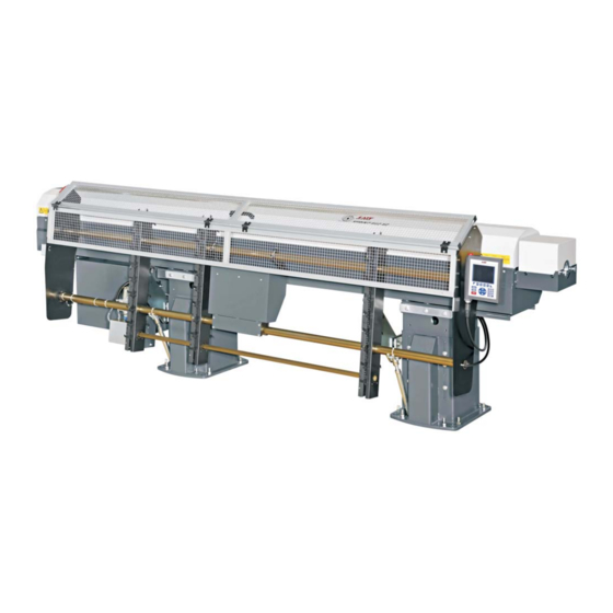
Sprint 545 / 565 S2
®
LNS SA
CH-2534 Orvin
www.LNS-group.com
9.545.01.ANG
Table of
Contents
Previous
Page
Next
Page
1
2
3
4
5
Advertisement
Table of Contents
Need help?
Do you have a question about the Sprint 545 S2 and is the answer not in the manual?
Ask a question
Questions and answers
Related Manuals for LNS Sprint 545 S2
Industrial Equipment LNS HYDROBAR SPRINT 542 Instruction Manual
(126 pages)
Industrial Equipment LNS Sprint 565 S2 Instruction Manual
(114 pages)
Industrial Equipment LNS Hydrobar SPRINT 555 Instruction Manual
Automatic magazine bar loader (136 pages)
Industrial Equipment LNS HYDROBAR SPRINT S3 Instruction Manual
(102 pages)
Industrial Equipment LNS HYDROBAR SPRINT S3 Instruction Manual
(79 pages)
Industrial Equipment LNS QUICK SIX Troubleshooting Manual
(124 pages)
Industrial Equipment LNS Alpha 552 Instruction Manual
Bar feeder (118 pages)
Industrial Equipment LNS Hydrobar Express 332 Troubleshooting And Spare Parts Manual
(186 pages)
Industrial Equipment LNS Quick Load Servo 65 Troubleshooting Manual
(129 pages)
Industrial Equipment LNS ALPHA 538 Instruction Manual
Barfeed (115 pages)
Industrial Equipment LNS Hydrobar Express 220 Startup Manual
(17 pages)
Industrial Equipment LNS QUICK LOAD SERVO 80 S2 BARFEED Instruction Manual
(111 pages)
Industrial Equipment LNS QUICK LOAD SERVO S3 T BARFEED Service Manual
(152 pages)
Industrial Equipment LNS QL Servo 80 S2 Service Manual
(143 pages)
Industrial Equipment LNS Hydrobar Express 220 Troubleshooting And Spare Parts Manual
(164 pages)
Industrial Equipment LNS QUICK LOAD SERVO III MI Instruction Manual
(130 pages)
This manual is also suitable for:
Sprint 565 s2
Table of Contents
Save PDF
Print
Rename the bookmark
Delete bookmark?
Delete from my manuals?
Login
Sign In
OR
Sign in with Facebook
Sign in with Google
Upload manual
Upload from disk
Upload from URL


Need help?
Do you have a question about the Sprint 545 S2 and is the answer not in the manual?
Questions and answers