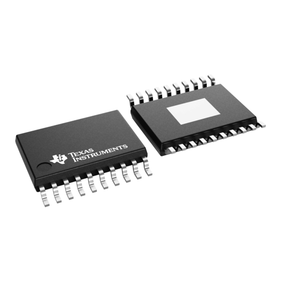
Summary of Contents for Texas Instruments TPS60120EVM-174
- Page 1 TPS60120EVM 174 Battery Powered, Dual Output Power Supply EVM For DSP's User’s Guide September 2000 Power Management Products SLVU035...
- Page 2 IMPORTANT NOTICE Texas Instruments and its subsidiaries (TI) reserve the right to make changes to their products or to discontinue any product or service without notice, and advise customers to obtain the latest version of relevant information to verify, before placing orders, that information being relied on is current and complete. All products are sold subject to the terms and conditions of sale supplied at the time of order acknowledgment, including those pertaining to warranty, patent infringement, and limitation of liability.
- Page 3 Preface About This Manual This user’s guide describes the TPS60120EVM-174 battery-powered, dual- output evaluation module (SLVP174). The SLVP174 provides a convenient method for evaluating the performance of a dual-output linear regulator. How to Use This Manual Chapter 1 – Introduction Chapter 2 –...
- Page 4 Trademarks Related Documentation From Texas Instruments TPS70751 data sheet (literature number SLVS291) TPS60120 data sheet (literature number SLVS257B) TPS60120EVM-142 user’s guide (literature number SLVU022) Trademarks PowerPAD is a trademark of Texas Instruments.
-
Page 5: Table Of Contents
Running Title—Attribute Reference Contents Introduction ..............1–1 Low Power DC/DC Converter . - Page 6 1–1 TPS60120EVM-174 Bill of Materials ..........
-
Page 7: Introduction
Chapter 1 Introduction This user’s guide describes the TPS60120EVM-174 battery-powered, dual-output power supply evaluation module (SLVP174). This power supply solution is comprised of a TPS60120 low-power dc/dc converter and a TPS70751 dual LDO regulator with integrated supervisory and power-up sequencing circuitry. Figure 1-1 shows a block diagram of the EVM. The DSP is not part of the EVM. -
Page 8: Low Power Dc/Dc Converter
0.055-µA current in shutdown mode Low-battery indicator Available in thermally enhanced TSSOP package (PowerPAD ) For a complete functional description, refer to the TPS60120 data sheet, SLVS257, and the Charge Pump application note, SLVA070. PowerPAD is a trademark of Texas Instruments. Introduction... -
Page 9: Ldo Regulator
LDO Regulator 1.2 LDO Regulator LDO regulators use a series pass element, feedback network, including an error amplifier and voltage reference to provide a regulated output voltage from a slightly larger and variable input voltage. Specific features of the TPS707xx family of dual LDO regulators include: Fixed and adjustable dual-output voltages optimized for low power DSPs and processor power supplies Logic selectable power-up sequencing... -
Page 10: Design Strategy
Design Strategy 1.3 Design Strategy The demand for smaller electronic devices is driving the need for innovative battery powered solutions including smaller batteries because smaller batteries provide smaller voltages. Since the battery supply voltages vary over the life of the battery, it is necessary to have a dc/dc converter capable of providing a regulated output over a wide range of input voltages. -
Page 11: Adjustment By Switch And Jumper
Adjustment by Switch and Jumpers As with any power solution, the output voltages should be monitored to ensure that the electronics are properly notified and shut down if the voltages fall below a predetermined threshold. The TPS70751 monitors both 3.3-V and 1.8-V outputs and provides an open drain, active low, 120-ms delayed RESET output. -
Page 12: Schematic
Schematic 1.5 Schematic Figure1–2 shows the TPS60120EVM-174 schematic diagram. Figure 1–2. Schematic Diagram TPS60120EVM-174 Introduction... -
Page 13: Bill Of Materials
Bill of Materials 1.6 Bill of Materials Table 1–2 lists materials required for the TPS60120EVM-174. Table 1–1. TPS60120EVM-174 Bill of Materials Ref Des Qty Part Number Description Size BH2AA–PC Battery holder, 2 AA cells, PC mount Capacitor, ceramic, 0.1 µF, 16 V, X7R... -
Page 14: Board Layout
Board Layout 1.7 Board Layout Figures 1–3 and 1-4 show the board layout for the TPS60120EVM-174. Figure 1–3. Top Layer Figure 1–4. Bottom Layer (top view) Introduction... - Page 15 Board Layout Figure 1–5. Assembly Introduction...
-
Page 16: Evm Test Setup
Chapter 2 EVM Test Setup This chapter provides a recommended test setup. Figure 2–1 shows the test setup. Follow these steps for initial power up of the SLVP174: 1) Adjust the settings of the jumpers to fit test requirements. If the battery pack is selected as the input, install two AA alkaline batteries into the battery pack on the back of the board. - Page 17 EVM Test Setup...
-
Page 18: Test Results
Chapter 3 Test Results This chapter presents laboratory test results for the TPS60120EVM-174. Topic Page Test Results .......... -
Page 19: Test Results
3.1 Test Results Figures 3–1 through 3–6 show the results of various test conditions using the TPS60120EVM-174. Figures 3–1 shows the startup curves of the 3.3-V output (CH1) and 1.8-V output (CH2) of the EVM. Each at no load using switch SW1 to manually trigger start up. -
Page 20: Start-Up Curves (Tps60120 And Tps70751)
Test Results Figures 3–3 shows the startup curves of the TPS60120, 3.3-V output( CH1), and the TPS70751, 3.3-V output (CH1) and 1.8-V output (CH2). Switch SW1 was disconnected and the TPS60120 ENABLE (CH3) pin was enabled using a pulse generator. Both TPS70751 outputs have 1 mA loads. The TPS60120 output is distorted due to the load on the charge pump from the charging of the TPS70751 output capacitors and the 1 mA loads. - Page 21 Test Results Figures 3–5 shows an ac measurement of the TPS60120, 3.3-V output, with each TPS70751 output loaded with 100 mA. Figure 3–5. AC Measurements (TPS60120) Figures 3–6 shows an ac measurement of the TPS70751, 3.3-V output (CH1) and 1.8-V output (CH2), each loaded with 100 mA. The TPS70751 3.3-V output capacitors provide some filtering of the TPS60120 3.3-V output waveform shown in Figure 3–5.
- Page 22 Mouser Electronics Authorized Distributor Click to View Pricing, Inventory, Delivery & Lifecycle Information: Texas Instruments TPS60120EVM-174...


Need help?
Do you have a question about the TPS60120EVM-174 and is the answer not in the manual?
Questions and answers