Table of Contents
Advertisement
Quick Links
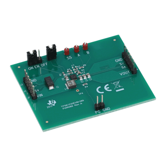
This user's guide describes the characteristics, operation, and use of TI's TPS61230 evaluation module
(EVM). This EVM is designed to help the user easily evaluate and test the operation and functionality of
the TPS61230. The EVM converts a 2.3-V to 5.5-V input voltage to a regulated 5-V output voltage. The
TPS61230 is capable of delivering 2.1-A current while the input voltage is above 3.3 V. This user's guide
includes setup instructions for the hardware, a printed-circuit board (PCB) layout for the EVM, a schematic
diagram, a bill of materials (BOM), and test results for the EVM.
...................................................................................................................
1
..........................................................................................................................
2
3
4
5
Schematic and Bill of Materials
1
Bode Plot for V
2
3
.....................................................................................................................
4
5
6
1
Performance Specification Summary
2
TPS61230EVM-089 Bill of Materials
1
Introduction
The TPS61230 is a 5-A switch current limit, synchronous, step-up converter in a 3 × 3-mm, 10-pin QFN
package. The output voltage is adjustable.
1.1
Background
The TPS61230EVM-089 is set to a 5-V output. The EVM operates with full-rated performance with an
input voltage between 3.3 V and 5.5 V. If Vin is below 3.3 V, the output current capability could be less
than 2.1 A.
SLVU761A - October 2013 - Revised March 2014
Submit Documentation Feedback
TPS61230EVM-089 Evaluation Module
.........................................................................................
.................................................................................................................
............................................................................................
= 3.3 V, V
= 5 V, I
= 2.1 A
IN
OUT
OUT
..............................................................................................................
................................................................................................................
.................................................................................................................
............................................................................................
.....................................................................................
......................................................................................
Copyright © 2013-2014, Texas Instruments Incorporated
SLVU761A - October 2013 - Revised March 2014
Contents
List of Figures
.......................................................................
List of Tables
TPS61230EVM-089 Evaluation Module
User's Guide
1
2
3
4
6
3
4
4
5
5
6
2
7
1
Advertisement
Table of Contents

Subscribe to Our Youtube Channel
Related Manuals for Texas Instruments TPS61230EVM-089


Summary of Contents for Texas Instruments TPS61230EVM-089
-
Page 1: Table Of Contents
The output voltage is adjustable. Background The TPS61230EVM-089 is set to a 5-V output. The EVM operates with full-rated performance with an input voltage between 3.3 V and 5.5 V. If Vin is below 3.3 V, the output current capability could be less than 2.1 A. -
Page 2: Introduction
Introduction www.ti.com Performance Specification Table 1 provides a summary of the TPS61230EVM-089 performance specifications. All specifications are given for an ambient temperature of 25°C. Table 1. Performance Specification Summary Specification Test Conditions Unit Input voltage Output voltage PWM mode PFM mode 5.035... -
Page 3: Tps61230Evm-089 Test Results
The TPS61230EVM-089 was used to take the data in the TPS61230 datasheet. See the device data sheet for the performance of this EVM. Loop Response Plot The loop response of the TPS61230EVM-089 can be measured by injecting the ac signal across R6. The loop response bode plot under typical condition is shown in Figure Figure 1. -
Page 4: Board Layout
Board Layout www.ti.com Board Layout Figure 2 through Figure 5 illustrate the TPS61230EVM-089 PCB layout. The gerbers are available on the EVM product page: TPS61230EVM-089. VOUT 2013 PG GND PG GND Figure 2. Assembly Layer VOUT 2013 PG GND PG GND Figure 3. -
Page 5: Top Layer
Board Layout www.ti.com Figure 4. Top Layer Figure 5. Bottom Layer SLVU761A – October 2013 – Revised March 2014 TPS61230EVM-089 Evaluation Module Submit Documentation Feedback Copyright © 2013–2014, Texas Instruments Incorporated... -
Page 6: Tps61230Evm-089 Schematic
Schematic and Bill of Materials www.ti.com Schematic and Bill of Materials This section provides the TPS61230EVM-089 schematic and BOM. Schematic Figure 6 illustrates the EVM schematic. Figure 6. TPS61230EVM-089 Schematic TPS61230EVM-089 Evaluation Module SLVU761A – October 2013 – Revised March 2014 Submit Documentation Feedback Copyright ©... - Page 7 TPS61230DRC Current Limit The TPS61230EVM-089 may be populated with TPS61230 (U1) devices that do not contain the correct top side markings on the top of the device itself. These devices are still fully-tested TPS61230 devices and meet the specified electrical characteristics of the data sheet.
- Page 8 NOTE: Page numbers for previous revisions may differ from page numbers in the current version. NOTE: Page numbers for previous revisions may differ from page numbers in the current version. Revision History SLVU761A – October 2013 – Revised March 2014 Submit Documentation Feedback Copyright © 2013–2014, Texas Instruments Incorporated...
- Page 9 ADDITIONAL TERMS AND CONDITIONS, WARNINGS, RESTRICTIONS, AND DISCLAIMERS FOR EVALUATION MODULES Texas Instruments Incorporated (TI) markets, sells, and loans all evaluation boards, kits, and/or modules (EVMs) pursuant to, and user expressly acknowledges, represents, and agrees, and takes sole responsibility and risk with respect to, the following: 1.
- Page 10 RADIO FREQUENCY REGULATORY COMPLIANCE INFORMATION FOR EVALUATION MODULES Texas Instruments Incorporated (TI) evaluation boards, kits, and/or modules (EVMs) and/or accompanying hardware that is marketed, sold, or loaned to users may or may not be subject to radio frequency regulations in specific countries.
- Page 11 Les types d'antenne non inclus dans cette liste, ou dont le gain est supérieur au gain maximal indiqué, sont strictement interdits pour l'exploitation de l'émetteur. Mailing Address: Texas Instruments, Post Office Box 655303, Dallas, Texas 75265 Copyright © 2014, Texas Instruments Incorporated spacer Important Notice for Users of EVMs Considered “Radio Frequency Products”...
- Page 12 IMPORTANT NOTICE Texas Instruments Incorporated and its subsidiaries (TI) reserve the right to make corrections, enhancements, improvements and other changes to its semiconductor products and services per JESD46, latest issue, and to discontinue any product or service per JESD48, latest issue.
Need help?
Do you have a question about the TPS61230EVM-089 and is the answer not in the manual?
Questions and answers